US11223060B2 - Electrochemical reaction single cell and electrochemical reaction cell stack - Google Patents
Electrochemical reaction single cell and electrochemical reaction cell stack Download PDFInfo
- Publication number
- US11223060B2 US11223060B2 US16/485,557 US201716485557A US11223060B2 US 11223060 B2 US11223060 B2 US 11223060B2 US 201716485557 A US201716485557 A US 201716485557A US 11223060 B2 US11223060 B2 US 11223060B2
- Authority
- US
- United States
- Prior art keywords
- integrated value
- single cell
- electrochemical reaction
- cathode
- electrolyte layer
- Prior art date
- Legal status (The legal status is an assumption and is not a legal conclusion. Google has not performed a legal analysis and makes no representation as to the accuracy of the status listed.)
- Active, expires
Links
Images


Classifications
-
- H—ELECTRICITY
- H01—ELECTRIC ELEMENTS
- H01M—PROCESSES OR MEANS, e.g. BATTERIES, FOR THE DIRECT CONVERSION OF CHEMICAL ENERGY INTO ELECTRICAL ENERGY
- H01M4/00—Electrodes
- H01M4/86—Inert electrodes with catalytic activity, e.g. for fuel cells
-
- C—CHEMISTRY; METALLURGY
- C25—ELECTROLYTIC OR ELECTROPHORETIC PROCESSES; APPARATUS THEREFOR
- C25B—ELECTROLYTIC OR ELECTROPHORETIC PROCESSES FOR THE PRODUCTION OF COMPOUNDS OR NON-METALS; APPARATUS THEREFOR
- C25B1/00—Electrolytic production of inorganic compounds or non-metals
- C25B1/01—Products
- C25B1/02—Hydrogen or oxygen
- C25B1/04—Hydrogen or oxygen by electrolysis of water
-
- C—CHEMISTRY; METALLURGY
- C25—ELECTROLYTIC OR ELECTROPHORETIC PROCESSES; APPARATUS THEREFOR
- C25B—ELECTROLYTIC OR ELECTROPHORETIC PROCESSES FOR THE PRODUCTION OF COMPOUNDS OR NON-METALS; APPARATUS THEREFOR
- C25B13/00—Diaphragms; Spacing elements
- C25B13/04—Diaphragms; Spacing elements characterised by the material
-
- C—CHEMISTRY; METALLURGY
- C25—ELECTROLYTIC OR ELECTROPHORETIC PROCESSES; APPARATUS THEREFOR
- C25B—ELECTROLYTIC OR ELECTROPHORETIC PROCESSES FOR THE PRODUCTION OF COMPOUNDS OR NON-METALS; APPARATUS THEREFOR
- C25B9/00—Cells or assemblies of cells; Constructional parts of cells; Assemblies of constructional parts, e.g. electrode-diaphragm assemblies; Process-related cell features
- C25B9/17—Cells comprising dimensionally-stable non-movable electrodes; Assemblies of constructional parts thereof
- C25B9/19—Cells comprising dimensionally-stable non-movable electrodes; Assemblies of constructional parts thereof with diaphragms
-
- C—CHEMISTRY; METALLURGY
- C25—ELECTROLYTIC OR ELECTROPHORETIC PROCESSES; APPARATUS THEREFOR
- C25B—ELECTROLYTIC OR ELECTROPHORETIC PROCESSES FOR THE PRODUCTION OF COMPOUNDS OR NON-METALS; APPARATUS THEREFOR
- C25B9/00—Cells or assemblies of cells; Constructional parts of cells; Assemblies of constructional parts, e.g. electrode-diaphragm assemblies; Process-related cell features
- C25B9/70—Assemblies comprising two or more cells
- C25B9/73—Assemblies comprising two or more cells of the filter-press type
- C25B9/77—Assemblies comprising two or more cells of the filter-press type having diaphragms
-
- H—ELECTRICITY
- H01—ELECTRIC ELEMENTS
- H01M—PROCESSES OR MEANS, e.g. BATTERIES, FOR THE DIRECT CONVERSION OF CHEMICAL ENERGY INTO ELECTRICAL ENERGY
- H01M8/00—Fuel cells; Manufacture thereof
- H01M8/10—Fuel cells with solid electrolytes
- H01M8/12—Fuel cells with solid electrolytes operating at high temperature, e.g. with stabilised ZrO2 electrolyte
- H01M8/1213—Fuel cells with solid electrolytes operating at high temperature, e.g. with stabilised ZrO2 electrolyte characterised by the electrode/electrolyte combination or the supporting material
-
- H—ELECTRICITY
- H01—ELECTRIC ELEMENTS
- H01M—PROCESSES OR MEANS, e.g. BATTERIES, FOR THE DIRECT CONVERSION OF CHEMICAL ENERGY INTO ELECTRICAL ENERGY
- H01M8/00—Fuel cells; Manufacture thereof
- H01M8/10—Fuel cells with solid electrolytes
- H01M8/12—Fuel cells with solid electrolytes operating at high temperature, e.g. with stabilised ZrO2 electrolyte
- H01M8/124—Fuel cells with solid electrolytes operating at high temperature, e.g. with stabilised ZrO2 electrolyte characterised by the process of manufacturing or by the material of the electrolyte
- H01M8/1246—Fuel cells with solid electrolytes operating at high temperature, e.g. with stabilised ZrO2 electrolyte characterised by the process of manufacturing or by the material of the electrolyte the electrolyte consisting of oxides
- H01M8/1253—Fuel cells with solid electrolytes operating at high temperature, e.g. with stabilised ZrO2 electrolyte characterised by the process of manufacturing or by the material of the electrolyte the electrolyte consisting of oxides the electrolyte containing zirconium oxide
-
- H—ELECTRICITY
- H01—ELECTRIC ELEMENTS
- H01M—PROCESSES OR MEANS, e.g. BATTERIES, FOR THE DIRECT CONVERSION OF CHEMICAL ENERGY INTO ELECTRICAL ENERGY
- H01M8/00—Fuel cells; Manufacture thereof
- H01M8/24—Grouping of fuel cells, e.g. stacking of fuel cells
-
- H—ELECTRICITY
- H01—ELECTRIC ELEMENTS
- H01M—PROCESSES OR MEANS, e.g. BATTERIES, FOR THE DIRECT CONVERSION OF CHEMICAL ENERGY INTO ELECTRICAL ENERGY
- H01M8/00—Fuel cells; Manufacture thereof
- H01M8/24—Grouping of fuel cells, e.g. stacking of fuel cells
- H01M8/2404—Processes or apparatus for grouping fuel cells
-
- H—ELECTRICITY
- H01—ELECTRIC ELEMENTS
- H01M—PROCESSES OR MEANS, e.g. BATTERIES, FOR THE DIRECT CONVERSION OF CHEMICAL ENERGY INTO ELECTRICAL ENERGY
- H01M8/00—Fuel cells; Manufacture thereof
- H01M8/24—Grouping of fuel cells, e.g. stacking of fuel cells
- H01M8/241—Grouping of fuel cells, e.g. stacking of fuel cells with solid or matrix-supported electrolytes
- H01M8/2425—High-temperature cells with solid electrolytes
- H01M8/2432—Grouping of unit cells of planar configuration
-
- H—ELECTRICITY
- H01—ELECTRIC ELEMENTS
- H01M—PROCESSES OR MEANS, e.g. BATTERIES, FOR THE DIRECT CONVERSION OF CHEMICAL ENERGY INTO ELECTRICAL ENERGY
- H01M8/00—Fuel cells; Manufacture thereof
- H01M8/10—Fuel cells with solid electrolytes
- H01M8/12—Fuel cells with solid electrolytes operating at high temperature, e.g. with stabilised ZrO2 electrolyte
- H01M2008/1293—Fuel cells with solid oxide electrolytes
-
- H—ELECTRICITY
- H01—ELECTRIC ELEMENTS
- H01M—PROCESSES OR MEANS, e.g. BATTERIES, FOR THE DIRECT CONVERSION OF CHEMICAL ENERGY INTO ELECTRICAL ENERGY
- H01M2300/00—Electrolytes
- H01M2300/0017—Non-aqueous electrolytes
- H01M2300/0065—Solid electrolytes
- H01M2300/0068—Solid electrolytes inorganic
- H01M2300/0071—Oxides
- H01M2300/0074—Ion conductive at high temperature
- H01M2300/0077—Ion conductive at high temperature based on zirconium oxide
-
- Y—GENERAL TAGGING OF NEW TECHNOLOGICAL DEVELOPMENTS; GENERAL TAGGING OF CROSS-SECTIONAL TECHNOLOGIES SPANNING OVER SEVERAL SECTIONS OF THE IPC; TECHNICAL SUBJECTS COVERED BY FORMER USPC CROSS-REFERENCE ART COLLECTIONS [XRACs] AND DIGESTS
- Y02—TECHNOLOGIES OR APPLICATIONS FOR MITIGATION OR ADAPTATION AGAINST CLIMATE CHANGE
- Y02E—REDUCTION OF GREENHOUSE GAS [GHG] EMISSIONS, RELATED TO ENERGY GENERATION, TRANSMISSION OR DISTRIBUTION
- Y02E60/00—Enabling technologies; Technologies with a potential or indirect contribution to GHG emissions mitigation
- Y02E60/30—Hydrogen technology
- Y02E60/36—Hydrogen production from non-carbon containing sources, e.g. by water electrolysis
-
- Y—GENERAL TAGGING OF NEW TECHNOLOGICAL DEVELOPMENTS; GENERAL TAGGING OF CROSS-SECTIONAL TECHNOLOGIES SPANNING OVER SEVERAL SECTIONS OF THE IPC; TECHNICAL SUBJECTS COVERED BY FORMER USPC CROSS-REFERENCE ART COLLECTIONS [XRACs] AND DIGESTS
- Y02—TECHNOLOGIES OR APPLICATIONS FOR MITIGATION OR ADAPTATION AGAINST CLIMATE CHANGE
- Y02E—REDUCTION OF GREENHOUSE GAS [GHG] EMISSIONS, RELATED TO ENERGY GENERATION, TRANSMISSION OR DISTRIBUTION
- Y02E60/00—Enabling technologies; Technologies with a potential or indirect contribution to GHG emissions mitigation
- Y02E60/30—Hydrogen technology
- Y02E60/50—Fuel cells
-
- Y—GENERAL TAGGING OF NEW TECHNOLOGICAL DEVELOPMENTS; GENERAL TAGGING OF CROSS-SECTIONAL TECHNOLOGIES SPANNING OVER SEVERAL SECTIONS OF THE IPC; TECHNICAL SUBJECTS COVERED BY FORMER USPC CROSS-REFERENCE ART COLLECTIONS [XRACs] AND DIGESTS
- Y02—TECHNOLOGIES OR APPLICATIONS FOR MITIGATION OR ADAPTATION AGAINST CLIMATE CHANGE
- Y02P—CLIMATE CHANGE MITIGATION TECHNOLOGIES IN THE PRODUCTION OR PROCESSING OF GOODS
- Y02P70/00—Climate change mitigation technologies in the production process for final industrial or consumer products
- Y02P70/50—Manufacturing or production processes characterised by the final manufactured product
Definitions
- a technique disclosed in the present specification relates to an electrochemical reaction single cell.
- a known type of a fuel cell for generating electricity by utilizing electrochemical reaction between hydrogen and oxygen is a solid oxide fuel cell (hereinafter may be referred to as “SOFC”).
- SOFC solid oxide fuel cell
- a single cell of a fuel cell (hereinafter may be referred to simply as a “single cell”), which is a constitutive unit of SOFC, includes an electrolyte layer containing a solid oxide, a cathode, and an anode such that the cathode and the anode face each other in a predetermined direction (hereinafter referred to as a “first direction”) and the electrolyte layer intervenes between these electrodes.
- the electrolyte layer is formed so as to contain, for example, YSZ (yttria-stabilized zirconia).
- the cathode is formed so as to contain, for example, LSCF (lanthanum strontium cobalt ferrite).
- SZO SrZrO 3
- a known technique for preventing a reduction in electricity generation performance due to the generation of SZO involves disposing of an intermediate layer between the cathode and the electrolyte layer (see, for example, Patent Document 1).
- the intermediate layer prevents diffusion of Sr from the cathode to the electrolyte layer, thereby preventing generation of SZO.
- the intermediate layer is formed so as to contain, for example, GDC (gadolinium-doped ceria).
- the aforementioned conventional technique a smaller amount of SZO contained in the single cell is more preferred.
- the present inventors have newly found that an excessively small amount of SZO contained in the single cell may cause impairment of electricity generation performance and separation between the intermediate layer and the cathode.
- the aforementioned conventional technique has room for improvement in terms of prevention of a reduction in the electricity generation performance of the single cell, and prevention of separation between the intermediate layer and the cathode.
- electrolysis single cell which is a constitutive unit of a solid oxide electrolysis cell (hereinafter may be referred to as “SOEC”) for generating hydrogen by utilizing the electrolysis of water.
- SOEC solid oxide electrolysis cell
- a fuel cell single cell and an electrolysis single cell are collectively referred to as an “electrochemical reaction single cell.”
- electrochemical reaction single cells other than SOFC and SOEC.
- the present specification discloses a technique capable of solving the aforementioned problems.
- a technique disclosed in the present specification can be implemented, for example, in the following modes.
- An electrochemical reaction single cell disclosed in the present specification comprises an electrolyte layer containing Zr and at least one of Y, Sc, and Ca, an anode disposed on one side of the electrolyte layer in a first direction, a cathode containing Sr and Co and disposed on the other side of the electrolyte layer in the first direction, and an intermediate layer disposed between the electrolyte layer and the cathode, the electrochemical reaction single cell being characterized by exhibiting an SrZrO 3 integrated value of 600 to 10,300, the SrZrO 3 integrated value being calculated as follows:
- a 20 ⁇ m ⁇ 20 ⁇ m rectangular field of view in at least one cross section parallel to the first direction and including the cathode, the intermediate layer, and the electrolyte layer is divided into 256 ⁇ 256 pixels, wherein two sides of the four sides forming the rectangular field of view are approximately parallel to the boundary between the intermediate layer and the electrolyte layer, and Sr intensity mapping data representing Sr intensities in the pixels are generated by means of EPMA mapping;
- an Sr intensity line integrated value which is the integrated value of Sr intensities in pixels in each of 256 pixel lines, is calculated, wherein the pixel lines are approximately orthogonal to the first direction in the Sr intensity mapping data;
- an intensity curve obtained by plotting the Sr intensity line integrated values against the pixel lines has an electrolyte layer integrated value portion exhibiting the Sr intensity line integrated value of a portion of the electrolyte layer having an approximately uniform Sr intensity line integrated value, a first integrated value portion exhibiting an Sr intensity line integrated value approximately equal to the Sr intensity line integrated value of the electrolyte layer integrated value portion, and a second integrated value portion located between the electrolyte layer integrated value portion and the first integrated value portion and exhibiting an Sr intensity line integrated value larger than the Sr intensity line integrated value of the electrolyte layer integrated value portion;
- the SrZrO 3 integrated value which indicates the amount of SrZrO 3 (i.e., a substance of high resistance), is 10,300 or less.
- the SrZrO 3 integrated value is 600 or more, which indicates that the cathode is fired at a certain high temperature. Thus, separation between the intermediate layer and the cathode can be prevented.
- the intermediate layer may include a solid solution layer containing at least one of Gd and Sm, Ce, and Zr, and the solid solution layer may have a thickness of 0.246 ⁇ m to 0.482 ⁇ m.
- This configuration of the present electrochemical reaction single cell can prevent impairment of the performance of the electrochemical reaction single cell, which would otherwise occur due to an excessive increase in the thickness of the solid solution layer of high resistance.
- impairment of the performance of the electrochemical reaction single cell due to an increase in SrZrO 3 integrated value can be prevented by increasing the thickness of the solid solution layer to a certain extent.
- the SrZrO 3 integrated value in at least one cross section parallel to the first direction may be 1,600 to 9,200.
- the SrZrO 3 integrated value is 9,200 or less. This can effectively prevent impairment of the performance of the electrochemical reaction single cell, which would otherwise occur due to deposition of SrZrO 3 .
- the SrZrO 3 integrated value is 1,600 or more, and thus separation between the intermediate layer and the cathode can be effectively prevented.
- the intermediate layer may include a solid solution layer containing at least one of Gd and Sm, Ce, and Zr, and the solid solution layer may have a thickness of 0.271 ⁇ m to 0.457 ⁇ m.
- This configuration of the present electrochemical reaction single cell can effectively prevent impairment of the performance of the electrochemical reaction single cell, which would otherwise occur due to an excessive increase in the thickness of the solid solution layer of high resistance.
- impairment of the performance of the electrochemical reaction single cell due to an increase in SrZrO 3 integrated value can be prevented effectively by increasing the thickness of the solid solution layer to a certain extent.
- the SrZrO 3 integrated value in at least one cross section parallel to the first direction may be 3,100 to 7,800.
- the SrZrO 3 integrated value is 7,800 or less. This can more effectively prevent impairment of the performance of the electrochemical reaction single cell, which would otherwise occur due to deposition of SrZrO 3 .
- the SrZrO 3 integrated value is 3,100 or more, and thus separation between the intermediate layer and the cathode can be more effectively prevented.
- the intermediate layer may include a solid solution layer containing at least one of Gd and Sm, Ce, and Zr, and the solid solution layer may have a thickness of 0.307 ⁇ m to 0.422 ⁇ m.
- This configuration of the present electrochemical reaction single cell can more effectively prevent impairment of the performance of the electrochemical reaction single cell, which would otherwise occur due to an excessive increase in the thickness of the solid solution layer of high resistance.
- impairment of the performance of the electrochemical reaction single cell due to an increase in SrZrO 3 integrated value can be prevented more effectively by increasing the thickness of the solid solution layer to a certain extent.
- the electrolyte layer may contain a solid oxide.
- the configuration of the present electrochemical reaction single cell can prevent impairment of the performance of the single cell due to deposition of SrZrO 3 , even in the case where the impairment of the performance of the single cell due to deposition of SrZrO 3 is likely to occur.
- the electrochemical reaction single cell may be a fuel cell single cell. According to the present electrochemical reaction single cell, impairment of electricity generation performance, which would otherwise occur due to deposition of SrZrO 3 , can be prevented.
- an electrochemical reaction single cell fuel cell single cell or electrolysis single cell
- an electrochemical reaction cell stack fuel cell stack or electrolysis cell stack
- a production method therefor for example, an electrochemical reaction single cell (fuel cell single cell or electrolysis single cell), an electrochemical reaction cell stack (fuel cell stack or electrolysis cell stack) including a plurality of electrochemical reaction single cells, and a production method therefor.
- FIG. 1 Perspective view showing the external appearance of a fuel cell stack 100 according to the present embodiment.
- FIG. 2 Explanatory view showing an XZ section of the fuel cell stack 100 taken along line II-II of FIG. 1 .
- FIG. 3 Explanatory view showing a YZ section of the fuel cell stack 100 taken along line III-III of FIG. 1 .
- FIG. 4 Explanatory view showing XZ sections of two adjacent electricity generation units 102 at the same position as the section shown in FIG. 2 .
- FIG. 5 Explanatory view showing YZ sections of two adjacent electricity generation units 102 at the same position as the section shown in FIG. 3 .
- FIG. 6 Explanatory view showing the specific structure of a portion of a single cell 110 around an intermediate layer 180 .
- FIG. 7 Explanatory table showing the results of performance evaluation.
- FIG. 8 Explanatory graph showing the relationship between SZO integrated value Vs and the thickness Ts of a solid solution layer 182 in samples.
- FIG. 9 Explanatory graph showing the relationship between SZO integrated value Vs and initial voltage.
- FIG. 10 Explanatory graph showing the relationship between the thickness Ts of the solid solution layer 182 and initial voltage.
- FIG. 11 Explanatory illustration showing a method for calculation of SZO integrated value Vs.
- FIG. 12 Explanatory view showing a method for determination of the thickness Ts of the solid solution layer 182 .
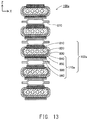
- FIG. 13 Explanatory view schematically showing the structure of a fuel cell stack 100 a according to a modification.
- FIG. 1 is a perspective view showing the external appearance of a fuel cell stack 100 according to the present embodiment
- FIG. 2 is an explanatory view showing an XZ section of the fuel cell stack 100 taken along line II-II of FIG. 1
- FIG. 3 is an explanatory view showing a YZ section of the fuel cell stack 100 taken along line III-III of FIG. 1
- FIGS. 1 to 3 show mutually orthogonal X-axis, Y-axis, and Z-axis for specifying respective directions.
- the positive Z-axis direction is called the “upward direction” and the negative Z-axis direction is called the “downward direction”; however, in actuality, the fuel cell stack 100 may be disposed in a different orientation.
- the same also applies to FIG. 4 and subsequent drawings.
- the fuel cell stack 100 includes a plurality of (seven in the present embodiment) of electricity generation units 102 and a pair of end plates 104 and 106 .
- the seven electricity generation units 102 are disposed in a predetermined direction of array (in the vertical direction in the present embodiment).
- a pair of the end plates 104 and 106 is disposed in such a manner as to hold an assembly of the seven electricity generation units 102 from the upper and lower sides thereof.
- the direction of array (vertical direction) corresponds to the first direction appearing in CLAIMS.
- the fuel cell stack 100 has a plurality (eight in the present embodiment) of holes extending in the vertical direction through peripheral portions about the Z-axis direction of its component layers (the electricity generation units 102 and the end plates 104 and 106 ).
- the corresponding holes formed in the layers communicate with one another in the vertical direction, thereby forming communication holes 108 extending in the vertical direction from one end plate 104 to the other end plate 106 .
- individual holes which constitute each communication hole 108 and are formed in the individual layers of the fuel cell stack 100 may be referred to as the “communication holes 108 .”
- Bolts 22 extending in the vertical direction are inserted into the corresponding communication holes 108 , and the fuel cell stack 100 is fastened by means of the bolts 22 and nuts 24 engaged with opposite ends of the bolts 22 .
- corresponding insulation sheets 26 intervene between the nuts 24 engaged with one ends (upper ends) of the bolts 22 and the upper surface of the end plate 104 serving as the upper end of the fuel cell stack 100 and between the nuts 24 engaged with the other ends (lower ends) of the bolts 22 and the lower surface of the end plate 106 serving as the lower end of the fuel cell stack 100 .
- the gas passage member 27 and the insulation sheets 26 disposed respectively on the upper end and on the lower end of the gas passage member 27 intervene between the nut 24 and the surface of the end plate 106 .
- the insulation sheet 26 is formed of, for example, a mica sheet, a ceramic fiber sheet, a ceramic compact sheet, a glass sheet, or a glass ceramic composite material.
- the outside diameter of a shaft portion of each bolt 22 is smaller than the inside diameter of each communication hole 108 . Accordingly, a space exists between the outer circumferential surface of the shaft portion of each bolt 22 and the inner circumferential surface of each communication hole 108 . As shown in FIGS.
- a space defined by the bolt 22 (bolt 22 A) located at around the midpoint of one side of the perimeter about the Z-axis direction of the fuel cell stack 100 (a side at the positive side in the X-axis direction of two sides in parallel with the Y-axis) and the communication hole 108 into which the bolt 22 A is inserted functions as an oxidizer gas introduction manifold 161 into which oxidizer gas OG is introduced from outside the fuel cell stack 100 and which serves as a gas flow channel for supplying the oxidizer gas OG to the electricity generation units 102
- a space defined by the bolt 22 (bolt 22 B) located at around the midpoint of the other side opposite the above side (a side at the negative side in the X-axis direction of two sides in parallel with the Y-axis) and the communication hole 108 into which the bolt 22 B is inserted functions as an oxidizer gas discharge manifold 162 from which oxidizer offgas OOG discharged from the cathode chambers 166 of the electricity
- a space defined by the bolt 22 (bolt 22 D) located at around the midpoint of one side of the perimeter about the Z-axis direction of the fuel cell stack 100 (a side at the positive side in the Y-axis direction of two sides in parallel with the X-axis) and the communication hole 108 into which the bolt 22 D is inserted functions as a fuel gas introduction manifold 171 into which fuel gas FG is introduced from outside the fuel cell stack 100 and which supplies the fuel gas FG to the electricity generation units 102
- a space defined by the bolt 22 (bolt 22 E) located at around the midpoint of the other side opposite the above side (a side at the negative side in the Y-axis direction of two sides in parallel with the X-axis) and the communication hole 108 into which the bolt 22 E is inserted functions as a fuel gas discharge manifold 172 from which fuel offgas FOG discharged from the anode chambers 176 of the electricity generation units 102 is discharged to the outside of the
- the fuel cell stack 100 has four gas passage members 27 .
- Each gas passage member 27 has a tubular body portion 28 and a tubular branch portion 29 branching from the side surface of the body portion 28 .
- the hole of the branch portion 29 communicates with the hole of the body portion 28 .
- a gas pipe (not shown) is connected to the branch portion 29 of each gas passage member 27 . As shown in FIG.
- the hole of the body portion 28 of the gas passage member 27 disposed at the position of the bolt 22 A which partially defines the oxidizer gas introduction manifold 161 communicates with the oxidizer gas introduction manifold 161
- the hole of the body portion 28 of the gas passage member 27 disposed at the position of the bolt 22 B which partially defines the oxidizer gas discharge manifold 162 communicates with the oxidizer gas discharge manifold 162 . Also, as shown in FIG.
- the hole of the body portion 28 of the gas passage member 27 disposed at the position of the bolt 22 D which partially defines the fuel gas introduction manifold 171 communicates with the fuel gas introduction manifold 171
- the hole of the body portion 28 of the gas passage member 27 disposed at the position of the bolt 22 E which partially defines the fuel gas discharge manifold 172 communicates with the fuel gas discharge manifold 172 .
- the two end plates 104 and 106 are electrically conductive members each having an approximately rectangular flat-plate shape and are formed of, for example, stainless steel.
- One end plate 104 is disposed on the uppermost electricity generation unit 102
- the other end plate 106 is disposed under the lowermost electricity generation unit 102 .
- a plurality of the electricity generation units 102 are held under pressure between the two end plates 104 and 106 .
- the upper end plate 104 functions as a positive output terminal of the fuel cell stack 100
- the lower end plate 106 functions as a negative output terminal of the fuel cell stack 100 .
- FIG. 4 is an explanatory view of the same XZ section as that of FIG. 2 , showing two adjacent electricity generation units 102
- FIG. 5 is an explanatory view of the same YZ section as that of FIG. 3 , showing two adjacent electricity generation units 102 .
- the electricity generation unit 102 includes a single cell 110 , a separator 120 , a cathode-side frame 130 , a cathode-side current collector 134 , an anode-side frame 140 , an anode-side current collector 144 , and a pair of interconnectors 150 serving as the uppermost layer and the lowermost layer of the electricity generation unit 102 .
- Holes corresponding to the communication holes 108 into which the bolts 22 are inserted are formed in peripheral portions about the Z-axis direction of the separator 120 , the cathode-side frame 130 , the anode-side frame 140 , and the interconnectors 150 .
- the interconnector 150 is an electrically conductive member having an approximately rectangular flat plate shape and is formed of, for example, ferritic stainless steel.
- the interconnector 150 secures electrical conductivity between the electricity generation units 102 and prevents mixing of reaction gases between the electricity generation units 102 .
- two electricity generation units 102 are disposed adjacent to each other, and the two adjacent electricity generation units 102 share one interconnector 150 . That is, the upper interconnector 150 of a certain electricity generation unit 102 serves as a lower interconnector 150 of the upper adjacent electricity generation unit 102 .
- the uppermost electricity generation unit 102 of the fuel cell stack 100 does not have the upper interconnector 150
- the lowermost electricity generation unit 102 does not have the lower interconnector 150 (see FIGS. 2 and 3 ).
- the single cell 110 includes an electrolyte layer 112 , an anode 116 disposed on one vertical side (lower side) of the electrolyte layer 112 , a cathode 114 disposed on the other vertical side (upper side) of the electrolyte layer 112 , and an intermediate layer 180 disposed between the electrolyte layer 112 and the cathode 114 .
- the single cell 110 of the present embodiment is an anode-support-type single cell in which the anode 116 supports the other layers of the single cell 110 (i.e., the electrolyte layer 112 , the cathode 114 , and the intermediate layer 180 ).
- the electrolyte layer 112 is a member having an approximately rectangular flat-plate shape and is formed so as to contain YSZ (yttria-stabilized zirconia), which is a solid oxide. That is, the electrolyte layer 112 contains Zr (zirconium) and Y (yttrium).
- the cathode 114 is a member having an approximately rectangular flat-plate shape. In the present embodiment, the cathode 114 includes a current collecting layer 220 , and an active layer 210 located on the lower side of the current collecting layer 220 (i.e., on the side toward the electrolyte layer 112 ) (see FIG. 6 ).
- the active layer 210 of the cathode 114 mainly functions as a site of ionization reaction of oxygen contained in the oxidizer gas OG.
- the active layer 210 is formed so as to contain LSCF (lanthanum strontium cobalt ferrite) and GDC (gadolinium-doped ceria) serving as an activation substance.
- the current collecting layer 220 of the cathode 114 mainly functions as a site of diffusing the oxidizer gas OG supplied from the cathode chamber 166 and collecting electricity obtained through electricity generation reaction.
- the current collecting layer 220 is formed so as to contain LSCF. That is, the cathode 114 contains Sr (strontium) and Co (cobalt).
- the anode 116 is a member having an approximately rectangular flat-plate shape and is formed of, for example, Ni (nickel), a cermet of Ni and ceramic powder, or an Ni-based alloy.
- the single cell 110 of the present embodiment is a solid oxide fuel cell (SOFC) containing a solid oxide as an electrolyte.
- SOFC solid oxide fuel cell
- the intermediate layer 180 is a member having an approximately rectangular flat-plate shape and is formed so as to contain GDC (gadolinium-doped ceria) and YSZ.
- GDC gallium-doped ceria
- YSZ chromium-doped ceria
- the intermediate layer 180 prevents generation of SZO of high resistance caused by reaction between Sr diffused from the cathode 114 and Zr contained in the electrolyte layer 112 .
- the structure of a portion around the intermediate layer 180 in the single cell 110 will be detailed below.
- the separator 120 is a frame member which has an approximately rectangular hole 121 formed in a central region thereof and extending therethrough in the vertical direction, and is formed of, for example, a metal. A portion of the separator 120 around the hole 121 faces a peripheral portion of the surface of the electrolyte layer 112 on the cathode 114 side.
- the separator 120 is bonded to the electrolyte layer 112 (single cell 110 ) by means of a bonding layer 124 formed of a brazing material (e.g., Ag brazing material) and disposed between the facing portion of the separator 120 and the electrolyte layer 112 .
- a brazing material e.g., Ag brazing material
- the separator 120 separates the cathode chamber 166 which faces the cathode 114 , and the anode chamber 176 which faces the anode 116 , from each other, thereby preventing gas leakage from one electrode side to the other electrode side at a peripheral portion of the single cell 110 .
- the cathode-side frame 130 is a frame member which has an approximately rectangular hole 131 formed in a central region thereof and extending therethrough in the vertical direction, and is formed of, for example, an insulator such as mica.
- the hole 131 of the cathode-side frame 130 partially constitutes the cathode chamber 166 which faces the cathode 114 .
- the cathode-side frame 130 is in contact with a peripheral portion of the surface of the separator 120 on the side opposite the electrolyte layer 112 and with a peripheral portion of the surface of the interconnector 150 on the side toward the cathode 114 .
- the cathode-side frame 130 electrically insulates the two interconnectors 150 included in the electricity generation unit 102 from each other.
- the cathode-side frame 130 has an oxidizer gas supply communication hole 132 formed therein and adapted to establish communication between the oxidizer gas introduction manifold 161 and the cathode chamber 166 , and an oxidizer gas discharge communication hole 133 formed therein and adapted to establish communication between the cathode chamber 166 and the oxidizer gas discharge manifold 162 .
- the anode-side frame 140 is a frame member which has an approximately rectangular hole 141 formed in a central region thereof and extending therethrough in the vertical direction, and is formed of, for example, a metal.
- the hole 141 of the anode-side frame 140 partially constitutes the anode chamber 176 which faces the anode 116 .
- the anode-side frame 140 is in contact with a peripheral portion of the surface of the separator 120 on the side toward the electrolyte layer 112 and with a peripheral portion of the surface of the interconnector 150 on the side toward the anode 116 .
- the anode-side frame 140 has a fuel gas supply communication hole 142 formed therein and adapted to establish communication between the fuel gas introduction manifold 171 and the anode chamber 176 , and a fuel gas discharge communication hole 143 formed therein and adapted to establish communication between the anode chamber 176 and the fuel gas discharge manifold 172 .
- the anode-side current collector 144 is disposed within the anode chamber 176 .
- the anode-side current collector 144 includes an interconnector facing portion 146 , an electrode facing portion 145 , and a connection portion 147 which connects the electrode facing portion 145 and the interconnector facing portion 146 to each other, and is formed of, for example, nickel, a nickel alloy, or stainless steel.
- the electrode facing portion 145 is in contact with the surface of the anode 116 on the side opposite the electrolyte layer 112
- the interconnector facing portion 146 is in contact with the surface of the interconnector 150 on the side toward the anode 116 .
- the interconnector facing portion 146 in the lowermost electricity generation unit 102 is in contact with the lower end plate 106 . Since the anode-side current collector 144 is thus configured, the anode-side current collector 144 electrically connects the anode 116 and the interconnector 150 (or the end plate 106 ) to each other.
- a spacer 149 formed of, for example, mica is disposed between the electrode facing portion 145 and the interconnector facing portion 146 .
- the anode-side current collector 144 follows the deformation of the electricity generation unit 102 stemming from a temperature cycle and a pressure variation of reaction gas, thereby maintaining good electrical connection between the anode 116 and the interconnector 150 (or the end plate 106 ) via the anode-side current collector 144 .
- the cathode-side current collector 134 is disposed within the cathode chamber 166 .
- the cathode-side current collector 134 is composed of a plurality of current collector elements 135 each having an approximately rectangular columnar shape and is formed of, for example, ferritic stainless steel.
- the cathode-side current collector 134 is in contact with the surface of the cathode 114 on the side opposite the electrolyte layer 112 and with the surface of the interconnector 150 on the side toward the cathode 114 .
- the cathode-side current collector 134 in the uppermost electricity generation unit 102 is in contact with the upper end plate 104 . Since the cathode-side current collector 134 is thus configured, the cathode-side current collector 134 electrically connects the cathode 114 and the interconnector 150 (or the end plate 104 ) to each other. In the present embodiment, the cathode-side current collector 134 and the interconnector 150 are integrally formed as a unitary member.
- a flat-plate-shape portion orthogonal to the vertical direction (Z-axis direction) of the unitary member functions as the interconnector 150
- a plurality of the current collector elements 135 protruding from the flat-plate-shape portion toward the cathode 114 collectively function as the cathode-side current collector 134
- the unitary member composed of the cathode-side current collector 134 and the interconnector 150 may be covered with an electrically conductive coating.
- An electrically conductive bonding layer may be provided between the cathode 114 and the cathode-side current collector 134 for bonding of the cathode 114 to the cathode-side current collector 134 .
- the oxidizer gas OG when the oxidizer gas OG is supplied through a gas pipe (not shown) connected to the branch portion 29 of the gas passage member 27 provided at the position of the oxidizer gas introduction manifold 161 , the oxidizer gas OG is supplied to the oxidizer gas introduction manifold 161 through the holes of the branch portion 29 and the body portion 28 of the gas passage member 27 and is then supplied from the oxidizer gas introduction manifold 161 to the cathode chambers 166 through the oxidizer gas supply communication holes 132 of the electricity generation units 102 . Also, as shown in FIGS.
- the single cell 110 When the oxidizer gas OG is supplied to the cathode chamber 166 of each electricity generation unit 102 , whereas the fuel gas FG is supplied to the anode chamber 176 of each electricity generation unit 102 , the single cell 110 generates electricity through the electrochemical reaction between the oxidizer gas OG and the fuel gas FG.
- the electricity generating reaction is an exothermic reaction.
- the cathode 114 of the single cell 110 is electrically connected to one interconnector 150 through the cathode-side current collector 134
- the anode 116 is electrically connected to the other interconnector 150 through the anode-side current collector 144 .
- a plurality of the electricity generation units 102 contained in the fuel cell stack 100 are connected electrically in series. Accordingly, electric energy generated in the electricity generation units 102 is output from the end plates 104 and 106 which function as output terminals of the fuel cell stack 100 .
- the fuel cell stack 100 may be heated by a heater (not shown) from startup until the high temperature can be maintained by means of heat generated as a result of generation of electricity.
- the oxidizer offgas OOG discharged from the cathode chambers 166 of the electricity generation units 102 is discharged to the oxidizer gas discharge manifold 162 through the oxidizer gas discharge communication holes 133 , passes through the holes of the body portion 28 and the branch portion 29 of the gas passage member 27 provided at the position of the oxidizer gas discharge manifold 162 , and is then discharged to the outside of the fuel cell stack 100 through a gas pipe (not shown) connected to the branch portion 29 . Also, as shown in FIGS.
- the fuel offgas FOG discharged from the anode chambers 176 of the electricity generation units 102 is discharged to the fuel gas discharge manifold 172 through the fuel gas discharge communication holes 143 , passes through the holes of the body portion 28 and the branch portion 29 of the gas passage member 27 provided at the position of the fuel gas discharge manifold 172 , and is then discharged to the outside of the fuel cell stack 100 through a gas pipe (not shown) connected to the branch portion 29 .
- FIG. 6 is an explanatory view showing the specific structure of a portion of the single cell 110 around the intermediate layer 180 .
- FIG. 6 illustrates an XZ section of the single cell 110 in a region (region X 1 in FIG. 4 ) including a portion of the electrolyte layer 112 and a portion of the cathode 114 with the intermediate layer 180 intervening therebetween.
- the single cell 110 includes the intermediate layer 180 containing GDC and YSZ and disposed between (the active layer 210 ) of the cathode 114 containing LSCF and the electrolyte layer 112 containing YSZ.
- the intermediate layer 180 includes a solid solution layer 182 .
- the solid solution layer 182 is formed through, for example, interdiffusion between the intermediate layer 180 and the electrolyte layer 112 during firing of the intermediate layer 180 .
- the solid solution layer 182 is present in a region of the intermediate layer 180 adjacent to the boundary between the intermediate layer 180 and the electrolyte layer 112 .
- the solid solution layer 182 which is formed through interdiffusion between the intermediate layer 180 and the electrolyte layer 112 , contains GDC and YSZ. Thus, the solid solution layer 182 contains Gd (gadolinium), Ce (cerium), and Zr.
- SZO i.e., a substance of high resistance
- SZO is generated through diffusion of Sr contained in the cathode 114 toward the electrolyte layer 112 and reaction between the diffused Sr and Zr during, for example, firing of the cathode 114 or electricity generation operation.
- the generation of SZO causes an increase in the electric resistance of the single cell 110 , resulting in impairment of electricity generation performance.
- the intermediate layer 180 prevents diffusion of Sr from the cathode 114 toward the electrolyte layer 112 , thereby preventing generation of SZO.
- the single cell 110 forming the fuel cell stack 100 of the present embodiment is characterized by the amount of SZO and the thickness Ts of the solid solution layer 182 .
- Next will be described the performance evaluation carried out by using a plurality of samples of the single cell 110 with different SZO amounts and different thicknesses Ts of the solid solution layer 182 .
- FIG. 7 is an explanatory table showing the results of the performance evaluation. As shown in FIG. 7 , the samples exhibit different SZO amounts and different thicknesses Ts of the solid solution layer 182 . In the performance evaluation, the amount of SZO contained in the single cell 110 is indicated by “SZO (SrZrO 3 ) integrated value Vs.” A larger SZO integrated value Vs indicates a larger amount of SZO contained in the single cell 110 . The SZO integrated value Vs is calculated as detailed in “A-5. Method for analysis of single cell 110 .”
- Each sample of the single cell 110 was produced by the method described below.
- the performance evaluation involved the use of a plurality of samples of the single cell 110 with different SZO integrated values Vs and different thicknesses Ts of the solid solution layer 182 .
- the Zr content of the intermediate layer 180 is adjusted to fall within a range of 0.015 to 1 (wt %), and the intermediate layer 180 and the cathode 114 are fired at different temperatures.
- YSZ powder is mixed with a butyral resin, dioctyl phthalate (DOP) serving as a plasticizer, a dispersant, and a solvent mixture of toluene and ethanol by means of a ball mill, to thereby prepare a slurry.
- DOP dioctyl phthalate
- the resultant slurry is formed into a thin film by means of doctor blading, to thereby prepare a green sheet for an electrolyte layer having a thickness of, for example, about 10 ⁇ m.
- NiO powder is weighed (55 parts by mass in terms of Ni) and mixed with YSZ powder (45 parts by mass), to thereby prepare a powder mixture.
- the powder mixture is mixed with a butyral resin, DOP serving as a plasticizer, a dispersant, and a solvent mixture of toluene and ethanol by means of a ball mill, to thereby prepare a slurry.
- the resultant slurry is formed into a thin film by means of doctor blading, to thereby prepare a green sheet for an anode having a thickness of, for example, 270 ⁇ m.
- the green sheet for an electrolyte layer and the green sheet for an anode are attached together and dried, followed by firing at, for example, 1,400° C., to thereby prepare a laminate of the electrolyte layer 112 and the anode 116 .
- This dispersion mixing is performed so that the BET specific surface area of the resultant powder mixture becomes a predetermined value determined for each sample within a range of 13 to 23 m 2 /g.
- the powder mixture is mixed with poly(vinyl alcohol) serving as an organic binder and butyl carbitol serving as an organic solvent, and then the viscosity of the mixture is adjusted, to thereby prepare a paste for an intermediate layer.
- the paste for an intermediate layer is applied, by means of screen printing, onto the surface of the electrolyte layer 112 of the aforementioned laminate (composed of the electrolyte layer 112 and the anode 116 ), followed by firing at 1,100° C. to 1,400° C. for each sample.
- the intermediate layer 180 is formed to thereby prepare a laminate of the intermediate layer 180 , the electrolyte layer 112 , and the anode 116 .
- interdiffusion occurs between the intermediate layer 180 and the electrolyte layer 112 , to thereby form the solid solution layer 182 in a region of the intermediate layer 180 adjacent to the boundary between the intermediate layer 180 and the electrolyte layer 112 .
- LSCF powder, GDC powder, alumina powder, poly(vinyl alcohol) serving as an organic binder, and butyl carbitol serving as an organic solvent are mixed together, and the viscosity of the mixture is adjusted, to thereby prepare a paste for a cathode active layer.
- the paste for a cathode active layer is applied, by means of screen printing, onto the surface of the intermediate layer 180 of the aforementioned laminate (composed of the intermediate layer 180 , the electrolyte layer 112 , and the anode 116 ) and then dried.
- LSCF powder, alumina powder, poly(vinyl alcohol) serving as an organic binder, and butyl carbitol serving as an organic solvent are mixed together, and the viscosity of the mixture is adjusted, to thereby prepare a paste for a cathode current collecting layer.
- the paste for a cathode current collecting layer is applied onto the paste for a cathode active layer by means of screen printing and then dried, followed by firing for each sample (specifically, firing at 1,100° C. for samples S 1 to S 10 , and firing at 1,000° C. for sample S 11 ).
- firing for each sample specifically, firing at 1,100° C. for samples S 1 to S 10 , and firing at 1,000° C. for sample S 11 .
- the active layer 210 and the current collecting layer 220 of the cathode 114 are formed.
- the single cell 110 having the aforementioned structure is produced through the above-described process.
- the present performance evaluation involved examination of the adhesion of the cathode 114 and the electricity generation performance of the single cell 110 .
- the initial voltage of each sample of the single cell 110 was measured at a current density of 0.55 A/cm 2 under the following conditions: temperature: 700° C., atmosphere: hydrogen (320 mL), and dew-point temperature: 30° C.
- a sample was determined to be unacceptable (X) in the case where separation of the cathode 114 occurred in the evaluation of the adhesion of the cathode 114 , or the initial voltage was less than 0.90 V in the evaluation of the electricity generation performance of single cell 110 .
- the sample was determined to be acceptable (O) in the other cases.
- sample S 11 was determined to be unacceptable because of occurrence of separation of the cathode 114 .
- the firing temperature of the cathode 114 (1,000° C.) in sample S 11 is lower than that in the other samples, and thus diffusion of Sr contained in the cathode 114 is reduced, resulting in a very small SZO integrated value Vs.
- the low firing temperature of the cathode 114 in sample S 11 probably causes weak bonding between the cathode 114 and the intermediate layer 180 , resulting in separation of the cathode 114 .
- the SZO integrated value Vs is preferably larger than 209. No separation of the cathode 114 occurred in the other samples.
- FIG. 8 is an explanatory graph showing the relationship between SZO integrated value Vs and the thickness Ts of the solid solution layer 182 in samples (except for sample S 11 , the same shall apply in FIGS. 9 and 10 ).
- FIG. 9 is an explanatory graph showing the relationship between SZO integrated value Vs and initial voltage.
- FIG. 10 is an explanatory graph showing the relationship between the thickness Ts of the solid solution layer 182 and initial voltage.
- the smaller the thickness Ts of the solid solution layer 182 the larger the SZO integrated value Vs
- the larger the thickness Ts of the solid solution layer 182 the smaller the SZO integrated value Vs.
- an SZO integrated value Vs falling within a specific range led to a high initial voltage
- an SZO integrated value Vs below or above the range led to a low initial voltage
- a thickness Ts of the solid solution layer 182 falling within a specific range led to a high initial voltage
- a thickness Ts of the solid solution layer 182 below or above the range led to a low initial voltage.
- the reason for this is probably as follows. Excessively large SZO integrated value Vs (i.e., excessively small thickness Ts of the solid solution layer 182 ) leads to low electric resistance of the solid solution layer 182 but very high electric resistance caused by SZO, resulting in high electric resistance of the single cell 110 .
- the thickness Ts of the solid solution layer 182 was very large.
- the solid solution layer 182 exhibited very high electric resistance, and the single cell 110 exhibited high electric resistance. This probably causes low initial voltage.
- the thickness Ts of the solid solution layer 182 was very small, resulting in very large SZO integrated value Vs.
- SZO caused very high electric resistance, and the single cell 110 exhibited high electric resistance. This probably causes low initial voltage.
- samples S 2 to S 9 In contrast, in samples S 2 to S 9 , the initial voltage was 0.90 V or more, and no separation of the cathode 114 occurred as described above. Thus, samples S 2 to S 9 were determined to be acceptable. In samples S 2 to S 9 , the SZO integrated value Vs and the thickness Ts of the solid solution layer 182 fall within ranges so as to achieve a good balance between low electric resistance caused by SZO and low electric resistance of the solid solution layer 182 . This probably causes low electric resistance of the single cell 110 and prevents a decrease in initial voltage.
- the initial voltage was 0.91 V or more; i.e., particularly preferred electricity generation performance was achieved.
- the SZO integrated value Vs and the thickness Ts of the solid solution layer 182 fall within particularly preferred ranges.
- the initial voltage was 0.92 V or more; i.e., further preferred electricity generation performance was achieved.
- the SZO integrated value Vs and the thickness Ts of the solid solution layer 182 fall within still more preferred ranges.
- intersection points between an approximate curve AC 1 prepared by plotting of data and each of horizontal lines corresponding to initial voltages of 0.90, 0.91, and 0.92 V indicate the following relations: the initial voltage is 0.90 V or more when the SZO integrated value Vs falls within a range of 600 to 10,300; the initial voltage is 0.91 V or more when the SZO integrated value Vs falls within a range of 1,600 to 9,200; and the initial voltage is 0.92 V or more when the SZO integrated value Vs falls within a range of 3,100 to 7,800.
- the SZO integrated value Vs preferably falls within a range of 600 to 10,300, since impairment of electricity generation performance can be prevented while preventing separation between the intermediate layer 180 and the cathode 114 .
- the SZO integrated value Vs more preferably falls within a range of 1,600 to 9,200, since impairment of electricity generation performance can be effectively prevented while preventing separation between the intermediate layer 180 and the cathode 114 .
- the SZO integrated value Vs still more preferably falls within a range of 3,100 to 7,800, since impairment of electricity generation performance can be more effectively prevented while preventing separation between the intermediate layer 180 and the cathode 114 .
- intersection points between an approximate curve AC 2 prepared by plotting of data and each of horizontal lines corresponding to initial voltages of 0.90, 0.91, and 0.92 V indicate the following relations: the initial voltage is 0.90 V or more when the thickness Ts of the solid solution layer 182 falls within a range of 0.246 ⁇ m to 0.482 ⁇ m; the initial voltage is 0.91 V or more when the thickness Ts of the solid solution layer 182 falls within a range of 0.271 ⁇ m to 0.457 ⁇ m; and the initial voltage is 0.92 V or more when the thickness Ts of the solid solution layer 182 falls within a range of 0.307 ⁇ m to 0.422 ⁇ m.
- the thickness Ts of the solid solution layer 182 preferably falls within a range of 0.246 ⁇ m to 0.482 ⁇ m, since an increase in the thickness Ts of the solid solution layer 182 to a certain extent can prevent impairment of electricity generation performance caused by SZO while preventing impairment of electricity generation performance due to an excessive increase in the thickness Ts of the solid solution layer 182 of high resistance.
- the thickness Ts of the solid solution layer 182 more preferably falls within a range of 0.271 ⁇ m to 0.457 ⁇ m, since an increase in the thickness Ts of the solid solution layer 182 to a certain extent can effectively prevent impairment of electricity generation performance caused by SZO while effectively preventing impairment of electricity generation performance due to an excessive increase in the thickness Ts of the solid solution layer 182 of high resistance.
- the thickness Ts of the solid solution layer 182 still more preferably falls within a range of 0.307 ⁇ m to 0.422 ⁇ m, since an increase in the thickness Ts of the solid solution layer 182 to a certain extent can more effectively prevent impairment of electricity generation performance caused by SZO while more effectively preventing impairment of electricity generation performance due to an excessive increase in the thickness Ts of the solid solution layer 182 of high resistance.
- FIG. 11 is an explanatory illustration showing a method for calculation of SZO integrated value Vs.
- a cross section parallel to the Z-axis direction e.g., an XZ section
- a 20 ⁇ m ⁇ 20 ⁇ m rectangular field of view FOVa is determined in the exposed cross section.
- the rectangular field of view FOVa is determined so as to include at least a portion of the cathode 114 in the first direction (Z-axis direction), the intermediate layer 180 , and at least a portion of the electrolyte layer 112 in the first direction (i.e., so as to include the boundary B 1 between the cathode 114 and the intermediate layer 180 and the boundary B 3 between the intermediate layer 180 and the electrolyte layer 112 ). Also, the rectangular field of view FOVa is determined such that two sides (top side St and bottom side Sb) of the four sides forming the rectangular field of view FOVa are approximately parallel to the boundary B 3 between the intermediate layer 180 and the electrolyte layer 112 .
- the term “approximately parallel” refers to the case where two lines (or two faces) form an angle X (0° ⁇ X ⁇ 90°) of 20 or less, and the term “approximately orthogonal” refers to the case where two lines (or two faces) form an angle X of 88° or more.
- the rectangular field of view FOVa is divided into 256 ⁇ 256 pixels, and Sr intensity mapping data ID representing Sr intensities I (sr) in the pixels are generated by means of EPMA (electron probe micro analyzer) mapping.
- EPMA electron probe micro analyzer
- the peak intensities of Sr characteristic X-rays are measured in count units by means of, for example, FE-EPMA JXA-8500F (manufactured by JEOL Ltd.) (electron beams applied to a measurement sample are accelerated at 15 kV) under the following conditions: irradiation current: 20 nA, mapping area: 20 ⁇ m square, 256 pixels ⁇ 256 pixels.
- the measuring time for characteristic X-rays is 30 milliseconds in each pixel.
- PETH is used as a dispersive crystal for isolation of Sr characteristic X-ray.
- an Sr intensity line integrated value ⁇ I(L) which is the integrated value of Sr intensities I (sr) in pixels, is calculated in each of 256 pixel lines L(n) (L(1) to L(256)) approximately orthogonal to the Z-axis direction in the Sr intensity mapping data ID.
- an Sr intensity curve IC exhibiting Sr intensities at different positions in the Z-axis direction is obtained as exemplified in the lower part of FIG. 11 , in which the horizontal axis shows the Sr intensity line integrated value ⁇ I(L) and the vertical axis shows the position of each pixel line L(n).
- the Sr intensity curve IC is obtained by plotting the Sr intensity line integrated value ⁇ I(L) against each pixel line L(n).
- the Sr intensity curve IC is a curve smoothly connecting 256 points corresponding to the Sr intensity line integrated values ⁇ I(L) of the 256 pixel lines L(n).
- the cathode 114 is formed so as to contain LSCF, and thus the cathode 114 contains Sr in an amount larger than that of Sr contained in the material for forming the electrolyte layer 112 or the intermediate layer 180 .
- the Sr intensity line integrated value ⁇ I(L) indicated by the Sr intensity curve IC is large in the cathode 114 position (upper position). In this position, Sr is probably present mainly in the form of LSCF.
- the diffusion of Sr contained in the cathode 114 toward the electrolyte layer 112 causes reaction between the diffused Sr and Zr contained in the electrolyte layer 112 , to thereby generate SZO.
- the Sr intensity line integrated value ⁇ I(L) indicated by the Sr intensity curve IC decreases to a low level from the cathode 114 position toward the electrolyte layer 112 side (lower side), increases again from the low level to a high level, and then decreases from the high level to a low level.
- Sr is present mainly in the form of SZO in a portion where “the Sr intensity line integrated value increases again from the low level to a high level.”
- the Sr intensity in this position probably correlates with the amount of SZO. Therefore, the SZO integrated value Vs, which is an index of the amount of SZO, is calculated as described below.
- an electrolyte layer integrated value portion PAe, a first integrated value portion PA 1 , and a second integrated value portion PA 2 are specified in the Sr intensity curve IC.
- the electrolyte layer integrated value portion PAe exhibits the Sr intensity line integrated value ⁇ I(L) of a portion of the electrolyte layer 112 having an approximately uniform and small Sr intensity line integrated value ⁇ I(L).
- the electrolyte layer integrated value portion PAe corresponds to a small Sr intensity line integrated value ⁇ I(L) portion (trough) in the lowermost portion of the Sr intensity curve IC shown in the lower part of FIG. 11 .
- the first integrated value portion PA 1 exhibits an Sr intensity line integrated value ⁇ I(L) approximately equal to the Sr intensity line integrated value ⁇ I(L) of the electrolyte layer integrated value portion PAe.
- the first integrated value portion PA 1 corresponds to a small Sr intensity line integrated value ⁇ I(L) portion (trough) at a position (just below the cathode 114 ) of the Sr intensity curve IC shown in the lower part of FIG. 11 .
- the expression “two Sr intensity line integrated values ⁇ I(L) are approximately equal to each other” refers to the case where one of the Sr intensity line integrated values ⁇ I(L) is 90% to 110% of the other Sr intensity line integrated value ⁇ I(L).
- the second integrated value portion PA 2 is located between the electrolyte layer integrated value portion PAe and the first integrated value portion PA 1 and exhibits an Sr intensity line integrated value ⁇ I(L) larger than the Sr intensity line integrated value ⁇ I(L) of the electrolyte layer integrated value portion PAe.
- the second integrated value portion PA 2 corresponds to a peak portion sandwiched between the two troughs (i.e., the electrolyte layer integrated value portion PAe and the first integrated value portion PA 1 ) of the Sr intensity curve IC shown in the lower part of FIG. 11 .
- a peak pixel line Lp is specified which is a pixel line L(n) at which the Sr intensity line integrated value ⁇ I(L) is maximum.
- a first point PO 1 and a second point PO 2 are also specified, wherein the first point PO 1 corresponds to the minimum Sr intensity line integrated value ⁇ I(L) on the electrolyte layer 112 side with respect to the peak pixel line Lp, and the second point PO 2 corresponds to the minimum Sr intensity line integrated value ⁇ I(L) on the cathode 114 side with respect to the peak pixel line Lp.
- a straight base line BL is drawn by connecting the first point PO 1 and the second point PO 2 , and the area of a region surrounded by the base line BL and the second integrated value portion PA 2 of the Sr intensity curve IC (i.e., a hatched region in the lower part of FIG. 11 ) is calculated as the SZO integrated value Vs in the rectangular field of view FOVa.
- FIG. 12 is an explanatory view showing a method for determination of the thickness Ts of the solid solution layer 182 .
- a cross section parallel to the Z-axis direction (e.g., an XZ section) is exposed, and a rectangular field of view FOVb is determined in the exposed cross section.
- the rectangular field of view FOVb is appropriately determined such that the center of the field of view FOVb is located at a position assumed to be the boundary B 3 between the electrolyte layer 112 and the intermediate layer 180 .
- a line segment SL is determined so as to be approximately orthogonal to the boundary B 3 .
- the line segment SL intersects with the outer periphery of the rectangular field of view FOVb.
- the line segment SL is divided into 500 pixels, and intensity data exhibiting Gd (or Sm, the same shall apply hereinafter) and Ce intensities in the pixels are prepared by means of EPMA mapping.
- the peak intensities of Gd and Ce characteristic X-rays are measured in count units by means of, for example, FE-EPMA JXA-8500F (manufactured by JEOL Ltd.) (electron beams applied to a measurement sample are accelerated at 15 kV) under the following conditions: irradiation current: 20 nA, line length: 3.61 ⁇ m, 500 pixels.
- the measuring time for characteristic X-rays is 500 milliseconds in each pixel.
- LIFH is used as a dispersive crystal for isolation of Gd characteristic X-ray
- PET is used as a dispersive crystal for isolation of Ce characteristic X-ray.
- the Gd and Ce intensity data are smoothed (10-point average).
- the average of the intensities in the first to 61st pixels of the 500 pixels on the line segment SL is defined to correspond to a concentration of 100%
- the average of the intensities in the 406th to 491st pixels of the 500 pixels on the line segment SL is defined to correspond to a concentration of 0%.
- the intensity in each pixel is converted into a concentration.
- the lower part of FIG. 12 shows exemplary Gd and Ce concentrations obtained through the conversion.
- the lower part of FIG. 12 also shows Zr concentration.
- the position at which the Ce concentration is 60% is defined as the boundary B 2 on the upper side (the cathode 114 side) of the solid solution layer 182
- the position at which the Gd concentration is 40% is defined as the boundary B 3 on the lower side (the electrolyte layer 112 side) of the solid solution layer 182 .
- the distance between the boundary B 2 and the boundary B 3 is determined as the thickness Ts of the solid solution layer 182 in the rectangular field of view FOVb.
- 10 rectangular fields of view FOVb are determined such that they do not overlap with one another, and the thickness Ts of the solid solution layer 182 is determined in each rectangular field of view FOVb as described above.
- the average of the thicknesses Ts of the solid solution layer 182 in the rectangular fields of view FOVb is defined as the thickness Ts of the solid solution layer 182 of the single cell 110 .
- the configuration of the single cell 110 or the fuel cell stack 100 in the above embodiment is a mere example, and may be modified into various forms.
- the cathode 114 has a two-layer structure including the active layer 210 and the current collecting layer 220 .
- the cathode 114 may include an additional layer besides the active layer 210 and the current collecting layer 220 , or the cathode 114 may have a single-layer structure.
- the number of the single cells 110 included in the fuel cell stack 100 is a mere example and is determined as appropriate in accordance with, for example, a required output voltage of the fuel cell stack 100 .
- the electrolyte layer 112 contains YSZ in the above embodiment. So long as the electrolyte layer 112 contains Zr and at least one of Y, Sc (scandium), and Ca (calcium), the electrolyte layer 112 may contain, for example, a material such as ScSZ (scandia-stabilized zirconia) or CaSZ (calcium oxide-stabilized zirconia) in place of or in addition to YSZ.
- the cathode 114 (the active layer 210 and the current collecting layer 220 ) contains LSCF.
- the cathode 114 may contain another material in place of or in addition to LSCF.
- a portion of the intermediate layer 180 other than the solid solution layer 182 contains GDC and YSZ.
- a portion of the intermediate layer 180 other than the solid solution layer 182 may contain, for example, a material such as SDC (samarium-doped ceria) in place of or in addition to GDC, and may contain, for example, a material such as ScSZ or CaSZ in place of or in addition to YSZ.
- the material forming the solid solution layer 182 may vary depending on the materials forming the intermediate layer 180 and the electrolyte layer 112 .
- the solid solution layer 182 is formed so as to contain at least one of Gd and Sm (samarium), Ce, and Zr.
- the SZO integrated value Vs or the thickness Ts of the solid solution layer 182 does not necessarily fall within the aforementioned preferred range in all the single cells 110 included in the fuel cell stack 100 . So long as the SZO integrated value Vs or the thickness Ts of the solid solution layer 182 falls within the aforementioned preferred range in at least one single cell 110 included in the fuel cell stack 100 , impairment of electricity generation performance can be prevented while preventing separation between the intermediate layer 180 and the cathode 114 in the single cell 110 .
- the fuel cell stack 100 includes a plurality of single cells 110 having a flat-plate shape.
- the present invention is also applicable to another configuration, for example, a fuel cell stack 100 a including a plurality of approximately cylindrical single cells 110 a as disclosed in International Patent Publication WO 2012/165409.
- FIG. 13 is an explanatory view schematically showing the structure of a fuel cell stack 100 a according to a modification.
- the fuel cell stack 100 a according to the modification includes a plurality of electricity generation units 102 a disposed at predetermined intervals in the Z-axis direction.
- the electricity generation units 102 a are connected electrically in series through current collecting members 870 each intervening between two adjacent electricity generation units 102 a .
- Each electricity generation unit 102 a has a flattened columnar external appearance and includes an electrode support 830 , a single cell 110 a , and an interconnector 810 .
- the single cell 110 a includes an anode 840 , an electrolyte layer 850 , a cathode 860 , and an intermediate layer 900 .
- the Z-axis direction in the modification shown in FIG. 13 corresponds to the first direction appearing in CLAIMS.
- the electrode support 830 is a columnar body having an approximately elliptical cross section and is formed of a porous material.
- the electrode support 830 has in the interior thereof a plurality of fuel gas flow channels 820 extending in the longitudinal direction of the columnar body.
- the anode 840 is disposed so as to partially cover the side surface of the electrode support 830 .
- the anode 840 covers one of the paired parallel flat surfaces of the electrode support 830 and two curved surfaces thereof connecting the ends of the flat surfaces.
- the electrolyte layer 850 is disposed so as to cover the entire side surface of the anode 840 .
- the cathode 860 is disposed so as to cover a region of the side surface of the electrolyte layer 850 , the region being located on the flat surface of the electrode support 830 .
- the intermediate layer 900 is disposed between the electrolyte layer 850 and the cathode 860 .
- a solid solution layer (not shown) formed through interdiffusion between the intermediate layer 900 and the electrolyte layer 850 is present in a region of the intermediate layer 900 adjacent to the boundary between the intermediate layer 900 and the electrolyte layer 850 .
- the interconnector 810 is disposed on the flat surface of the electrode support 830 on which the anode 840 and the electrolyte layer 850 are not disposed.
- Each current collecting member 870 electrically connects the cathode 860 of one electricity generation unit 102 a to the interconnector 810 of another adjacent electricity generation unit 102 a .
- An oxidizer gas is supplied to the outside of the cathode 860 , and a fuel gas is supplied to the fuel gas flow channels 820 formed in the electrode support 830 . Electricity is generated in the fuel cell stack 100 a when it is heated to a predetermined operation temperature.
- the SZO integrated value Vs preferably falls within a range of 600 to 10,300 in at least one single cell 110 a as in the case of the above embodiment, since impairment of electricity generation performance can be prevented while preventing separation between the intermediate layer 900 and the cathode 860 .
- the solid solution layer preferably has a thickness of 0.246 ⁇ m to 0.482 ⁇ m, since an increase in the thickness of the solid solution layer to a certain extent can prevent impairment of electricity generation performance caused by SZO while preventing impairment of electricity generation performance due to an excessive increase in the thickness of the solid solution layer of high resistance.
- the above embodiment refers to an SOFC for generating electricity by utilizing the electrochemical reaction between hydrogen contained in a fuel gas and oxygen contained in an oxidizer gas; however, the present invention is also applicable to an electrolysis single cell which is the constitutive unit of a solid oxide electrolysis cell (SOEC) for generating hydrogen by utilizing the electrolysis of water, and to an electrolysis cell stack including a plurality of electrolysis single cells. Since the structure of the electrolysis cell stack is publicly known as described in, for example, Japanese Patent Application Laid-Open (kokai) No. 2016-81813, detailed description of the structure is omitted. Schematically, the electrolysis cell stack has a structure similar to that of the fuel cell stack 100 in the above embodiment.
- SOEC solid oxide electrolysis cell
- the fuel cell stack 100 in the above embodiment may be read as “electrolysis cell stack,” the electricity generation unit 102 may be read as “electrolysis cell unit,” and the single cell 110 may be read as “electrolysis single cell.”
- voltage is applied between the cathode 114 and the anode 116 such that the cathode 114 serves as a positive electrode, whereas the anode 116 serves as a negative electrode, and water vapor is supplied as a material gas through the communication hole 108 .
- the electrolysis of water occurs in the electrolysis cell units, whereby hydrogen gas is generated in the anode chambers 176 , and hydrogen is discharged to the outside of the electrolysis cell stack through the communication hole 108 .
- the electrolysis single cell and the electrolysis cell stack having the aforementioned configuration if an intermediate layer is disposed between the electrolyte layer and the cathode, and the SZO integrated value Vs is adjusted to fall within a range of 600 to 10,300 as in the case of the above embodiment, performance impairment can be prevented while preventing separation between the intermediate layer and the cathode.
- the thickness of a solid solution layer formed in a region of the intermediate layer adjacent to the boundary between the intermediate layer and the electrolyte layer is adjusted to be 0.246 ⁇ m to 0.482 ⁇ m, an increase in the thickness of the solid solution layer to a certain extent can prevent performance impairment caused by SZO while preventing performance impairment due to an excessive increase in the thickness of the solid solution layer of high resistance.
- SOFC solid oxide fuel cell
- MCFC molten carbonate fuel cell
Landscapes
- Chemical & Material Sciences (AREA)
- Engineering & Computer Science (AREA)
- Chemical Kinetics & Catalysis (AREA)
- Electrochemistry (AREA)
- Manufacturing & Machinery (AREA)
- General Chemical & Material Sciences (AREA)
- Sustainable Development (AREA)
- Sustainable Energy (AREA)
- Life Sciences & Earth Sciences (AREA)
- Materials Engineering (AREA)
- Metallurgy (AREA)
- Organic Chemistry (AREA)
- Inorganic Chemistry (AREA)
- Fuel Cell (AREA)
- Inert Electrodes (AREA)
Abstract
Description
- Patent Document 1: Japanese Patent Application Laid-Open (kokai) No. 2014-60161
(3) In the above-described electrochemical reaction unit, the SrZrO3 integrated value in at least one cross section parallel to the first direction may be 1,600 to 9,200. In the present electrochemical reaction single cell, the SrZrO3 integrated value is 9,200 or less. This can effectively prevent impairment of the performance of the electrochemical reaction single cell, which would otherwise occur due to deposition of SrZrO3. In the present electrochemical reaction single cell, the SrZrO3 integrated value is 1,600 or more, and thus separation between the intermediate layer and the cathode can be effectively prevented.
(4) In the above-described electrochemical reaction single cell, the intermediate layer may include a solid solution layer containing at least one of Gd and Sm, Ce, and Zr, and the solid solution layer may have a thickness of 0.271 μm to 0.457 μm. This configuration of the present electrochemical reaction single cell can effectively prevent impairment of the performance of the electrochemical reaction single cell, which would otherwise occur due to an excessive increase in the thickness of the solid solution layer of high resistance. In addition, impairment of the performance of the electrochemical reaction single cell due to an increase in SrZrO3 integrated value can be prevented effectively by increasing the thickness of the solid solution layer to a certain extent.
(5) In the above-described electrochemical reaction single cell, the SrZrO3 integrated value in at least one cross section parallel to the first direction may be 3,100 to 7,800. In the present electrochemical reaction single cell, the SrZrO3 integrated value is 7,800 or less. This can more effectively prevent impairment of the performance of the electrochemical reaction single cell, which would otherwise occur due to deposition of SrZrO3. In the present electrochemical reaction single cell, the SrZrO3 integrated value is 3,100 or more, and thus separation between the intermediate layer and the cathode can be more effectively prevented.
(6) In the above-described electrochemical reaction single cell, the intermediate layer may include a solid solution layer containing at least one of Gd and Sm, Ce, and Zr, and the solid solution layer may have a thickness of 0.307 μm to 0.422 μm. This configuration of the present electrochemical reaction single cell can more effectively prevent impairment of the performance of the electrochemical reaction single cell, which would otherwise occur due to an excessive increase in the thickness of the solid solution layer of high resistance. In addition, impairment of the performance of the electrochemical reaction single cell due to an increase in SrZrO3 integrated value can be prevented more effectively by increasing the thickness of the solid solution layer to a certain extent.
(7) In the above-described electrochemical reaction single cell, the electrolyte layer may contain a solid oxide. The configuration of the present electrochemical reaction single cell can prevent impairment of the performance of the single cell due to deposition of SrZrO3, even in the case where the impairment of the performance of the single cell due to deposition of SrZrO3 is likely to occur.
(8) In the above-described electrochemical reaction single cell, the electrochemical reaction single cell may be a fuel cell single cell. According to the present electrochemical reaction single cell, impairment of electricity generation performance, which would otherwise occur due to deposition of SrZrO3, can be prevented.
Claims (9)
Applications Claiming Priority (4)
| Application Number | Priority Date | Filing Date | Title |
|---|---|---|---|
| JP2017-026544 | 2017-02-16 | ||
| JPJP2017-026544 | 2017-02-16 | ||
| JP2017026544A JP6290471B1 (en) | 2017-02-16 | 2017-02-16 | Electrochemical reaction cell and electrochemical reaction cell stack |
| PCT/JP2017/041020 WO2018150664A1 (en) | 2017-02-16 | 2017-11-15 | Electrochemical reaction single cell and electrochemical reaction cell stack |
Publications (2)
| Publication Number | Publication Date |
|---|---|
| US20190372144A1 US20190372144A1 (en) | 2019-12-05 |
| US11223060B2 true US11223060B2 (en) | 2022-01-11 |
Family
ID=61557993
Family Applications (1)
| Application Number | Title | Priority Date | Filing Date |
|---|---|---|---|
| US16/485,557 Active 2038-03-01 US11223060B2 (en) | 2017-02-16 | 2017-11-15 | Electrochemical reaction single cell and electrochemical reaction cell stack |
Country Status (6)
| Country | Link |
|---|---|
| US (1) | US11223060B2 (en) |
| EP (1) | EP3584864A4 (en) |
| JP (1) | JP6290471B1 (en) |
| KR (1) | KR102239403B1 (en) |
| CN (1) | CN110337748B (en) |
| WO (1) | WO2018150664A1 (en) |
Cited By (1)
| Publication number | Priority date | Publication date | Assignee | Title |
|---|---|---|---|---|
| USD954712S1 (en) * | 2018-12-12 | 2022-06-14 | Micron Technology, Inc. | Thermal control component |
Families Citing this family (4)
| Publication number | Priority date | Publication date | Assignee | Title |
|---|---|---|---|---|
| WO2019240297A1 (en) * | 2018-06-15 | 2019-12-19 | 京セラ株式会社 | Cell, cell stack device, module, and module storage device |
| JP7452462B2 (en) * | 2021-02-18 | 2024-03-19 | トヨタ自動車株式会社 | Fuel cell stack manufacturing method and manufacturing device |
| WO2025249470A1 (en) * | 2024-05-30 | 2025-12-04 | 日本特殊陶業株式会社 | Electrochemical cell, solid oxide electrolysis cell, cell stack, hot module, and hydrogen production device |
| WO2025249472A1 (en) * | 2024-05-30 | 2025-12-04 | 日本特殊陶業株式会社 | Electrochemical cell, solid oxide electrolysis cell, cell stack, hot module, and hydrogen production device |
Citations (9)
| Publication number | Priority date | Publication date | Assignee | Title |
|---|---|---|---|---|
| US20110195343A1 (en) | 2008-10-09 | 2011-08-11 | Ceramic Fuel Cells Limited | Solid oxide fuel cell or solid oxide fuel cell sub-component and methods of preparing same |
| US20130011768A1 (en) | 2011-06-29 | 2013-01-10 | Syracuse University | High Performance Flame Fuel Cell Using an Anode Supported Solid-Oxide Fuel Cell |
| JP2013041809A (en) | 2011-07-21 | 2013-02-28 | Ngk Insulators Ltd | Fuel cell |
| KR20130052286A (en) | 2011-11-11 | 2013-05-22 | 한국과학기술연구원 | Fabrication and structure of low- and intermediate-temperature-operating solid oxide fuel cell by spin coating and low-temperature sintering |
| JP2014026926A (en) | 2012-07-30 | 2014-02-06 | Kyocera Corp | Solid oxide fuel cell and cell stack device and fuel cell module |
| US20140322633A1 (en) * | 2011-12-09 | 2014-10-30 | Posco | Solid oxide fuel cell comprising reaction preventing layer and method for manufacturing same |
| EP3021393A1 (en) | 2013-07-11 | 2016-05-18 | NGK Sparkplug Co., Ltd. | Solid oxide fuel cell, manufacturing method therefor, fuel-cell stack, and solid oxide fuel-cell device |
| JP2016126984A (en) | 2015-01-08 | 2016-07-11 | 株式会社デンソー | Fuel battery single cell and method for manufacturing the same |
| US20200099062A1 (en) * | 2016-12-20 | 2020-03-26 | Kyocera Corporation | Cell, cell stack device, module, and module housing device |
Family Cites Families (8)
| Publication number | Priority date | Publication date | Assignee | Title |
|---|---|---|---|---|
| JP4807606B2 (en) * | 2001-05-01 | 2011-11-02 | 日産自動車株式会社 | STACK FOR SOLID ELECTROLYTE FUEL CELL AND SOLID ELECTROLYTE FUEL CELL |
| JP4739665B2 (en) * | 2003-10-31 | 2011-08-03 | 京セラ株式会社 | Fuel cell and fuel cell |
| CA2663467A1 (en) * | 2006-08-24 | 2008-02-28 | Kyocera Corporation | Fuel cell, fuel cell stack, and fuel cell apparatus |
| JP5171159B2 (en) * | 2006-08-24 | 2013-03-27 | 京セラ株式会社 | Fuel cell and fuel cell stack, and fuel cell |
| EP2194597B1 (en) * | 2008-12-03 | 2014-03-05 | Technical University of Denmark | Solid oxide cell and solid oxide cell stack |
| WO2012165409A1 (en) | 2011-05-30 | 2012-12-06 | 京セラ株式会社 | Solid oxide fuel cell, fuel cell stack system, fuel cell module, and fuel cell system |
| JP6385788B2 (en) | 2014-10-20 | 2018-09-05 | 株式会社東芝 | Electrochemical cell stack and power system |
| JP6283330B2 (en) * | 2015-06-19 | 2018-02-21 | 日本特殊陶業株式会社 | Electrochemical reaction unit and fuel cell stack |
-
2017
- 2017-02-16 JP JP2017026544A patent/JP6290471B1/en active Active
- 2017-11-15 WO PCT/JP2017/041020 patent/WO2018150664A1/en not_active Ceased
- 2017-11-15 KR KR1020197023880A patent/KR102239403B1/en active Active
- 2017-11-15 US US16/485,557 patent/US11223060B2/en active Active
- 2017-11-15 EP EP17896935.8A patent/EP3584864A4/en active Pending
- 2017-11-15 CN CN201780086708.5A patent/CN110337748B/en active Active
Patent Citations (10)
| Publication number | Priority date | Publication date | Assignee | Title |
|---|---|---|---|---|
| US20110195343A1 (en) | 2008-10-09 | 2011-08-11 | Ceramic Fuel Cells Limited | Solid oxide fuel cell or solid oxide fuel cell sub-component and methods of preparing same |
| JP2014060161A (en) | 2008-10-09 | 2014-04-03 | Ceramic Fuel Cells Ltd | Solid oxide fuel cell or solid oxide fuel cell sub-component, and method for manufacturing the same |
| US20130011768A1 (en) | 2011-06-29 | 2013-01-10 | Syracuse University | High Performance Flame Fuel Cell Using an Anode Supported Solid-Oxide Fuel Cell |
| JP2013041809A (en) | 2011-07-21 | 2013-02-28 | Ngk Insulators Ltd | Fuel cell |
| KR20130052286A (en) | 2011-11-11 | 2013-05-22 | 한국과학기술연구원 | Fabrication and structure of low- and intermediate-temperature-operating solid oxide fuel cell by spin coating and low-temperature sintering |
| US20140322633A1 (en) * | 2011-12-09 | 2014-10-30 | Posco | Solid oxide fuel cell comprising reaction preventing layer and method for manufacturing same |
| JP2014026926A (en) | 2012-07-30 | 2014-02-06 | Kyocera Corp | Solid oxide fuel cell and cell stack device and fuel cell module |
| EP3021393A1 (en) | 2013-07-11 | 2016-05-18 | NGK Sparkplug Co., Ltd. | Solid oxide fuel cell, manufacturing method therefor, fuel-cell stack, and solid oxide fuel-cell device |
| JP2016126984A (en) | 2015-01-08 | 2016-07-11 | 株式会社デンソー | Fuel battery single cell and method for manufacturing the same |
| US20200099062A1 (en) * | 2016-12-20 | 2020-03-26 | Kyocera Corporation | Cell, cell stack device, module, and module housing device |
Non-Patent Citations (3)
| Title |
|---|
| Communication dated Nov. 17, 2020, issued by the Korean Intellectual Property Office in counterpart Korean Application No. 10-2019-7023880. |
| Communication dated Nov. 3, 2020, from the European Patent Office in corresponding European Application No. 17896935.8. |
| Search Report dated Feb. 6, 2018, issued by the International Searching Authority in International Application No. PCT/JP2017/041020 (PCT/ISA/210). |
Cited By (2)
| Publication number | Priority date | Publication date | Assignee | Title |
|---|---|---|---|---|
| USD954712S1 (en) * | 2018-12-12 | 2022-06-14 | Micron Technology, Inc. | Thermal control component |
| USD995530S1 (en) * | 2018-12-12 | 2023-08-15 | Micron Technology, Inc. | Thermal control component |
Also Published As
| Publication number | Publication date |
|---|---|
| US20190372144A1 (en) | 2019-12-05 |
| EP3584864A1 (en) | 2019-12-25 |
| JP2018133224A (en) | 2018-08-23 |
| KR102239403B1 (en) | 2021-04-12 |
| CN110337748B (en) | 2022-05-27 |
| CN110337748A (en) | 2019-10-15 |
| JP6290471B1 (en) | 2018-03-07 |
| WO2018150664A1 (en) | 2018-08-23 |
| KR20190103393A (en) | 2019-09-04 |
| EP3584864A4 (en) | 2020-12-02 |
Similar Documents
| Publication | Publication Date | Title |
|---|---|---|
| US11223060B2 (en) | Electrochemical reaction single cell and electrochemical reaction cell stack | |
| US11152636B2 (en) | Electrochemical reaction unit and electrochemical reaction cell stack | |
| US11024856B2 (en) | Electrochemical reaction single cell having cathode including cerium oxide and strontium sulfate and electrochemical reaction cell stack including the same | |
| JP7202172B2 (en) | Anode and Solid Oxide Electrochemical Cell | |
| US10998568B2 (en) | Electrochemical reaction single cell and electrochemical reaction cell stack | |
| JP2017208230A (en) | Electrochemical reaction cell and electrochemical reaction cell stack | |
| JP7152142B2 (en) | Electrochemical reaction single cell and electrochemical reaction cell stack | |
| US10756375B2 (en) | Electrochemical reaction unit cell, and electrochemical reaction cell stack | |
| JP7349846B2 (en) | Electrochemical cell, electrochemical reaction cell stack | |
| JP7688669B2 (en) | Electrochemical reaction unit cell | |
| JP7132982B2 (en) | Electrochemical reaction single cell and electrochemical reaction cell stack | |
| US11289727B2 (en) | Electrochemical reaction unit, electrochemical reaction cell stack, and production method for electrochemical reaction unit | |
| JP2023180295A (en) | Electrochemical reaction single cell and electrochemical reaction cell stack | |
| JP2017224524A (en) | Collector member-electrochemical reaction single cell composite body, and electrochemical reaction cell stack | |
| JP2018056019A (en) | Method for producing electrochemical reaction single cell and method for producing electrochemical reaction cell stack |
Legal Events
| Date | Code | Title | Description |
|---|---|---|---|
| AS | Assignment |
Owner name: NGK SPARK PLUG CO., LTD., JAPAN Free format text: ASSIGNMENT OF ASSIGNORS INTEREST;ASSIGNORS:INOUE, SHIRO;KURIBAYASHI, MAKOTO;ONO, TATSUYA;REEL/FRAME:050040/0369 Effective date: 20190710 |
|
| FEPP | Fee payment procedure |
Free format text: ENTITY STATUS SET TO UNDISCOUNTED (ORIGINAL EVENT CODE: BIG.); ENTITY STATUS OF PATENT OWNER: LARGE ENTITY |
|
| AS | Assignment |
Owner name: MORIMURA SOFC TECHNOLOGY CO., LTD., JAPAN Free format text: ASSIGNMENT OF ASSIGNORS INTEREST;ASSIGNOR:NGK SPARK PLUG CO., LTD.;REEL/FRAME:052249/0538 Effective date: 20200205 |
|
| STPP | Information on status: patent application and granting procedure in general |
Free format text: NON FINAL ACTION MAILED |
|
| STPP | Information on status: patent application and granting procedure in general |
Free format text: RESPONSE TO NON-FINAL OFFICE ACTION ENTERED AND FORWARDED TO EXAMINER |
|
| STPP | Information on status: patent application and granting procedure in general |
Free format text: FINAL REJECTION MAILED |
|
| STPP | Information on status: patent application and granting procedure in general |
Free format text: RESPONSE AFTER FINAL ACTION FORWARDED TO EXAMINER |
|
| STPP | Information on status: patent application and granting procedure in general |
Free format text: ADVISORY ACTION MAILED |
|
| STPP | Information on status: patent application and granting procedure in general |
Free format text: RESPONSE AFTER FINAL ACTION FORWARDED TO EXAMINER |
|
| STPP | Information on status: patent application and granting procedure in general |
Free format text: ADVISORY ACTION MAILED |
|
| STPP | Information on status: patent application and granting procedure in general |
Free format text: DOCKETED NEW CASE - READY FOR EXAMINATION |
|
| STPP | Information on status: patent application and granting procedure in general |
Free format text: NOTICE OF ALLOWANCE MAILED -- APPLICATION RECEIVED IN OFFICE OF PUBLICATIONS |
|
| STPP | Information on status: patent application and granting procedure in general |
Free format text: PUBLICATIONS -- ISSUE FEE PAYMENT RECEIVED |
|
| STPP | Information on status: patent application and granting procedure in general |
Free format text: PUBLICATIONS -- ISSUE FEE PAYMENT VERIFIED |
|
| STCF | Information on status: patent grant |
Free format text: PATENTED CASE |
|
| MAFP | Maintenance fee payment |
Free format text: PAYMENT OF MAINTENANCE FEE, 4TH YEAR, LARGE ENTITY (ORIGINAL EVENT CODE: M1551); ENTITY STATUS OF PATENT OWNER: LARGE ENTITY Year of fee payment: 4 |