US11222764B2 - Charged particle beam device and control method of optical system of charged particle beam device - Google Patents

Charged particle beam device and control method of optical system of charged particle beam device Download PDF

Info

Publication number
US11222764B2
US11222764B2 US16/827,111 US202016827111A US11222764B2 US 11222764 B2 US11222764 B2 US 11222764B2 US 202016827111 A US202016827111 A US 202016827111A US 11222764 B2 US11222764 B2 US 11222764B2
Authority
US
United States
Prior art keywords
optical element
setting value
charged particle
change
particle beam
Prior art date
Legal status (The legal status is an assumption and is not a legal conclusion. Google has not performed a legal analysis and makes no representation as to the accuracy of the status listed.)
Active
Application number
US16/827,111
Other versions
US20200343072A1 (en
Inventor
Kazuya Yamazaki
Yuko Shimizu
Hirofumi Iijima
Takuma Fukumura
Naoki Hosogi
Tomohiro NAKAMICHI
Current Assignee (The listed assignees may be inaccurate. Google has not performed a legal analysis and makes no representation or warranty as to the accuracy of the list.)
Jeol Ltd
Original Assignee
Jeol Ltd
Priority date (The priority date is an assumption and is not a legal conclusion. Google has not performed a legal analysis and makes no representation as to the accuracy of the date listed.)
Filing date
Publication date
Application filed by Jeol Ltd filed Critical Jeol Ltd
Assigned to JEOL LTD. reassignment JEOL LTD. ASSIGNMENT OF ASSIGNORS INTEREST (SEE DOCUMENT FOR DETAILS). Assignors: FUKUMURA, Takuma, HOSOGI, Naoki, IIJIMA, HIROFUMI, NAKAMICHI, TOMOHIRO, SHIMIZU, YUKO, YAMAZAKI, KAZUYA
Publication of US20200343072A1 publication Critical patent/US20200343072A1/en
Application granted granted Critical
Publication of US11222764B2 publication Critical patent/US11222764B2/en
Active legal-status Critical Current
Anticipated expiration legal-status Critical

Links

Images

Classifications

    • HELECTRICITY
    • H01ELECTRIC ELEMENTS
    • H01JELECTRIC DISCHARGE TUBES OR DISCHARGE LAMPS
    • H01J37/00Discharge tubes with provision for introducing objects or material to be exposed to the discharge, e.g. for the purpose of examination or processing thereof
    • H01J37/02Details
    • H01J37/04Arrangements of electrodes and associated parts for generating or controlling the discharge, e.g. electron-optical arrangement or ion-optical arrangement
    • H01J37/10Lenses
    • HELECTRICITY
    • H01ELECTRIC ELEMENTS
    • H01JELECTRIC DISCHARGE TUBES OR DISCHARGE LAMPS
    • H01J37/00Discharge tubes with provision for introducing objects or material to be exposed to the discharge, e.g. for the purpose of examination or processing thereof
    • H01J37/26Electron or ion microscopes; Electron or ion diffraction tubes
    • HELECTRICITY
    • H01ELECTRIC ELEMENTS
    • H01JELECTRIC DISCHARGE TUBES OR DISCHARGE LAMPS
    • H01J37/00Discharge tubes with provision for introducing objects or material to be exposed to the discharge, e.g. for the purpose of examination or processing thereof
    • H01J37/02Details
    • H01J37/04Arrangements of electrodes and associated parts for generating or controlling the discharge, e.g. electron-optical arrangement or ion-optical arrangement
    • H01J37/147Arrangements for directing or deflecting the discharge along a desired path
    • H01J37/1471Arrangements for directing or deflecting the discharge along a desired path for centering, aligning or positioning of ray or beam
    • HELECTRICITY
    • H01ELECTRIC ELEMENTS
    • H01JELECTRIC DISCHARGE TUBES OR DISCHARGE LAMPS
    • H01J2237/00Discharge tubes exposing object to beam, e.g. for analysis treatment, etching, imaging
    • H01J2237/15Means for deflecting or directing discharge
    • H01J2237/1501Beam alignment means or procedures
    • HELECTRICITY
    • H01ELECTRIC ELEMENTS
    • H01JELECTRIC DISCHARGE TUBES OR DISCHARGE LAMPS
    • H01J2237/00Discharge tubes exposing object to beam, e.g. for analysis treatment, etching, imaging
    • H01J2237/26Electron or ion microscopes
    • H01J2237/282Determination of microscope properties
    • H01J2237/2826Calibration

Definitions

  • the present invention relates to a charged particle beam device and to a control method of an optical system of a charged particle beam device.
  • adjustment of an optical system is performed prior to performing observation and analysis. For example, adjustment of a deflector which controls a position and an angle of an electron beam is performed so that the electron beam is incident along an optical axis of a probe-forming lens. In addition, for example, with a transmission electron microscope, adjustment of a lens that controls an illumination angle of an electron beam is performed so that the electron beam is incident in parallel to a specimen.
  • JP-A-2017-10608 discloses, as a method of correcting a minute tilt angle of a charged particle beam, arranging a reflector between a charged particle source and an objective lens and performing tilt correction of the charged particle beam based on information related to a scanned image created by emitted charged particles which are emitted from a specimen and obtained by the reflector.
  • Such adjustments of an optical system are preferably performed accurately within a short period of time.
  • a charged particle beam device including:
  • control unit which controls the optical system
  • a storage unit which stores previous setting values of the optical system
  • the optical system including:
  • a second optical element for controlling a state of the charged particle beam to be incident on the first optical element
  • control unit performing:
  • a control method of an optical system of a charged particle beam device which includes: a charged particle source; an optical system which acts on a charged particle beam emitted from the charged particle source; and a storage unit which stores previous setting values of the optical system, the optical system including a first optical element and a second optical element for controlling a state of the charged particle beam to be incident on the first optical element,
  • control method including:
  • FIG. 1 is a diagram illustrating a configuration of an electron microscope according to a first embodiment.
  • FIG. 2 is a flow chart illustrating an example of optimization processing of an incidence position.
  • FIG. 3 is a diagram for explaining an operation of an optical system during optimization processing of an incidence position.
  • FIG. 4 is a diagram for explaining an operation of an optical system during optimization processing of an incidence position.
  • FIG. 5 is a diagram for explaining an operation of an optical system during optimization processing of an incidence position.
  • FIG. 6 is a diagram for explaining a calculation method of an initial value H 1 and an amount of change ⁇ H.
  • FIG. 7 is a diagram for explaining a calculation method of the initial value H 1 and the amount of change ⁇ H.
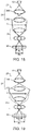
  • FIG. 8 is a diagram for explaining a calculation method of a setting value H 0 .
  • FIG. 9 is a diagram for explaining a calculation method of the setting value H 0 .
  • FIG. 10 is a diagram for explaining a calculation method of the setting value H 0 .
  • FIG. 11 is a flow chart illustrating an example of optimization processing of an incidence angle.
  • FIG. 12 is a diagram for explaining an operation of an optical system during optimization processing of an incidence angle.
  • FIG. 13 is a diagram for explaining an operation of an optical system during optimization processing of an incidence angle.
  • FIG. 14 is a diagram for explaining an operation of an optical system during optimization processing of an incidence angle.
  • FIG. 15 is a diagram for explaining a calculation method of an initial value D 1 and an amount of change ⁇ D.
  • FIG. 16 is a diagram illustrating a configuration of an electron microscope according to a third embodiment.
  • FIG. 17 is a flow chart illustrating an example of optimization processing of an illumination angle.
  • FIG. 18 is a diagram for explaining an operation of an optical system during optimization processing of an illumination angle.
  • FIG. 19 is a diagram for explaining an operation of an optical system during optimization processing of an illumination angle.
  • FIG. 20 is a diagram for explaining an operation of an optical system during optimization processing of an illumination angle.
  • FIG. 21 is a diagram for explaining a calculation method of an initial value I 1 and an amount of change ⁇ I.
  • FIG. 22 is a diagram for explaining a calculation method of a setting value I 0 .
  • FIG. 23 is a diagram for explaining a calculation method of the setting value I 0 .
  • FIG. 24 is a diagram for explaining a calculation method of the setting value I 0 .
  • a charged particle beam device including:
  • control unit which controls the optical system
  • a storage unit which stores previous setting values of the optical system
  • the optical system including:
  • a second optical element for controlling a state of the charged particle beam to be incident on the first optical element
  • control unit performing:
  • control unit obtains the initial value of the setting value of the second optical element based on previous setting values of the second optical element which are stored in the storage unit, an adjustment of the second optical element can be accurately performed in a short period of time.
  • a control method of an optical system of a charged particle beam device which includes: a charged particle source; an optical system which acts on a charged particle beam emitted from the charged particle source; and a storage unit which stores previous setting values of the optical system, the optical system including a first optical element and a second optical element for controlling a state of the charged particle beam to be incident on the first optical element,
  • control method including:
  • the charged particle beam device according to the invention may be an apparatus that performs an observation and an analysis of a specimen by irradiating a charged particle beam (such as an ion beam) other than an electron beam.
  • a charged particle beam device include a transmission electron microscope, a scanning transmission electron microscope, a scanning electron microscope, and a focused ion-beam device.
  • FIG. 1 is a diagram illustrating a configuration of an electron microscope 100 according to the first embodiment.
  • the electron microscope 100 includes an electron source 10 which is an example of the charged particle source, an optical system 20 , a detector 30 , a control unit 40 , and a storage unit 50 .
  • the electron source 10 generates electron beams.
  • the electron source 10 is, for example, an electron gun which accelerates electrons emitted from a cathode by an anode and which emits the accelerated electrons as an electron beam.
  • the optical system 20 acts on an electron beam emitted from the electron source 10 .
  • the optical system 20 includes a multi-stage deflector 22 , an illumination lens system 24 , and an imaging lens system 26 .
  • the illumination lens system 24 is an example of the first optical element and the multi-stage deflector 22 is an example of the second optical element.
  • the multi-stage deflector 22 causes an electron beam emitted from the electron source 10 to be deflected two-dimensionally.
  • the multi-stage deflector 22 is constituted by two deflection coils arranged along an optical axis. It should be noted that, alternatively, the multi-stage deflector 22 may be constituted by three or more deflection coils arranged along the optical axis.
  • the multi-stage deflector 22 is used in order to control a state of an electron beam to be incident on the illumination lens system 24 . Specifically, the multi-stage deflector 22 is used in order to control an incidence position of an electron beam with respect to the illumination lens system 24 and an incidence angle of the electron beam with respect to an optical axis of the illumination lens system 24 .
  • the illumination lens system 24 causes the electron beam emitted from the electron source 10 to converge and illuminates a specimen S with the converged electron beam.
  • the illumination lens system 24 is a multi-stage lens system.
  • the illumination lens system 24 is constituted by two illumination lenses arranged along an optical axis.
  • the illumination lens system 24 is a two-stage lens system.
  • the illumination lens system 24 may be constituted by three or more illumination lenses arranged along the optical axis.
  • the electron microscope 100 is equipped with a specimen stage for holding the specimen S.
  • the specimen S can be positioned by the specimen stage.
  • the imaging lens system 26 forms a transmission electron microscope image (a TEM image) with electrons having been transmitted through the specimen S.
  • the detector 30 photographs a TEM image formed by the imaging lens system 26 .
  • the detector 30 is a digital camera such as a charge coupled device (CCD) camera.
  • CCD charge coupled device
  • the control unit 40 controls the electron source 10 , the optical system 20 , and the detector 30 . As will be described later, the control unit 40 performs: processing of obtaining an initial value of a setting value of the multi-stage deflector 22 ; and processing of changing a state of an electron beam by changing a setting value of the multi-stage deflector 22 from the initial value and obtaining a setting value of the multi-stage deflector 22 based on the change in the state of the electron beam.
  • the state of the electron beam refers to an incidence position of the electron beam with respect to the illumination lens system 24 .
  • the control unit 40 performs processing of controlling the incidence position of the electron beam with respect to the illumination lens system 24 . Details of the processing performed by the control unit 40 will be described later.
  • Functions of the control unit 40 can be realized by, for example, having various processors (a central processing unit (CPU) and the like) execute programs. Alternatively, at least a part of the functions of the control unit 40 may be realized by a dedicated circuit.
  • processors a central processing unit (CPU) and the like
  • the storage unit 50 serves as a work area for the control unit 40 , and functions thereof can be realized by a random access memory (RAM), a read only memory (ROM), a hard disk, or the like.
  • the storage unit 50 stores programs, data, and the like that enable the control unit 40 to perform various control processes and calculation processes. In addition, the storage unit 50 is also used to temporarily store results of calculations and the like performed by the control unit 40 according to various programs.
  • the storage unit 50 stores previous setting values of the optical system 20 .
  • the optical system 20 is controlled by the control unit 40 .
  • the control unit 40 controls the multi-stage deflector 22 so that an incidence position of an electron beam with respect to the illumination lens system 24 assumes an optimal position.
  • this processing will also be referred to as optimization processing of an incidence position.
  • an optimal incidence position is an incidence position where a change in a position of an electron beam having passed through the illumination lens system 24 is minimized even if the setting value of the illumination lens system 24 is changed.
  • FIG. 2 is a flow chart illustrating an example of the optimization processing of an incidence position.
  • FIGS. 3 to 5 are diagrams for explaining an operation of the optical system 20 during the optimization processing of an incidence position. It should be noted that, in FIGS. 3 to 5 , only the electron source 10 , the multi-stage deflector 22 , the illumination lens system 24 , and the specimen S are illustrated for the sake of brevity.
  • the control unit 40 determines whether or not a user has issued an instruction (a start instruction) to start the optimization processing of an incidence position (S 100 ). For example, the control unit 40 determines that the user has issued a start instruction when a press operation of a start button for issuing an instruction to start the optimization processing of an incidence position is performed or when a start instruction is input from an input device or the like.
  • the control unit 40 calculates an initial value H 1 of a setting value Hn of the multi-stage deflector 22 and an amount of change ⁇ H of the setting value Hn of the multi-stage deflector 22 (S 102 ).
  • the setting value Hn of the multi-stage deflector 22 is a value that controls the incidence position of an electron beam with respect to the illumination lens system 24 . A calculation method of the initial value H 1 and the amount of change ⁇ H will be described later.
  • control unit 40 sets the setting value of the multi-stage deflector 22 to the initial value H 1 and obtains a first amount of change ⁇ P 1 which is an amount of change of the position of the electron beam having passed through the illumination lens system 24 when the setting value of the illumination lens system 24 is changed (S 106 to S 116 ).
  • control unit 40 sets the setting value of the multi-stage deflector 22 to the initial value H 1 (S 106 ).
  • the initial value H 1 the value calculated in the processing of step S 102 is used.
  • the control unit 40 sets the setting value of the illumination lens system 24 to a setting value S 1 (S 108 ).
  • the setting value S 1 is, for example, a value that maximizes a beam diameter of the electron beam on the specimen S.
  • the control unit 40 measures a position Pa of the electron beam on the specimen S as illustrated in FIG. 3 (S 110 ). For example, the control unit 40 acquires a TEM image photographed by the detector 30 and measures the position Pa from the acquired TEM image.
  • the control unit 40 sets the setting value of the illumination lens system 24 to a setting value S 2 (S 112 ).
  • the setting value S 2 is, for example, a value that minimizes the beam diameter of the electron beam on the specimen S.
  • the control unit 40 measures a position Pb of the electron beam on the specimen S as illustrated in FIG. 3 (S 114 ). For example, the control unit 40 acquires a TEM image photographed by the detector 30 and measures the position Pb from the acquired TEM image.
  • the control unit 40 sets the setting value of the multi-stage deflector 22 to the setting value H 2 (S 106 ).
  • the setting value H 2 is a value as a result of changing the initial value H 1 by the amount of change ⁇ H obtained in step S 102 .
  • H 2 H 1 + ⁇ H.
  • control unit 40 sets the setting value of the illumination lens system 24 to the setting value S 1 (S 108 ).
  • the control unit 40 measures the position Pa of the electron beam on the specimen S as illustrated in FIG. 4 (S 110 ).
  • control unit 40 sets the setting value of the illumination lens system 24 to the setting value S 2 (S 112 ).
  • the control unit 40 measures the position Pb of the electron beam on the specimen S as illustrated in FIG. 4 (S 114 ).
  • the control unit 40 sets the setting value of the multi-stage deflector 22 to the setting value H 3 (S 106 ).
  • the setting value H 3 is a value as a result of changing the initial value H 1 by the amount of change ⁇ H obtained in step S 102 .
  • H 3 H 1 ⁇ H.
  • control unit 40 sets the setting value of the illumination lens system 24 to the setting value S 1 (S 108 ).
  • the control unit 40 measures the position Pa of the electron beam on the specimen S as illustrated in FIG. 5 (S 110 ).
  • control unit 40 sets the setting value of the illumination lens system 24 to the setting value S 2 (S 112 ).
  • the control unit 40 measures the position Pb of the electron beam on the specimen S as illustrated in FIG. 5 (S 114 ).
  • a calculation method of the setting value H 0 will be described later.
  • the control unit 40 sets the setting value of the multi-stage deflector 22 to the setting value H 0 obtained in step S 122 (S 124 ). Subsequently, the control unit 40 ends the processing.
  • the control unit 40 obtains the initial value H 1 and the amount of change ⁇ H based on previous setting values of the multi-stage deflector 22 which are stored in the storage unit 50 .
  • FIG. 6 is a diagram for explaining the calculation method of the initial value H 1 and the amount of change ⁇ H.
  • An abscissa of a graph in FIG. 6 represents a time point T and an ordinate of the graph represents the setting value H 0 of the multi-stage deflector 22 .
  • the control unit 40 causes the storage unit 50 to store a setting value of the multi-stage deflector 22 at set time intervals.
  • the control unit 40 causes the storage unit 50 to store, together with the setting value, a time point at which the setting value had been stored.
  • the setting value H 0 of the multi-stage deflector 22 is stored in the storage unit 50 at a time interval ⁇ T.
  • the setting values H 0 at a time point T 1 , a time point T 2 , a time point T 3 , a time point T 4 , a time point T 5 , a time point T 6 , and a time point T 7 are stored in the storage unit 50 .
  • the time interval ⁇ T can be arbitrarily set.
  • the time interval ⁇ T may be 24 hours or 168 hours.
  • the control unit 40 reads the setting values H 0 stored in the storage unit 50 , calculates a time average HT of the setting values H 0 , and adopts the calculated time average HT as the initial value H 1 .
  • H 1 HT.
  • the setting value H 0 at a present time point Tnow is estimated from previous setting values H 0 to determine the initial value H 1 .
  • a timing at which the storage unit 50 is caused to store the time point T and the setting value H 0 is not limited thereto.
  • the control unit 40 need not cause the storage unit 50 to store the time point T and the setting value H 0 at constant time intervals.
  • the control unit 40 may cause the storage unit 50 to store the setting value H 0 obtained in the processing.
  • the control unit 40 causes the storage unit 50 to store the setting value H 0 at a timing where the optimization processing of an incidence position is finished.
  • the control unit 40 causes the storage unit 50 to store the setting value H 0 as soon as the optimization processing of an incidence position is finished.
  • control unit 40 may cause the storage unit 50 to store the time point T and the setting value H 0 at the time interval ⁇ T and, after the optimization processing of an incidence position is finished, the control unit 40 may cause the storage unit 50 to store the time point T and the setting value H 0 obtained in the processing.
  • FIGS. 8 to 10 are diagrams for explaining a calculation method of the setting value H 0 .
  • the setting value H 1 , the setting value H 2 , and the setting value H 3 and the first amount of change ⁇ P 1 , the second amount of change ⁇ P 2 , and the third amount of change ⁇ P 3 are in a linear relationship. Therefore, a relational expression is obtained from these values to obtain the setting value H 0 of the multi-stage deflector 22 at which an amount of change ⁇ P of the position of the electron beam having passed through the illumination lens system 24 becomes zero when the setting value of the illumination lens system 24 is changed.
  • a1, a2, b1, and b2 expressed by the following equations are obtained.
  • a 1 ( ⁇ P 2 ⁇ P 1)/( H 2 ⁇ H 1)
  • a 2 ( ⁇ P 3 ⁇ ⁇ P 2)/( H 3 ⁇ H 2)
  • b 1 ( H 2 ⁇ P 1 ⁇ H 1 ⁇ P 2)/( H 2 ⁇ H 1)
  • b 2 ( H 3 ⁇ P 2 ⁇ H 2 ⁇ P 3)/( H 3 ⁇ H 2)
  • the setting value H 0 is obtained by obtaining a relational expression from the three points of the first amount of change ⁇ P 1 , the second amount of change ⁇ P 2 , and the third amount of change ⁇ P 3 in the example described above, for example, the setting value H 0 may be obtained by obtaining a relational expression from two points or the setting value H 0 may be obtained by obtaining a relational expression from four or more points.
  • the electron microscope 100 has the following effects.
  • the control unit 40 performs: processing of obtaining the initial value H 1 of a setting value of the multi-stage deflector 22 ; and processing of changing a state of an electron beam by changing a setting value of the multi-stage deflector 22 from the initial value H 1 and obtaining a setting value of the multi-stage deflector 22 based on the change in the state of the electron beam.
  • the control unit 40 obtains the initial value H 1 based on previous setting values of the multi-stage deflector 22 which are stored in the storage unit 50 .
  • the control unit 40 obtains the initial value H 1 in optimization processing of an incidence position based on previous setting values of the multi-stage deflector 22 , a setting value estimated from previous setting values can be adopted as the initial value H 1 . Therefore, with the electron microscope 100 , an adjustment of the multi-stage deflector 22 can be accurately performed in a short period of time. Furthermore, in the electron microscope 100 , since the control unit 40 performs the optimization processing of an incidence position, an observation and an analysis can be performed at an optimal incidence position of an electron beam without the user having to perform an adjustment. In addition, for example, when the user manually performs an adjustment of the multi-stage deflector 22 , a variation may occur among settings due to the user's skill. By comparison, in the electron microscope 100 , a variation among settings due to the user's skill does not occur.
  • the initial value H 1 is a time average of previous setting values of the multi-stage deflector 22 which are stored in the storage unit 50 . Therefore, with the electron microscope 100 , an adjustment of the multi-stage deflector 22 can be accurately performed in a short period of time.
  • the control unit 40 performs processing of obtaining the amount of change ⁇ H from the initial value H 1 , and in the processing of obtaining a setting value of the multi-stage deflector 22 , the setting value of the multi-stage deflector 22 is changed from the initial value H 1 by the obtained amount of change ⁇ H.
  • the control unit 40 obtains the amount of change ⁇ H based on previous setting values of the multi-stage deflector 22 which are stored in the storage unit 50 .
  • the amount of change ⁇ H is a standard deviation of previous setting values of the multi-stage deflector 22 which are stored in the storage unit 50 .
  • the amount of change ⁇ H can be obtained from a variation in the setting value as predicted from the variation in previous setting values. Therefore, with the electron microscope 100 , an adjustment of the multi-stage deflector 22 can be accurately performed in a short period of time.
  • the control unit 40 causes the storage unit 50 to store a setting value of the multi-stage deflector 22 at set time intervals. As a result, a change over time of the setting value of the multi-stage deflector 22 can be stored. Therefore, with the electron microscope 100 , an adjustment of the multi-stage deflector 22 can be accurately performed in a short period of time.
  • the control unit 40 causes the storage unit 50 to store the obtained setting value of the multi-stage deflector 22 . Therefore, the storage unit 50 can be caused to store a change over time of the setting value of the multi-stage deflector 22 . In addition, the storage unit 50 can be caused to store a setting value in a state where an incidence position of an electron beam has been further optimized.
  • a configuration of the electron microscope according to the second embodiment is the same as the configuration of the electron microscope 100 according to the first embodiment illustrated in FIG. 1 and, therefore, a description thereof will be omitted.
  • a setting value of the multi-stage deflector 22 is a value that controls an incidence position of an electron beam with respect to the illumination lens system 24 and the control unit 40 controls the multi-stage deflector 22 so that the incidence position of the electron beam with respect to the illumination lens system 24 assumes an optimal position.
  • a setting value of the multi-stage deflector 22 is a value that controls an incidence angle of an electron beam with respect to an optical axis of the illumination lens system 24 and the control unit 40 performs processing of controlling the multi-stage deflector 22 so that the incidence angle of the electron beam with respect to the illumination lens system 24 assumes an optimal incidence angle.
  • this processing will also be referred to as optimization processing of an incidence angle.
  • an optimal incidence angle is an incidence angle where a change in a position of an electron beam having passed through the illumination lens system 24 is minimized even if the setting value of the illumination lens system 24 is changed.
  • FIG. 11 is a flow chart illustrating an example of the optimization processing of an incidence angle.
  • FIGS. 12 to 14 are diagrams for explaining an operation of the optical system 20 during the optimization processing of an incidence angle. It should be noted that, in FIGS. 12 to 14 , only the electron source 10 , the multi-stage deflector 22 , the illumination lens system 24 , and the specimen S are illustrated for the sake of brevity.
  • the control unit 40 determines whether or not the user has issued an instruction to start optimization processing of an incidence angle (S 200 ).
  • the control unit 40 calculates an initial value D 1 of a setting value Dn of the multi-stage deflector 22 and an amount of change ⁇ D of the setting value Dn of the multi-stage deflector 22 (S 202 ).
  • the setting value Dn of the multi-stage deflector 22 is a value that controls the incidence angle of the electron beam with respect to an optical axis of the illumination lens system 24 . A calculation method of the initial value D 1 and the amount of change ⁇ D will be described later.
  • control unit 40 sets the setting value of the multi-stage deflector 22 to the initial value D 1 and obtains the first amount of change ⁇ P 1 which is an amount of change of the position of the electron beam having passed through the illumination lens system 24 when the setting value of the illumination lens system 24 is changed (S 206 to S 216 ).
  • control unit 40 sets the setting value of the multi-stage deflector 22 to the initial value D 1 (S 206 ).
  • the initial value D 1 the value calculated in the processing of step S 202 is used.
  • control unit 40 sets the setting value of the illumination lens system 24 to the setting value S 1 (S 208 ).
  • the control unit 40 measures the position Pa of the electron beam on the specimen S as illustrated in FIG. 12 (S 210 ).
  • control unit 40 sets the setting value of the illumination lens system 24 to the setting value S 2 (S 212 ).
  • the control unit 40 measures the position Pb of the electron beam on the specimen S as illustrated in FIG. 12 (S 214 ).
  • the control unit 40 sets the setting value of the multi-stage deflector 22 to the setting value D 2 (S 206 ).
  • the setting value D 2 is a value as a result of changing the initial value D 1 by the amount of change ⁇ D obtained in step S 202 .
  • D 2 D 1 + ⁇ D.
  • control unit 40 sets the setting value of the illumination lens system 24 to the setting value S 1 (S 208 ).
  • the control unit 40 measures the position Pa of the electron beam on the specimen S as illustrated in FIG. 13 (S 210 ).
  • control unit 40 sets the setting value of the illumination lens system 24 to the setting value S 2 (S 212 ).
  • the control unit 40 measures the position Pb of the electron beam on the specimen S as illustrated in FIG. 13 (S 214 ).
  • the control unit 40 sets the setting value of the multi-stage deflector 22 to the setting value D 3 (S 206 ).
  • the setting value D 3 is a value as a result of changing the initial value D 1 by the amount of change ⁇ D obtained in step S 202 .
  • D 3 D 1 + ⁇ D.
  • control unit 40 sets the setting value of the illumination lens system 24 to the setting value S 1 (S 208 ).
  • the control unit 40 measures the position Pa of the electron beam on the specimen S as illustrated in FIG. 14 (S 210 ).
  • control unit 40 sets the setting value of the illumination lens system 24 to the setting value S 2 (S 212 ).
  • the control unit 40 measures the position Pb of the electron beam on the specimen S as illustrated in FIG. 14 (S 214 ).
  • a calculation method of the setting value D 0 will be described later.
  • the control unit 40 sets the setting value of the multi-stage deflector 22 to the setting value D 0 determined in step S 222 (S 224 ). Subsequently, the control unit 40 ends the processing.
  • FIG. 15 is a diagram for explaining the calculation method of the initial value D 1 and the amount of change ⁇ D.
  • the calculation method of the initial value D 1 and the amount of change ⁇ D is similar to the calculation method of the initial value H 1 and the amount of change ⁇ H described above. Specifically, the control unit 40 obtains the initial value D 1 and the amount of change ⁇ D based on previous setting values of the multi-stage deflector 22 which are stored in the storage unit 50 .
  • control unit 40 causes the storage unit 50 to store the setting value D 0 of the multi-stage deflector 22 at set time intervals as illustrated in FIG. 15 .
  • control unit 40 causes the storage unit 50 to store, together with the setting value D 0 , a time point at which the setting value D 0 had been stored.
  • the control unit 40 reads the setting values D 0 stored in the storage unit 50 , calculates a time average DT of the setting values D 0 , and adopts the calculated time average DT as the initial value D 1 .
  • D 1 DT.
  • the setting value D 0 at a present time point Tnow is estimated from previous setting values D 0 to determine the initial value D 1 .
  • the calculation method of the setting value D 0 is similar to the calculation method of the setting value H 0 described above. Specifically, taking advantage of the fact that the setting value D 1 , the setting value D 2 , and the setting value D 3 and the first amount of change ⁇ P 1 , the second amount of change ⁇ P 2 , and the third amount of change ⁇ P 3 are in a linear relationship, a relational expression is obtained from these values. In addition, from the relational expression, the setting value D 0 of the multi-stage deflector 22 is obtained at which the amount of change ⁇ P becomes zero when the setting value of the illumination lens system 24 is changed.
  • a1, a2, b1, and b2 expressed by the following equations are obtained.
  • a 1 ( ⁇ P 2 ⁇ P 1)/( D 2 ⁇ D 1)
  • a 2 ( ⁇ P 3 ⁇ P 2)/( D 3 ⁇ D 2)
  • b 1 ( D 2 ⁇ P 1 ⁇ D 1 ⁇ P 2)/( D 2 ⁇ D 1)
  • b 2 ( D 3 ⁇ P 2 ⁇ D 2 ⁇ P 3)/( D 3 ⁇ D 2)
  • the electron microscope 100 according to the second embodiment has the following effects.
  • control unit 40 obtains the initial value D 1 and the amount of change ⁇ D in the optimization processing of an incidence angle based on previous setting values of the multi-stage deflector 22 , an adjustment of the multi-stage deflector 22 can be accurately performed within a short period of time.
  • FIG. 16 is a diagram illustrating a configuration of an electron microscope 300 according to the third embodiment.
  • members having similar functions to the components of the electron microscope 100 according to the first embodiment will be denoted by same reference characters and a detailed description thereof will be omitted.
  • the illumination lens system 24 has a dose adjustment lens 240 and an illumination lens 242 . It should be noted that the illumination lens 242 is an example of the first optical element and the dose adjustment lens 240 is an example of the second optical element.
  • the dose adjustment lens 240 is a lens for controlling a dose of an electron beam with respect to the specimen S by controlling an illumination angle of the electron beam or, in other words, a divergence angle of the electron beam.
  • the illumination lens 242 is a lens for illuminating the specimen S with the electron beam.
  • the illumination lens 242 is arranged to the rear of the dose adjustment lens 240 .
  • the illumination lens 242 is arranged directly above the specimen S.
  • the dose adjustment lens 240 is used to parallelly illuminate the specimen S with the electron beam.
  • Koehler illumination can be realized by the dose adjustment lens 240 .
  • the optical system 20 is controlled by the control unit 40 .
  • the control unit 40 controls the dose adjustment lens 240 so that an illumination angle of an electron beam which illuminates the specimen S assumes an optimal angle.
  • this processing will also be referred to as optimization processing of an illumination angle.
  • the optimal illumination angle can be set to an arbitrary angle.
  • the dose adjustment lens 240 is adjusted so that an electron beam parallelly illuminates the specimen S.
  • FIG. 17 is a flow chart illustrating an example of the optimization processing of an illumination angle.
  • FIGS. 18 to 20 are diagrams for explaining an operation of the optical system 20 during the optimization processing of an illumination angle. It should be noted that, in FIGS. 18 to 20 , only the electron source 10 , the dose adjustment lens 240 , the illumination lens 242 , the imaging lens system 26 , and the detector 30 are illustrated for the sake of brevity.
  • the control unit 40 determines whether or not the user has issued an instruction to start the optimization processing of an illumination angle (S 300 ).
  • the control unit 40 calculates an initial value I 1 of a setting value In of the dose adjustment lens 240 and an amount of change ⁇ I of the setting value In of the dose adjustment lens 240 (S 302 ).
  • the setting value In of the dose adjustment lens 240 is a value that controls an illumination angle of an electron beam. A calculation method of the initial value I 1 and the amount of change ⁇ I will be described later.
  • control unit 40 sets the setting value of the dose adjustment lens 240 to the initial value I 1 and obtains a first amount of change ⁇ R 1 which is an amount of change of a beam diameter of the electron beam having passed through the illumination lens 242 when the setting value of the illumination lens 242 is changed (S 306 to S 316 ).
  • the control unit 40 sets the setting value of the dose adjustment lens 240 to the initial value I 1 (S 306 ).
  • the initial value I 1 the value calculated in the processing of step S 302 is used.
  • the control unit 40 sets the setting value of the illumination lens 242 to a setting value O 1 (S 308 ).
  • the setting value O 1 can be set to an arbitrary value.
  • the control unit 40 measures a beam diameter Ra of the electron beam on the detector 30 as illustrated in FIG. 18 (S 310 ). For example, the control unit 40 acquires a TEM image photographed by the detector 30 and measures the beam diameter Ra from the acquired TEM image.
  • the control unit 40 sets the setting value of the illumination lens 242 to a setting value O 2 (S 312 ).
  • the amount of change ⁇ O can be set to an arbitrary value.
  • the setting value O 2 is set to a value that differs from the setting value O 1 .
  • the control unit 40 measures a beam diameter Rb of the electron beam on the detector 30 as illustrated in FIG. 18 (S 314 ). For example, the control unit 40 acquires a TEM image photographed by the detector 30 and measures the beam diameter Rb from the acquired TEM image.
  • control unit 40 sets the setting value of the dose adjustment lens 240 to a setting value I 2 which represents a change by the amount of change ⁇ I from the initial value I 1 and obtains a second amount of change ⁇ R 2 which is an amount of change of the beam diameter of the electron beam having passed through the illumination lens 242 when the setting value of the illumination lens 242 is changed (S 306 to S 316 ).
  • the control unit 40 sets the setting value of the dose adjustment lens 240 to the setting value I 2 (S 306 ).
  • the setting value I 2 is a value as a result of changing the initial value I 1 by the amount of change ⁇ I obtained in step S 302 .
  • I 2 I 1 + ⁇ I.
  • the control unit 40 sets the setting value of the illumination lens 242 to the setting value O 1 (S 308 ).
  • the control unit 40 measures the beam diameter Ra of the electron beam on the detector 30 as illustrated in FIG. 19 (S 310 ).
  • the control unit 40 sets the setting value of the illumination lens 242 to the setting value O 2 (S 312 ).
  • the control unit 40 measures the beam diameter Rb of the electron beam on the detector 30 as illustrated in FIG. 19 (S 314 ).
  • control unit 40 sets the setting value of the dose adjustment lens 240 to a setting value I 3 which represents a change by an amount of change ⁇ I from the initial value I 1 and obtains a third amount of change ⁇ R 3 which is an amount of change of the beam diameter of the electron beam having passed through the illumination lens 242 when the setting value of the illumination lens 242 is changed (S 306 to S 316 ).
  • the control unit 40 sets the setting value of the dose adjustment lens 240 to the setting value I 3 (S 306 ).
  • the setting value I 3 is a value as a result of changing the initial value I 1 by the amount of change ⁇ I obtained in step S 302 .
  • I 3 I 1 ⁇ I.
  • the control unit 40 sets the setting value of the illumination lens 242 to the setting value O 1 (S 308 ).
  • the control unit 40 measures the beam diameter Ra of the electron beam on the detector 30 as illustrated in FIG. 20 (S 310 ).
  • the control unit 40 sets the setting value of the illumination lens 242 to the setting value O 2 (S 312 ).
  • the control unit 40 measures the beam diameter Rb of the electron beam on the detector 30 as illustrated in FIG. 20 (S 314 ).
  • a calculation method of the setting value I 0 will be described later.
  • the control unit 40 sets the setting value of the dose adjustment lens 240 to the setting value I 0 determined in step S 322 (S 324 ). Subsequently, the control unit 40 ends the processing.
  • FIG. 21 is a diagram for explaining the calculation method of the initial value I 1 and the amount of change ⁇ I.
  • the calculation method of the initial value I 1 and the amount of change ⁇ I is similar to the calculation method of the initial value H 1 and the amount of change ⁇ H described above. Specifically, the control unit 40 obtains the initial value I 1 and the amount of change ⁇ I based on previous setting values of the dose adjustment lens 240 which are stored in the storage unit 50 .
  • the control unit 40 causes the storage unit 50 to store a setting value of the dose adjustment lens 240 at set time intervals. In addition, the control unit 40 causes the storage unit 50 to store, together with the setting value I 0 , a time point at which the setting value I 0 had been stored.
  • the control unit 40 reads the setting values I 0 stored in the storage unit 50 , calculates a time average IT of the setting value I 0 , and adopts the calculated time average IT as the initial value I 1 .
  • I 1 IT.
  • step S 322 a calculation method of the setting value I 0 in step S 322 will be described.
  • FIGS. 22 to 24 are diagrams for explaining a calculation method of the setting value I 0 .
  • the setting value I 1 , the setting value I 2 , and the setting value I 3 and the first amount of change ⁇ R 1 , the second amount of change ⁇ R 2 , and the third amount of change ⁇ R 3 are in a linear relationship. Therefore, a relational expression is obtained from these values to obtain the setting value I 0 of the dose adjustment lens 240 at which the amount of change ⁇ R of the beam diameter of an electron beam having passed through the illumination lens 242 becomes zero when the setting value of the illumination lens 242 is changed.
  • a1, a2, b1, and b2 expressed by the following equations are obtained.
  • a 1 ( ⁇ R 2 ⁇ R 1)/( I 2 ⁇ I 1)
  • a 2 ( ⁇ R 3 ⁇ R 2)/( I 3 ⁇ I 2)
  • b 1 ( I 2 ⁇ R 1 ⁇ I 1 ⁇ R 2)/( I 2 ⁇ I 1)
  • b 2 ( I 3 ⁇ R 2 ⁇ I 2 ⁇ R 3)/( I 3 ⁇ I 2)
  • the calculation method of the setting value I 0 is not limited to the example described above.
  • the electron microscope 300 has the following effects.
  • the control unit 40 obtains the initial value I 1 and the amount of change ⁇ I in the optimization processing of an illumination angle based on previous setting values of the dose adjustment lens 240 , an adjustment of the dose adjustment lens 240 can be accurately performed within a short period of time.
  • the illumination angle can also be set to an arbitrary angle in the optimization processing of an illumination angle.
  • the setting value I 1 , the setting value I 2 , and the setting value I 3 and the first amount of change ⁇ R 1 , the second amount of change ⁇ R 2 , and the third amount of change ⁇ R 3 are in a linear relationship. Therefore by obtaining a relationship between the amount of change ⁇ R and the illumination angle in advance, the dose adjustment lens 240 can also be adjusted so as to realize a desired illumination angle in the optimization processing of an illumination angle.
  • the invention includes configurations that are substantially the same (for example, in function, method, and results, or in objective and effects) as the configurations described in the embodiments.
  • the invention also includes configurations in which non-essential elements described in the embodiments are replaced by other elements.
  • the invention also includes configurations having the same effects as those of the configurations described in the embodiments, or configurations capable of achieving the same objectives as those of the configurations described in the embodiments.
  • the invention further includes configurations obtained by adding known art to the configurations described in the embodiments.

Landscapes

  • Chemical & Material Sciences (AREA)
  • Analytical Chemistry (AREA)
  • Electron Sources, Ion Sources (AREA)

Abstract

A charged particle beam device includes: a charged particle source; an optical system which acts on a charged particle beam emitted from the charged particle source; a control unit which controls the optical system; and a storage unit which stores previous setting values of the optical system. The optical system includes a first optical element and a second optical element for controlling a state of the charged particle beam to be incident on the first optical element. The control unit obtains an initial value of a setting value of the second optical element based on previous setting values of the second optical element; and changes a state of the charged particle beam by changing the setting value of the second optical element from the obtained initial value and obtains the setting value of the second optical element based on the change in the state of the charged particle beam.

Description

CROSS-REFERENCE TO RELATED APPLICATION
This application claims priority to Japanese Patent Application No. 2019-084296 filed Apr. 25, 2019, the disclosure of which is hereby incorporated by reference in its entirety.
BACKGROUND OF THE INVENTION Field of the Invention
The present invention relates to a charged particle beam device and to a control method of an optical system of a charged particle beam device.
Description of Related Art
In charged particle beam devices such as a transmission electron microscope and a scanning electron microscope, adjustment of an optical system is performed prior to performing observation and analysis. For example, adjustment of a deflector which controls a position and an angle of an electron beam is performed so that the electron beam is incident along an optical axis of a probe-forming lens. In addition, for example, with a transmission electron microscope, adjustment of a lens that controls an illumination angle of an electron beam is performed so that the electron beam is incident in parallel to a specimen.
For example, JP-A-2017-10608 discloses, as a method of correcting a minute tilt angle of a charged particle beam, arranging a reflector between a charged particle source and an objective lens and performing tilt correction of the charged particle beam based on information related to a scanned image created by emitted charged particles which are emitted from a specimen and obtained by the reflector.
Such adjustments of an optical system are preferably performed accurately within a short period of time.
SUMMARY OF THE INVENTION
According to a first aspect of the invention, there is provided a charged particle beam device including:
a charged particle source;
an optical system which acts on a charged particle beam emitted from the charged particle source;
a control unit which controls the optical system; and
a storage unit which stores previous setting values of the optical system,
the optical system including:
a first optical element; and
a second optical element for controlling a state of the charged particle beam to be incident on the first optical element,
the control unit performing:
processing of obtaining an initial value of a setting value of the second optical element based on previous setting values of the second optical element which are stored in the storage unit; and
processing of changing a state of the charged particle beam by changing the setting value of the second optical element from the obtained initial value and obtaining the setting value of the second optical element based on the change in the state of the charged particle beam.
According to a second aspect of the invention, there is provided a control method of an optical system of a charged particle beam device which includes: a charged particle source; an optical system which acts on a charged particle beam emitted from the charged particle source; and a storage unit which stores previous setting values of the optical system, the optical system including a first optical element and a second optical element for controlling a state of the charged particle beam to be incident on the first optical element,
the control method including:
obtaining an initial value of a setting value of the second optical element based on previous setting values of the second optical element which are stored in the storage unit; and
changing a state of the charged particle beam by changing the setting value of the second optical element from the obtained initial value and obtaining the setting value of the second optical element based on the change in the state of the charged particle beam.
BRIEF DESCRIPTION OF THE DRAWINGS
FIG. 1 is a diagram illustrating a configuration of an electron microscope according to a first embodiment.
FIG. 2 is a flow chart illustrating an example of optimization processing of an incidence position.
FIG. 3 is a diagram for explaining an operation of an optical system during optimization processing of an incidence position.
FIG. 4 is a diagram for explaining an operation of an optical system during optimization processing of an incidence position.
FIG. 5 is a diagram for explaining an operation of an optical system during optimization processing of an incidence position.
FIG. 6 is a diagram for explaining a calculation method of an initial value H1 and an amount of change ΔH.
FIG. 7 is a diagram for explaining a calculation method of the initial value H1 and the amount of change ΔH.
FIG. 8 is a diagram for explaining a calculation method of a setting value H0.
FIG. 9 is a diagram for explaining a calculation method of the setting value H0.
FIG. 10 is a diagram for explaining a calculation method of the setting value H0.
FIG. 11 is a flow chart illustrating an example of optimization processing of an incidence angle.
FIG. 12 is a diagram for explaining an operation of an optical system during optimization processing of an incidence angle.
FIG. 13 is a diagram for explaining an operation of an optical system during optimization processing of an incidence angle.
FIG. 14 is a diagram for explaining an operation of an optical system during optimization processing of an incidence angle.
FIG. 15 is a diagram for explaining a calculation method of an initial value D1 and an amount of change ΔD.
FIG. 16 is a diagram illustrating a configuration of an electron microscope according to a third embodiment.
FIG. 17 is a flow chart illustrating an example of optimization processing of an illumination angle.
FIG. 18 is a diagram for explaining an operation of an optical system during optimization processing of an illumination angle.
FIG. 19 is a diagram for explaining an operation of an optical system during optimization processing of an illumination angle.
FIG. 20 is a diagram for explaining an operation of an optical system during optimization processing of an illumination angle.
FIG. 21 is a diagram for explaining a calculation method of an initial value I1 and an amount of change ΔI.
FIG. 22 is a diagram for explaining a calculation method of a setting value I0.
FIG. 23 is a diagram for explaining a calculation method of the setting value I0.
FIG. 24 is a diagram for explaining a calculation method of the setting value I0.
DESCRIPTION OF THE INVENTION
(1) According to an embodiment of the invention, there is provided a charged particle beam device including:
a charged particle source;
an optical system which acts on a charged particle beam emitted from the charged particle source;
a control unit which controls the optical system; and
a storage unit which stores previous setting values of the optical system,
the optical system including:
a first optical element; and
a second optical element for controlling a state of the charged particle beam to be incident on the first optical element,
the control unit performing:
processing of obtaining an initial value of a setting value of the second optical element based on previous setting values of the second optical element which are stored in the storage unit; and
processing of changing a state of the charged particle beam by changing the setting value of the second optical element from the obtained initial value and obtaining the setting value of the second optical element based on the change in the state of the charged particle beam.
With such a charged particle beam device, since the control unit obtains the initial value of the setting value of the second optical element based on previous setting values of the second optical element which are stored in the storage unit, an adjustment of the second optical element can be accurately performed in a short period of time.
(2) According to an embodiment of the invention, there is provided a control method of an optical system of a charged particle beam device which includes: a charged particle source; an optical system which acts on a charged particle beam emitted from the charged particle source; and a storage unit which stores previous setting values of the optical system, the optical system including a first optical element and a second optical element for controlling a state of the charged particle beam to be incident on the first optical element,
the control method including:
obtaining an initial value of a setting value of the second optical element based on previous setting values of the second optical element which are stored in the storage unit; and
changing a state of the charged particle beam by changing the setting value of the second optical element from the obtained initial value and obtaining the setting value of the second optical element based on the change in the state of the charged particle beam.
With such a control method of an optical system of a charged particle beam device, since the initial value of the setting value of the second optical element is obtained based on previous setting values of the second optical element which are stored in the storage unit, an adjustment of the second optical element can be accurately performed in a short period of time.
Preferred embodiments of the invention are described in detail below with reference to the drawings. Note that the following embodiments do not unduly limit the scope of the invention as stated in the claims. In addition, all of the elements described below are not necessarily essential requirements of the invention.
Furthermore, while the charged particle beam device according to the invention will be described below using an electron microscope that performs an observation and an analysis of a specimen by illuminating the specimen with an electron beam as an example, the charged particle beam device according to the invention may be an apparatus that performs an observation and an analysis of a specimen by irradiating a charged particle beam (such as an ion beam) other than an electron beam. Examples of such a charged particle beam device include a transmission electron microscope, a scanning transmission electron microscope, a scanning electron microscope, and a focused ion-beam device.
1. First Embodiment 1.1. Configuration of Electron Microscope
First, an electron microscope according to a first embodiment will be described with reference to the drawings. FIG. 1 is a diagram illustrating a configuration of an electron microscope 100 according to the first embodiment.
As illustrated in FIG. 1, the electron microscope 100 includes an electron source 10 which is an example of the charged particle source, an optical system 20, a detector 30, a control unit 40, and a storage unit 50.
The electron source 10 generates electron beams. The electron source 10 is, for example, an electron gun which accelerates electrons emitted from a cathode by an anode and which emits the accelerated electrons as an electron beam.
The optical system 20 acts on an electron beam emitted from the electron source 10. The optical system 20 includes a multi-stage deflector 22, an illumination lens system 24, and an imaging lens system 26. It should be noted that the illumination lens system 24 is an example of the first optical element and the multi-stage deflector 22 is an example of the second optical element.
The multi-stage deflector 22 causes an electron beam emitted from the electron source 10 to be deflected two-dimensionally. In the illustrated example, the multi-stage deflector 22 is constituted by two deflection coils arranged along an optical axis. It should be noted that, alternatively, the multi-stage deflector 22 may be constituted by three or more deflection coils arranged along the optical axis.
The multi-stage deflector 22 is used in order to control a state of an electron beam to be incident on the illumination lens system 24. Specifically, the multi-stage deflector 22 is used in order to control an incidence position of an electron beam with respect to the illumination lens system 24 and an incidence angle of the electron beam with respect to an optical axis of the illumination lens system 24.
The illumination lens system 24 causes the electron beam emitted from the electron source 10 to converge and illuminates a specimen S with the converged electron beam. The illumination lens system 24 is a multi-stage lens system. In the illustrated example, the illumination lens system 24 is constituted by two illumination lenses arranged along an optical axis. In other words, the illumination lens system 24 is a two-stage lens system. It should be noted that, alternatively, the illumination lens system 24 may be constituted by three or more illumination lenses arranged along the optical axis.
Although not illustrated, the electron microscope 100 is equipped with a specimen stage for holding the specimen S. The specimen S can be positioned by the specimen stage.
The imaging lens system 26 forms a transmission electron microscope image (a TEM image) with electrons having been transmitted through the specimen S. The detector 30 photographs a TEM image formed by the imaging lens system 26. For example, the detector 30 is a digital camera such as a charge coupled device (CCD) camera. The TEM image photographed by the detector 30 is sent to the control unit 40 and stored in the storage unit 50.
The control unit 40 controls the electron source 10, the optical system 20, and the detector 30. As will be described later, the control unit 40 performs: processing of obtaining an initial value of a setting value of the multi-stage deflector 22; and processing of changing a state of an electron beam by changing a setting value of the multi-stage deflector 22 from the initial value and obtaining a setting value of the multi-stage deflector 22 based on the change in the state of the electron beam. In the first embodiment, the state of the electron beam refers to an incidence position of the electron beam with respect to the illumination lens system 24. In other words, the control unit 40 performs processing of controlling the incidence position of the electron beam with respect to the illumination lens system 24. Details of the processing performed by the control unit 40 will be described later.
Functions of the control unit 40 can be realized by, for example, having various processors (a central processing unit (CPU) and the like) execute programs. Alternatively, at least a part of the functions of the control unit 40 may be realized by a dedicated circuit.
The storage unit 50 serves as a work area for the control unit 40, and functions thereof can be realized by a random access memory (RAM), a read only memory (ROM), a hard disk, or the like. The storage unit 50 stores programs, data, and the like that enable the control unit 40 to perform various control processes and calculation processes. In addition, the storage unit 50 is also used to temporarily store results of calculations and the like performed by the control unit 40 according to various programs. The storage unit 50 stores previous setting values of the optical system 20.
1.2. Control Method of Optical System
Next, a control method of the optical system of the electron microscope 100 according to the first embodiment will be described.
1.2.1. Optimization Processing of Incidence Position
In the electron microscope 100, the optical system 20 is controlled by the control unit 40. Hereinafter, processing will be described in which the control unit 40 controls the multi-stage deflector 22 so that an incidence position of an electron beam with respect to the illumination lens system 24 assumes an optimal position. Hereinafter, this processing will also be referred to as optimization processing of an incidence position.
When an electron beam is incident on a center of the illumination lens system 24 along an optical axis, a position of the electron beam having passed through the illumination lens system 24 does not change even if a setting value of the illumination lens system 24 is changed. Therefore, an optimal incidence position is an incidence position where a change in a position of an electron beam having passed through the illumination lens system 24 is minimized even if the setting value of the illumination lens system 24 is changed.
FIG. 2 is a flow chart illustrating an example of the optimization processing of an incidence position. FIGS. 3 to 5 are diagrams for explaining an operation of the optical system 20 during the optimization processing of an incidence position. It should be noted that, in FIGS. 3 to 5, only the electron source 10, the multi-stage deflector 22, the illumination lens system 24, and the specimen S are illustrated for the sake of brevity.
The control unit 40 determines whether or not a user has issued an instruction (a start instruction) to start the optimization processing of an incidence position (S100). For example, the control unit 40 determines that the user has issued a start instruction when a press operation of a start button for issuing an instruction to start the optimization processing of an incidence position is performed or when a start instruction is input from an input device or the like.
When it is determined that the start instruction has been issued (Yes in S100), the control unit 40 calculates an initial value H1 of a setting value Hn of the multi-stage deflector 22 and an amount of change ΔH of the setting value Hn of the multi-stage deflector 22 (S102). The setting value Hn of the multi-stage deflector 22 is a value that controls the incidence position of an electron beam with respect to the illumination lens system 24. A calculation method of the initial value H1 and the amount of change ΔH will be described later.
Next, the control unit 40 sets the setting value of the multi-stage deflector 22 to the initial value H1 and obtains a first amount of change ΔP1 which is an amount of change of the position of the electron beam having passed through the illumination lens system 24 when the setting value of the illumination lens system 24 is changed (S106 to S116).
Specifically, first, assuming that n=1 is true (S104), the control unit 40 sets the setting value of the multi-stage deflector 22 to the initial value H1 (S106). As the initial value H1, the value calculated in the processing of step S102 is used.
Next, the control unit 40 sets the setting value of the illumination lens system 24 to a setting value S1 (S108). The setting value S1 is, for example, a value that maximizes a beam diameter of the electron beam on the specimen S. In a state where the setting value of the multi-stage deflector 22 is set to the initial value H1 and the setting value of the illumination lens system 24 is set to the setting value S1, the control unit 40 measures a position Pa of the electron beam on the specimen S as illustrated in FIG. 3 (S110). For example, the control unit 40 acquires a TEM image photographed by the detector 30 and measures the position Pa from the acquired TEM image.
Next, the control unit 40 sets the setting value of the illumination lens system 24 to a setting value S2 (S112). The setting value S2 is expressed as S2=S1+ΔS. The setting value S2 is, for example, a value that minimizes the beam diameter of the electron beam on the specimen S. In a state where the setting value of the multi-stage deflector 22 is set to the initial value H1 and the setting value of the illumination lens system 24 is set to the setting value S2, the control unit 40 measures a position Pb of the electron beam on the specimen S as illustrated in FIG. 3 (S114). For example, the control unit 40 acquires a TEM image photographed by the detector 30 and measures the position Pb from the acquired TEM image.
Next, the control unit 40 calculates the first amount of change ΔP1=Pb−Pa (S116). According to the steps described above, the first amount of change ΔP1 can be obtained.
Next, the control unit 40 determines whether or not n=3 is true (S118), and when it is determined that n=3 is false (No in S118), the control unit 40 assumes that n=n+1 is true (S120) and returns to step S106. Subsequently, the control unit 40 sets the setting value of the multi-stage deflector 22 to a setting value H2 which represents a change by the amount of change ΔH from the initial value H1 and obtains a second amount of change ΔP2 which is an amount of change of the position of the electron beam having passed through the illumination lens system 24 when the setting value of the illumination lens system 24 is changed (S106 to S116).
Specifically, first, the control unit 40 sets the setting value of the multi-stage deflector 22 to the setting value H2 (S106). The setting value H2 is a value as a result of changing the initial value H1 by the amount of change ΔH obtained in step S102. For example, H2=H1+ΔH. By having the control unit 40 change the setting value of the multi-stage deflector 22 from the setting value H1 to the setting value H2, the incidence position of the electron beam with respect to the illumination lens system 24 changes.
Next, the control unit 40 sets the setting value of the illumination lens system 24 to the setting value S1 (S108). In a state where the setting value of the multi-stage deflector 22 is set to the setting value H2 and the setting value of the illumination lens system 24 is set to the setting value S1, the control unit 40 measures the position Pa of the electron beam on the specimen S as illustrated in FIG. 4 (S110).
Next, the control unit 40 sets the setting value of the illumination lens system 24 to the setting value S2 (S112). In a state where the setting value of the multi-stage deflector 22 is set to the setting value H2 and the setting value of the illumination lens system 24 is set to the setting value S2, the control unit 40 measures the position Pb of the electron beam on the specimen S as illustrated in FIG. 4 (S114).
Next, the control unit 40 calculates the second amount of change ΔP2=Pb−Pa (S116). According to the steps described above, the second amount of change ΔP2 can be obtained.
Next, the control unit 40 determines whether or not n=3 is true (S118), and when it is determined that n=3 is false (No in S118), the control unit 40 assumes that n=n+1 is true (S120) and returns to step S106. Subsequently, the control unit 40 sets the setting value of the multi-stage deflector 22 to a setting value H3 which represents a change by the amount of change ΔH from the initial value H1 and obtains a third amount of change ΔP3 which is an amount of change of the position of the electron beam having passed through the illumination lens system 24 when the setting value of the illumination lens system 24 is changed (S106 to S116).
Specifically, first, the control unit 40 sets the setting value of the multi-stage deflector 22 to the setting value H3 (S106). The setting value H3 is a value as a result of changing the initial value H1 by the amount of change ΔH obtained in step S102. For example, H3=H1−ΔH. By having the control unit 40 change the setting value of the multi-stage deflector 22 from the setting value H2 to the setting value H3, the incidence position of the electron beam with respect to the illumination lens system 24 changes.
Next, the control unit 40 sets the setting value of the illumination lens system 24 to the setting value S1 (S108). In a state where the setting value of the multi-stage deflector 22 is set to the setting value H3 and the setting value of the illumination lens system 24 is set to the setting value S1, the control unit 40 measures the position Pa of the electron beam on the specimen S as illustrated in FIG. 5 (S110).
Next, the control unit 40 sets the setting value of the illumination lens system 24 to the setting value S2 (S112). In a state where the setting value of the multi-stage deflector 22 is set to the setting value H3 and the setting value of the illumination lens system 24 is set to the setting value S2, the control unit 40 measures the position Pb of the electron beam on the specimen S as illustrated in FIG. 5 (S114).
Next, the control unit 40 calculates the third amount of change ΔP3=Pb−Pa (S116). According to the steps described above, the third amount of change ΔP3 can be obtained.
The control unit 40 determines whether or not n=3 is true (S118), and when it is determined that n=3 is true (Yes in S118), the control unit 40 obtains a setting value H0 of the multi-stage deflector 22 at which an amount of change of the position of the electron beam having passed through the illumination lens system 24 becomes zero when the setting value of the illumination lens system 24 is changed based on the first amount of change ΔP1, the second amount of change ΔP2, and the third amount of change ΔP3 (S122). A calculation method of the setting value H0 will be described later.
The control unit 40 sets the setting value of the multi-stage deflector 22 to the setting value H0 obtained in step S122 (S124). Subsequently, the control unit 40 ends the processing.
1.2.2. Calculation of Initial Value H1 and Amount of Change ΔH
Next, a calculation method of the initial value H1 and the amount of change ΔH in step S102 will be described.
The control unit 40 obtains the initial value H1 and the amount of change ΔH based on previous setting values of the multi-stage deflector 22 which are stored in the storage unit 50. FIG. 6 is a diagram for explaining the calculation method of the initial value H1 and the amount of change ΔH. An abscissa of a graph in FIG. 6 represents a time point T and an ordinate of the graph represents the setting value H0 of the multi-stage deflector 22.
The control unit 40 causes the storage unit 50 to store a setting value of the multi-stage deflector 22 at set time intervals. In addition, the control unit 40 causes the storage unit 50 to store, together with the setting value, a time point at which the setting value had been stored. In the example in FIG. 6, the setting value H0 of the multi-stage deflector 22 is stored in the storage unit 50 at a time interval ΔT. Specifically, the setting values H0 at a time point T1, a time point T2, a time point T3, a time point T4, a time point T5, a time point T6, and a time point T7 are stored in the storage unit 50. The time interval ΔT can be arbitrarily set. For example, the time interval ΔT may be 24 hours or 168 hours.
For example, the control unit 40 reads the setting values H0 stored in the storage unit 50, calculates a time average HT of the setting values H0, and adopts the calculated time average HT as the initial value H1. In other words, H1=HT. In this manner, the setting value H0 at a present time point Tnow is estimated from previous setting values H0 to determine the initial value H1. In addition, for example, the control unit 40 calculates a standard deviation σ of the setting values H0 and adopts the calculated standard deviation σ as the amount of change ΔH. In other words, ΔH=σ. In this manner, a variation in the setting value H0 is estimated from a variation in previous setting values H0 to determine the amount of change ΔH.
While a case where the control unit 40 causes the storage unit 50 to store the time point T and the setting value H0 at the time point T at a time interval ΔT has been explained in the example described above, a timing at which the storage unit 50 is caused to store the time point T and the setting value H0 is not limited thereto.
For example, as illustrated in FIG. 7, the control unit 40 need not cause the storage unit 50 to store the time point T and the setting value H0 at constant time intervals. For example, after the optimization processing of an incidence position illustrated in FIG. 2 is finished, the control unit 40 may cause the storage unit 50 to store the setting value H0 obtained in the processing. In other words, the control unit 40 causes the storage unit 50 to store the setting value H0 at a timing where the optimization processing of an incidence position is finished. For example, the control unit 40 causes the storage unit 50 to store the setting value H0 as soon as the optimization processing of an incidence position is finished.
Alternatively, the control unit 40 may cause the storage unit 50 to store the time point T and the setting value H0 at the time interval ΔT and, after the optimization processing of an incidence position is finished, the control unit 40 may cause the storage unit 50 to store the time point T and the setting value H0 obtained in the processing.
1.2.3. Calculation Method of Setting Value H0
Next, a calculation method of the setting value H0 in step S122 will be described.
FIGS. 8 to 10 are diagrams for explaining a calculation method of the setting value H0.
The setting value H1, the setting value H2, and the setting value H3 and the first amount of change ΔP1, the second amount of change ΔP2, and the third amount of change ΔP3 are in a linear relationship. Therefore, a relational expression is obtained from these values to obtain the setting value H0 of the multi-stage deflector 22 at which an amount of change ΔP of the position of the electron beam having passed through the illumination lens system 24 becomes zero when the setting value of the illumination lens system 24 is changed.
For example, first, a1, a2, b1, and b2 expressed by the following equations are obtained.
a1=(ΔP2−ΔP1)/(H2−H1)
a2=(ΔP3−ΔP2)/(H3−H2)
b1=(H2×ΔP1−H1×ΔP2)/(H2−H1)
b2=(H3×ΔP2−H2×ΔP3)/(H3−H2)
In this case, as illustrated in FIG. 8, when a1=a2, the setting value H0 is obtained by the following equation.
H0=|b1/a1|
In addition, as illustrated in FIG. 9, when |a1|>|a2|, the setting value H0 is obtained by the following equation.
H0=|b1/a1|
In addition, as illustrated in FIG. 10, when |a11<|a2|, the setting value H0 is obtained by the following equation.
H0=|b2/a2|
It should be noted that the calculation method of the setting value H0 is not limited to the example described above.
For example, while the setting value of the multi-stage deflector 22 is changed such that H1, H2=H1+ΔH, and H3=H1−ΔH in the example described above, the setting value of the multi-stage deflector 22 may be changed such that H1, H2=H1+ΔH, and H3=H1+2×ΔH. Alternatively, for example, the setting value of the multi-stage deflector 22 may be changed such that H1, H2=H1−ΔH, and H3=H1−2×ΔH.
In addition, while the setting value H0 is obtained by obtaining a relational expression from the three points of the first amount of change ΔP1, the second amount of change ΔP2, and the third amount of change ΔP3 in the example described above, for example, the setting value H0 may be obtained by obtaining a relational expression from two points or the setting value H0 may be obtained by obtaining a relational expression from four or more points.
1.3. Effects
For example, the electron microscope 100 has the following effects.
In the electron microscope 100, the control unit 40 performs: processing of obtaining the initial value H1 of a setting value of the multi-stage deflector 22; and processing of changing a state of an electron beam by changing a setting value of the multi-stage deflector 22 from the initial value H1 and obtaining a setting value of the multi-stage deflector 22 based on the change in the state of the electron beam. In addition, in the processing of obtaining the initial value H1 of the setting value of the multi-stage deflector 22, the control unit 40 obtains the initial value H1 based on previous setting values of the multi-stage deflector 22 which are stored in the storage unit 50.
In this manner, since the control unit 40 obtains the initial value H1 in optimization processing of an incidence position based on previous setting values of the multi-stage deflector 22, a setting value estimated from previous setting values can be adopted as the initial value H1. Therefore, with the electron microscope 100, an adjustment of the multi-stage deflector 22 can be accurately performed in a short period of time. Furthermore, in the electron microscope 100, since the control unit 40 performs the optimization processing of an incidence position, an observation and an analysis can be performed at an optimal incidence position of an electron beam without the user having to perform an adjustment. In addition, for example, when the user manually performs an adjustment of the multi-stage deflector 22, a variation may occur among settings due to the user's skill. By comparison, in the electron microscope 100, a variation among settings due to the user's skill does not occur.
In the electron microscope 100, the initial value H1 is a time average of previous setting values of the multi-stage deflector 22 which are stored in the storage unit 50. Therefore, with the electron microscope 100, an adjustment of the multi-stage deflector 22 can be accurately performed in a short period of time.
In the electron microscope 100, the control unit 40 performs processing of obtaining the amount of change ΔH from the initial value H1, and in the processing of obtaining a setting value of the multi-stage deflector 22, the setting value of the multi-stage deflector 22 is changed from the initial value H1 by the obtained amount of change ΔH. In addition, in the processing of obtaining the amount of change ΔH, the control unit 40 obtains the amount of change ΔH based on previous setting values of the multi-stage deflector 22 which are stored in the storage unit 50. Furthermore, the amount of change ΔH is a standard deviation of previous setting values of the multi-stage deflector 22 which are stored in the storage unit 50. As a result, the amount of change ΔH can be obtained from a variation in the setting value as predicted from the variation in previous setting values. Therefore, with the electron microscope 100, an adjustment of the multi-stage deflector 22 can be accurately performed in a short period of time.
In the electron microscope 100, the control unit 40 causes the storage unit 50 to store a setting value of the multi-stage deflector 22 at set time intervals. As a result, a change over time of the setting value of the multi-stage deflector 22 can be stored. Therefore, with the electron microscope 100, an adjustment of the multi-stage deflector 22 can be accurately performed in a short period of time.
In the electron microscope 100, after the control unit 40 performs the processing of obtaining the setting value of the multi-stage deflector 22, the control unit 40 causes the storage unit 50 to store the obtained setting value of the multi-stage deflector 22. Therefore, the storage unit 50 can be caused to store a change over time of the setting value of the multi-stage deflector 22. In addition, the storage unit 50 can be caused to store a setting value in a state where an incidence position of an electron beam has been further optimized.
2. Second Embodiment 2.1. Electron Microscope
Next, an electron microscope according to a second embodiment will be described. A configuration of the electron microscope according to the second embodiment is the same as the configuration of the electron microscope 100 according to the first embodiment illustrated in FIG. 1 and, therefore, a description thereof will be omitted.
2.2. Control Method of Optical System
Next, a control method of an optical system of the electron microscope according to the second embodiment will be described. The following description will focus on points that differ from the example of the control method of the optical system of the electron microscope according to the first embodiment described above, and a description of similar points will be omitted.
2.2.1. Optimization Process of Incidence Angle
In the first embodiment described above, processing has been described in which a setting value of the multi-stage deflector 22 is a value that controls an incidence position of an electron beam with respect to the illumination lens system 24 and the control unit 40 controls the multi-stage deflector 22 so that the incidence position of the electron beam with respect to the illumination lens system 24 assumes an optimal position.
In contrast, in the second embodiment, a setting value of the multi-stage deflector 22 is a value that controls an incidence angle of an electron beam with respect to an optical axis of the illumination lens system 24 and the control unit 40 performs processing of controlling the multi-stage deflector 22 so that the incidence angle of the electron beam with respect to the illumination lens system 24 assumes an optimal incidence angle. Hereinafter, this processing will also be referred to as optimization processing of an incidence angle.
In this case, an optimal incidence angle is an incidence angle where a change in a position of an electron beam having passed through the illumination lens system 24 is minimized even if the setting value of the illumination lens system 24 is changed.
FIG. 11 is a flow chart illustrating an example of the optimization processing of an incidence angle. FIGS. 12 to 14 are diagrams for explaining an operation of the optical system 20 during the optimization processing of an incidence angle. It should be noted that, in FIGS. 12 to 14, only the electron source 10, the multi-stage deflector 22, the illumination lens system 24, and the specimen S are illustrated for the sake of brevity.
The control unit 40 determines whether or not the user has issued an instruction to start optimization processing of an incidence angle (S200).
When it is determined that a start instruction has been issued (Yes in S200), the control unit 40 calculates an initial value D1 of a setting value Dn of the multi-stage deflector 22 and an amount of change ΔD of the setting value Dn of the multi-stage deflector 22 (S202). The setting value Dn of the multi-stage deflector 22 is a value that controls the incidence angle of the electron beam with respect to an optical axis of the illumination lens system 24. A calculation method of the initial value D1 and the amount of change ΔD will be described later.
Next, the control unit 40 sets the setting value of the multi-stage deflector 22 to the initial value D1 and obtains the first amount of change ΔP1 which is an amount of change of the position of the electron beam having passed through the illumination lens system 24 when the setting value of the illumination lens system 24 is changed (S206 to S216).
Specifically, first, assuming that n=1 is true (S204), the control unit 40 sets the setting value of the multi-stage deflector 22 to the initial value D1 (S206). As the initial value D1, the value calculated in the processing of step S202 is used.
Next, the control unit 40 sets the setting value of the illumination lens system 24 to the setting value S1 (S208). In a state where the setting value of the multi-stage deflector 22 is set to the initial value D1 and the setting value of the illumination lens system 24 is set to the setting value S1, the control unit 40 measures the position Pa of the electron beam on the specimen S as illustrated in FIG. 12 (S210).
Next, the control unit 40 sets the setting value of the illumination lens system 24 to the setting value S2 (S212). In a state where the setting value of the multi-stage deflector 22 is set to the initial value D1 and the setting value of the illumination lens system 24 is set to the setting value S2, the control unit 40 measures the position Pb of the electron beam on the specimen S as illustrated in FIG. 12 (S214).
Next, the control unit 40 calculates the first amount of change ΔP1=Pb−Pa (S216). According to the steps described above, the first amount of change ΔP1 can be obtained.
Next, the control unit 40 determines whether or not n=3 is true (S218), and when it is determined that n=3 is false (No in S218), the control unit 40 assumes that n=n+1 is true (S220) and returns to step S206. Subsequently, the control unit 40 sets the setting value of the multi-stage deflector 22 to the setting value D2 which represents a change by the amount of change ΔD from the initial value D1 and obtains the second amount of change ΔP2 which is an amount of change of the position of the electron beam having passed through the illumination lens system 24 when the setting value of the illumination lens system 24 is changed (S206 to S216).
Specifically, first, the control unit 40 sets the setting value of the multi-stage deflector 22 to the setting value D2 (S206). The setting value D2 is a value as a result of changing the initial value D1 by the amount of change ΔD obtained in step S202. For example, D2=D1+ΔD. By having the control unit 40 change the setting value of the multi-stage deflector 22 from the setting value D1 to the setting value D2, the incidence angle of the electron beam with respect to the optical axis of the illumination lens system 24 changes.
Next, the control unit 40 sets the setting value of the illumination lens system 24 to the setting value S1 (S208). In a state where the setting value of the multi-stage deflector 22 is set to the setting value D2 and the setting value of the illumination lens system 24 is set to the setting value S1, the control unit 40 measures the position Pa of the electron beam on the specimen S as illustrated in FIG. 13 (S210).
Next, the control unit 40 sets the setting value of the illumination lens system 24 to the setting value S2 (S212). In a state where the setting value of the multi-stage deflector 22 is set to the setting value D2 and the setting value of the illumination lens system 24 is set to the setting value S2, the control unit 40 measures the position Pb of the electron beam on the specimen S as illustrated in FIG. 13 (S214).
Next, the control unit 40 calculates the second amount of change ΔP2=Pb−Pa (S216). According to the steps described above, the second amount of change ΔP2 can be obtained.
Next, the control unit 40 determines whether or not n=3 is true (S218), and when it is determined that n=3 is false (No in S218), the control unit 40 assumes that n=n+1 is true (S220) and returns to step S206. Subsequently, the control unit 40 sets the setting value of the multi-stage deflector 22 to a setting value D3 which represents a change by the amount of change ΔD from the initial value D1 and obtains the third amount of change ΔP3 which is an amount of change of the position of the electron beam having passed through the illumination lens system 24 when the setting value of the illumination lens system 24 is changed (S206 to S216).
Specifically, first, the control unit 40 sets the setting value of the multi-stage deflector 22 to the setting value D3 (S206). The setting value D3 is a value as a result of changing the initial value D1 by the amount of change ΔD obtained in step S202. For example, D3=D1+ΔD. By having the control unit 40 change the setting value of the multi-stage deflector 22 from the setting value H2 to the setting value H3, the incidence position of the electron beam with respect to the illumination lens system 24 changes.
Next, the control unit 40 sets the setting value of the illumination lens system 24 to the setting value S1 (S208). In a state where the setting value of the multi-stage deflector 22 is set to the setting value D3 and the setting value of the illumination lens system 24 is set to the setting value S1, the control unit 40 measures the position Pa of the electron beam on the specimen S as illustrated in FIG. 14 (S210).
Next, the control unit 40 sets the setting value of the illumination lens system 24 to the setting value S2 (S212). In a state where the setting value of the multi-stage deflector 22 is set to the setting value D3 and the setting value of the illumination lens system 24 is set to the setting value S2, the control unit 40 measures the position Pb of the electron beam on the specimen S as illustrated in FIG. 14 (S214).
Next, the control unit 40 calculates the third amount of change ΔP3=Pb−Pa (S216). According to the steps described above, the third amount of change ΔP3 can be obtained.
The control unit 40 determines whether or not n=3 is true (S218), and when it is determined that n=3 is true (Yes in S218), the control unit 40 obtains a setting value D0 of the multi-stage deflector 22 at which an amount of change of the position of the electron beam having passed through the illumination lens system 24 becomes zero when the setting value of the illumination lens system 24 is changed based on the first amount of change ΔP1, the second amount of change ΔP2, and the third amount of change ΔP3 (S222). A calculation method of the setting value D0 will be described later.
The control unit 40 sets the setting value of the multi-stage deflector 22 to the setting value D0 determined in step S222 (S224). Subsequently, the control unit 40 ends the processing.
2.2.2. Calculation of Initial Value D1 and Amount of Change ΔD
Next, a calculation method of the initial value D1 and the amount of change ΔD in step S202 will be described. FIG. 15 is a diagram for explaining the calculation method of the initial value D1 and the amount of change ΔD.
The calculation method of the initial value D1 and the amount of change ΔD is similar to the calculation method of the initial value H1 and the amount of change ΔH described above. Specifically, the control unit 40 obtains the initial value D1 and the amount of change ΔD based on previous setting values of the multi-stage deflector 22 which are stored in the storage unit 50.
For example, the control unit 40 causes the storage unit 50 to store the setting value D0 of the multi-stage deflector 22 at set time intervals as illustrated in FIG. 15. In addition, the control unit 40 causes the storage unit 50 to store, together with the setting value D0, a time point at which the setting value D0 had been stored.
The control unit 40 reads the setting values D0 stored in the storage unit 50, calculates a time average DT of the setting values D0, and adopts the calculated time average DT as the initial value D1. In other words, D1=DT. In this manner, the setting value D0 at a present time point Tnow is estimated from previous setting values D0 to determine the initial value D1. In addition, for example, the control unit 40 calculates a standard deviation σ of the setting values D0 and adopts the calculated standard deviation σ as the amount of change ΔD. In other words, ΔD=σ. In this manner, a variation in the setting value D0 is estimated from a variation in previous setting values D0 to determine the amount of change ΔD.
2.2.3. Calculation Method of Setting Value D0
Next, a calculation method of the setting value D0 in step S222 will be described.
The calculation method of the setting value D0 is similar to the calculation method of the setting value H0 described above. Specifically, taking advantage of the fact that the setting value D1, the setting value D2, and the setting value D3 and the first amount of change ΔP1, the second amount of change ΔP2, and the third amount of change ΔP3 are in a linear relationship, a relational expression is obtained from these values. In addition, from the relational expression, the setting value D0 of the multi-stage deflector 22 is obtained at which the amount of change ΔP becomes zero when the setting value of the illumination lens system 24 is changed.
For example, first, a1, a2, b1, and b2 expressed by the following equations are obtained.
a1=(ΔP2−ΔP1)/(D2−D1)
a2=(ΔP3−ΔP2)/(D3−D2)
b1=(D2×ΔP1−D1×ΔP2)/(D2−D1)
b2=(D3×ΔP2−D2×ΔP3)/(D3−D2)
In this case, when a1=a2, the setting value D0 is obtained by the following equation.
D0=|b1/a1|
In addition, when |a1>|a2|, the setting value D0 is obtained by the following equation.
D0=|b1/a1|
Furthermore, when |a1|<|a2|, the setting value D0 is obtained by the following equation.
D0=|b2/a2|
2.3. Effects
For example, the electron microscope 100 according to the second embodiment has the following effects.
With the electron microscope according to the second embodiment, since the control unit 40 obtains the initial value D1 and the amount of change ΔD in the optimization processing of an incidence angle based on previous setting values of the multi-stage deflector 22, an adjustment of the multi-stage deflector 22 can be accurately performed within a short period of time.
3. Third Embodiment 3.1 Electron Microscope
Next, an electron microscope according to a third embodiment will be described with reference to the drawings. FIG. 16 is a diagram illustrating a configuration of an electron microscope 300 according to the third embodiment. Hereinafter, in the electron microscope 300 according to the third embodiment, members having similar functions to the components of the electron microscope 100 according to the first embodiment will be denoted by same reference characters and a detailed description thereof will be omitted.
In the electron microscope 300, the illumination lens system 24 has a dose adjustment lens 240 and an illumination lens 242. It should be noted that the illumination lens 242 is an example of the first optical element and the dose adjustment lens 240 is an example of the second optical element.
The dose adjustment lens 240 is a lens for controlling a dose of an electron beam with respect to the specimen S by controlling an illumination angle of the electron beam or, in other words, a divergence angle of the electron beam. The illumination lens 242 is a lens for illuminating the specimen S with the electron beam. For example, the illumination lens 242 is arranged to the rear of the dose adjustment lens 240. In the illustrated example, the illumination lens 242 is arranged directly above the specimen S.
For example, the dose adjustment lens 240 is used to parallelly illuminate the specimen S with the electron beam. In other words, with the electron microscope 300, Koehler illumination can be realized by the dose adjustment lens 240.
3.2. Control Method of Optical System
Next, a control method of an optical system of an electron microscope according to the third embodiment will be described. The following description will focus on points that differ from the example of the control method of the optical system of the electron microscope according to the first embodiment described above, and a description of similar points will be omitted.
3.2.1. Optimization Process of Illumination Angle
In the electron microscope 300, the optical system 20 is controlled by the control unit 40. Hereinafter, processing will be described in which the control unit 40 controls the dose adjustment lens 240 so that an illumination angle of an electron beam which illuminates the specimen S assumes an optimal angle. Hereinafter, this processing will also be referred to as optimization processing of an illumination angle.
The optimal illumination angle can be set to an arbitrary angle. Hereinafter, a case will be described in which the dose adjustment lens 240 is adjusted so that an electron beam parallelly illuminates the specimen S.
FIG. 17 is a flow chart illustrating an example of the optimization processing of an illumination angle. FIGS. 18 to 20 are diagrams for explaining an operation of the optical system 20 during the optimization processing of an illumination angle. It should be noted that, in FIGS. 18 to 20, only the electron source 10, the dose adjustment lens 240, the illumination lens 242, the imaging lens system 26, and the detector 30 are illustrated for the sake of brevity.
The control unit 40 determines whether or not the user has issued an instruction to start the optimization processing of an illumination angle (S300).
When it is determined that a start instruction has been issued (Yes in S300), the control unit 40 calculates an initial value I1 of a setting value In of the dose adjustment lens 240 and an amount of change ΔI of the setting value In of the dose adjustment lens 240 (S302). The setting value In of the dose adjustment lens 240 is a value that controls an illumination angle of an electron beam. A calculation method of the initial value I1 and the amount of change ΔI will be described later.
Next, the control unit 40 sets the setting value of the dose adjustment lens 240 to the initial value I1 and obtains a first amount of change ΔR1 which is an amount of change of a beam diameter of the electron beam having passed through the illumination lens 242 when the setting value of the illumination lens 242 is changed (S306 to S316).
Specifically, first, assuming that n=1 is true (S304), the control unit 40 sets the setting value of the dose adjustment lens 240 to the initial value I1 (S306). As the initial value I1, the value calculated in the processing of step S302 is used.
Next, the control unit 40 sets the setting value of the illumination lens 242 to a setting value O1 (S308). The setting value O1 can be set to an arbitrary value. In a state where the setting value of the dose adjustment lens 240 is set to the initial value I1 and the setting value of the illumination lens 242 is set to the setting value O1, the control unit 40 measures a beam diameter Ra of the electron beam on the detector 30 as illustrated in FIG. 18 (S310). For example, the control unit 40 acquires a TEM image photographed by the detector 30 and measures the beam diameter Ra from the acquired TEM image.
Next, the control unit 40 sets the setting value of the illumination lens 242 to a setting value O2 (S312). The setting value O2 is expressed as O2=O1+ΔO. The amount of change ΔO can be set to an arbitrary value. The setting value O2 is set to a value that differs from the setting value O1. In a state where the setting value of the dose adjustment lens 240 is set to the initial value I1 and the setting value of the illumination lens 242 is set to the setting value O2, the control unit 40 measures a beam diameter Rb of the electron beam on the detector 30 as illustrated in FIG. 18 (S314). For example, the control unit 40 acquires a TEM image photographed by the detector 30 and measures the beam diameter Rb from the acquired TEM image.
Next, the control unit 40 calculates a first amount of change ΔR1=Rb−Ra (S316). According to the steps described above, the first amount of change ΔR1 can be obtained.
Next, the control unit 40 determines whether or not n=3 is true (S318), and when it is determined that n=3 is false (No in S318), the control unit 40 assumes that n=n+1 is true (S320) and returns to step S306. In addition, the control unit 40 sets the setting value of the dose adjustment lens 240 to a setting value I2 which represents a change by the amount of change ΔI from the initial value I1 and obtains a second amount of change ΔR2 which is an amount of change of the beam diameter of the electron beam having passed through the illumination lens 242 when the setting value of the illumination lens 242 is changed (S306 to S316).
Specifically, first, the control unit 40 sets the setting value of the dose adjustment lens 240 to the setting value I2 (S306). The setting value I2 is a value as a result of changing the initial value I1 by the amount of change ΔI obtained in step S302. For example, I2=I1+ΔI. By having the control unit 40 change the setting value of the dose adjustment lens 240 from the setting value I1 to the setting value I2, the illumination angle of the electron beam changes.
Next, the control unit 40 sets the setting value of the illumination lens 242 to the setting value O1 (S308). In a state where the setting value of the dose adjustment lens 240 is set to the setting value I2 and the setting value of the illumination lens 242 is set to the setting value O1, the control unit 40 measures the beam diameter Ra of the electron beam on the detector 30 as illustrated in FIG. 19 (S310).
Next, the control unit 40 sets the setting value of the illumination lens 242 to the setting value O2 (S312). In a state where the setting value of the dose adjustment lens 240 is set to the setting value I2 and the setting value of the illumination lens 242 is set to the setting value O2, the control unit 40 measures the beam diameter Rb of the electron beam on the detector 30 as illustrated in FIG. 19 (S314).
Next, the control unit 40 calculates a second amount of change ΔR2=Rb−Ra (S316). According to the steps described above, the second amount of change ΔR2 can be obtained.
Next, the control unit 40 determines whether or not n=3 is true (S318), and when it is determined that n=3 is false (No in S318), the control unit 40 assumes that n=n+1 is true (S320) and returns to step S306. In addition, the control unit 40 sets the setting value of the dose adjustment lens 240 to a setting value I3 which represents a change by an amount of change ΔI from the initial value I1 and obtains a third amount of change ΔR3 which is an amount of change of the beam diameter of the electron beam having passed through the illumination lens 242 when the setting value of the illumination lens 242 is changed (S306 to S316).
Specifically, first, the control unit 40 sets the setting value of the dose adjustment lens 240 to the setting value I3 (S306). The setting value I3 is a value as a result of changing the initial value I1 by the amount of change ΔI obtained in step S302. For example, I3=I1−ΔI. By having the control unit 40 change the setting value of the dose adjustment lens 240 from the setting value I2 to the setting value I3, the illumination angle of the electron beam changes.
Next, the control unit 40 sets the setting value of the illumination lens 242 to the setting value O1 (S308). In a state where the setting value of the dose adjustment lens 240 is set to the setting value I3 and the setting value of the illumination lens 242 is set to the setting value O1, the control unit 40 measures the beam diameter Ra of the electron beam on the detector 30 as illustrated in FIG. 20 (S310).
Next, the control unit 40 sets the setting value of the illumination lens 242 to the setting value O2 (S312). In a state where the setting value of the dose adjustment lens 240 is set to the setting value I3 and the setting value of the illumination lens 242 is set to the setting value O2, the control unit 40 measures the beam diameter Rb of the electron beam on the detector 30 as illustrated in FIG. 20 (S314).
Next, the control unit 40 calculates a third amount of change ΔR3=Rb−Ra (S316). According to the steps described above, the third amount of change ΔR3 can be obtained.
The control unit 40 determines whether or not n=3 is true (S318), and when it is determined that n=3 is true (Yes in S318), the control unit 40 obtains a setting value I0 of the dose adjustment lens 240 at which an amount of change of the beam diameter of the electron beam having passed through the illumination lens 242 becomes zero when the setting value of the illumination lens 242 is changed based on the first amount of change ΔR1, the second amount of change ΔR2, and the third amount of change ΔR3 (S322). A calculation method of the setting value I0 will be described later.
The control unit 40 sets the setting value of the dose adjustment lens 240 to the setting value I0 determined in step S322 (S324). Subsequently, the control unit 40 ends the processing.
3.2.2. Calculation of Initial Value I1 and Amount of Change ΔI
Next, a calculation method of the initial value I1 and the amount of change ΔI in step S302 will be described. FIG. 21 is a diagram for explaining the calculation method of the initial value I1 and the amount of change ΔI.
The calculation method of the initial value I1 and the amount of change ΔI is similar to the calculation method of the initial value H1 and the amount of change ΔH described above. Specifically, the control unit 40 obtains the initial value I1 and the amount of change ΔI based on previous setting values of the dose adjustment lens 240 which are stored in the storage unit 50.
The control unit 40 causes the storage unit 50 to store a setting value of the dose adjustment lens 240 at set time intervals. In addition, the control unit 40 causes the storage unit 50 to store, together with the setting value I0, a time point at which the setting value I0 had been stored.
For example, the control unit 40 reads the setting values I0 stored in the storage unit 50, calculates a time average IT of the setting value I0, and adopts the calculated time average IT as the initial value I1. In other words, I1=IT. In this manner, the setting value I0 at a present time point Tnow is estimated from previous setting values I0 to determine the initial value I1. In addition, for example, the control unit 40 calculates a standard deviation σ of the setting values I0 and adopts the calculated standard deviation σ as the amount of change ΔI. In other words, ΔI=σ. In this manner, a variation in the setting value I0 is estimated from a variation in previous setting values I0 to determine the amount of change ΔI.
3.2.3. Calculation Method of Setting Value I0
Next, a calculation method of the setting value I0 in step S322 will be described.
FIGS. 22 to 24 are diagrams for explaining a calculation method of the setting value I0.
The setting value I1, the setting value I2, and the setting value I3 and the first amount of change ΔR1, the second amount of change ΔR2, and the third amount of change ΔR3 are in a linear relationship. Therefore, a relational expression is obtained from these values to obtain the setting value I0 of the dose adjustment lens 240 at which the amount of change ΔR of the beam diameter of an electron beam having passed through the illumination lens 242 becomes zero when the setting value of the illumination lens 242 is changed.
For example, first, a1, a2, b1, and b2 expressed by the following equations are obtained.
a1=(ΔR2−ΔR1)/(I2−I1)
a2=(ΔR3−ΔR2)/(I3−I2)
b1=(I2×ΔR1−I1×ΔR2)/(I2−I1)
b2=(I3×ΔR2−I2×ΔR3)/(I3−I2)
In this case, as illustrated in FIG. 22, when a1=a2, the setting value I0 is obtained by the following equation.
I0=|b1/a1|
In addition, as illustrated in FIG. 23, when |a1|>|a2|, the setting value I0 is obtained by the following equation.
I0=|b1/a1|
In addition, as illustrated in FIG. 24, when |a1|<|a2|, the setting value I0 is obtained by the following equation.
I0=|b2/a2|
It should be noted that the calculation method of the setting value I0 is not limited to the example described above. For example, while the setting value of the dose adjustment lens 240 is changed such that I1, I2=I1+ΔI, and I3=I1−ΔI1 in the example described above, the setting value of the dose adjustment lens 240 may be changed such that I1, I2=I11, and I3=I1+2×ΔI. Alternatively, for example, the setting value of the dose adjustment lens 240 may be changed such that I1, I2=I1−ΔI, and I3=I1−2×ΔI.
3.3. Effects
For example, the electron microscope 300 has the following effects.
With the electron microscope 300, since the control unit 40 obtains the initial value I1 and the amount of change ΔI in the optimization processing of an illumination angle based on previous setting values of the dose adjustment lens 240, an adjustment of the dose adjustment lens 240 can be accurately performed within a short period of time.
3.4. Modifications
While a case in which the dose adjustment lens 240 is adjusted so that an electron beam parallelly illuminates the specimen S as optimization processing of an illumination angle has been explained in the example described above, the illumination angle can also be set to an arbitrary angle in the optimization processing of an illumination angle. As described above, the setting value I1, the setting value I2, and the setting value I3 and the first amount of change ΔR1, the second amount of change ΔR2, and the third amount of change ΔR3 are in a linear relationship. Therefore by obtaining a relationship between the amount of change ΔR and the illumination angle in advance, the dose adjustment lens 240 can also be adjusted so as to realize a desired illumination angle in the optimization processing of an illumination angle.
It should be noted that the embodiments and the modifications described above are merely examples and the invention is not limited thereto. For example, the respective embodiments and the respective modifications may be combined as deemed appropriate.
The invention is not limited to the embodiments described above and various modifications can be further made. For example, the invention includes configurations that are substantially the same (for example, in function, method, and results, or in objective and effects) as the configurations described in the embodiments. The invention also includes configurations in which non-essential elements described in the embodiments are replaced by other elements. The invention also includes configurations having the same effects as those of the configurations described in the embodiments, or configurations capable of achieving the same objectives as those of the configurations described in the embodiments. The invention further includes configurations obtained by adding known art to the configurations described in the embodiments.
Some embodiments of the invention have been described in detail above, but a person skilled in the art will readily appreciate that various modifications can be made from the embodiments without materially departing from the novel teachings and effects of the invention. Accordingly, all such modifications are assumed to be included in the scope of the invention.

Claims (11)

What is claimed is:
1. A charged particle beam device comprising:
a charged particle source;
an optical system which acts on a charged particle beam emitted from the charged particle source;
a control unit which controls the optical system; and
a storage unit which stores previous setting values of the optical system,
the optical system including:
a first optical element; and
a second optical element for controlling a state of the charged particle beam to be incident on the first optical element,
the control unit programmed or configured to:
obtain an initial value of a setting value of the second optical element based on previous setting values of the second optical element which are stored in the storage unit;
change a state of the charged particle beam by changing the setting value of the second optical element from the obtained initial value;
obtain the setting value of the second optical element based on the change in the state of the charged particle beam; and
cause the storage unit to store the setting value of the second optical element at predetermined time intervals.
2. The charged particle beam device according to claim 1, wherein the initial value is a time average of the previous setting values of the second optical element which are stored in the storage unit.
3. The charged particle beam device according to claim 1, wherein the control unit is programmed or configured to:
obtain an amount of change of the setting value of the second optical element from the initial value based on the previous setting values of the second optical element which are stored in the storage unit, and
wherein, when obtaining the initial value of the setting value of the second optical element, the control unit is programmed or configured to:
change the setting value of the second optical element by the obtained amount of change.
4. The charged particle beam device according to claim 3, wherein the amount of change is a standard deviation of the previous setting values of the second optical element which are stored in the storage unit.
5. The charged particle beam device according to claim 1, wherein after obtaining the setting value of the second optical element, the control unit is programmed or configured to:
cause the storage unit to store the obtained setting value of the second optical element.
6. The charged particle beam device according to claim 1, wherein, when obtaining the initial value of the setting value of the second optical element, the control unit is programmed or configured to:
obtain a first amount of change which is an amount of change of a position of the charged particle beam which has passed through the first optical element when a setting value of the first optical element has been changed by setting the setting value of the second optical element to the initial value,
obtain a second amount of change which is an amount of change of the position of the charged particle beam which has passed through the first optical element when the setting value of the first optical element has been changed by changing the setting value of the second optical element from the initial value, and
obtain the setting value of the second optical element which makes an amount of change of the position of the charged particle beam which has passed through the first optical element zero when the setting value of the first optical element has been changed based on the first amount of change and the second amount of change.
7. The charged particle beam device according to claim 6, wherein
the first optical element is a multi-stage lens system,
the second optical element is a multi-stage deflector, and
the setting value of the second optical element is a value which controls an incidence position of the charged particle beam with respect to the first optical element.
8. The charged particle beam device according to claim 6, wherein
the first optical element is a multi-stage lens system,
the second optical element is a multi-stage deflector, and
the setting value of the second optical element is a value which controls an incidence angle of the charged particle beam with respect to an optical axis of the first optical element.
9. The charged particle beam device according to claim 1, wherein
the first optical element is an illumination lens which illuminates a specimen with the charged particle beam,
the second optical element is a dose adjustment lens for adjusting an illumination angle of the charged particle beam,
the setting value of the second optical element is a value which controls an illumination angle of the charged particle beam, and
wherein, when obtaining the initial value of the setting value of the second optical element, the control unit is programmed or configured to:
obtain a first amount of change which is an amount of change of a beam diameter of the charged particle beam which has passed through the first optical element when a setting value of the first optical element has been changed by setting the setting value of the second optical element to the initial value,
obtain a second amount of change which is an amount of change of the beam diameter of the charged particle beam which has passed through the first optical element when the setting value of the first optical element has been changed by changing the setting value of the second optical element from the initial value, and
obtain the setting value of the second optical element which makes an amount of change of the beam diameter of the charged particle beam which has passed through the first optical element zero when the setting value of the first optical element has been changed based on the first amount of change and the second amount of change.
10. A control method of a charged particle beam device which comprises: a charged particle source; an optical system which acts on a charged particle beam emitted from the charged particle source; and a storage unit which stores previous setting values of the optical system, the optical system comprising a first optical element and a second optical element for controlling a state of the charged particle beam to be incident on the first optical element, the control method comprising:
obtaining, by a control unit, an initial value of a setting value of the second optical element based on previous setting values of the second optical element which are stored in the storage unit;
changing, by the control unit, a state of the charged particle beam by changing the setting value of the second optical element from the obtained initial value;
obtaining, by the control unit, the setting value of the second optical element based on the change in the state of the charged particle beam; and
causing the storage unit to store the setting value of the second optical element at predetermined time intervals.
11. A charged particle beam device comprising:
a charged particle source;
an optical system which acts on a charged particle beam emitted from the charged particle source, the optical system including:
a first optical element; and
a second optical element for controlling a state of the charged particle beam to be incident on the first optical element;
a storage unit which stores previous setting values of the optical system;
a control unit which controls the optical system, the control unit programmed or configured to:
obtain an initial value of a setting value of the second optical element based on previous setting values of the second optical element which are stored in the storage unit,
change a state of the charged particle beam by changing the setting value of the second optical element from the obtained initial value;
obtain the setting value of the second optical element based on the change in the state of the charged particle beam; and
cause the storage unit to store the setting value of the second optical element at predetermined time intervals,
wherein the setting value of the second optical element is a value which controls an incidence angle of the charged particle beam with respect to an optical axis of the first optical element; and
wherein, when obtaining the initial value of the setting value of the second optical element, the control unit is programmed or configured to:
obtain a first amount of change which is an amount of change of a position of the charged particle beam which has passed through the first optical element when a setting value of the first optical element has been changed by setting the setting value of the second optical element to the initial value,
obtain a second amount of change which is an amount of change of the position of the charged particle beam which has passed through the first optical element when the setting value of the first optical element has been changed by changing the setting value of the second optical element from the initial value, and
obtain the setting value of the second optical element which makes an amount of change of the position of the charged particle beam which has passed through the first optical element zero when the setting value of the first optical element has been changed based on the first amount of change and the second amount of change.
US16/827,111 2019-04-25 2020-03-23 Charged particle beam device and control method of optical system of charged particle beam device Active US11222764B2 (en)

Applications Claiming Priority (3)

Application Number Priority Date Filing Date Title
JP2019084296A JP6901518B2 (en) 2019-04-25 2019-04-25 Control method of the optical system of the charged particle beam device and the charged particle beam device
JPJP2019-084296 2019-04-25
JP2019-084296 2019-04-25

Publications (2)

Publication Number Publication Date
US20200343072A1 US20200343072A1 (en) 2020-10-29
US11222764B2 true US11222764B2 (en) 2022-01-11

Family

ID=69846368

Family Applications (1)

Application Number Title Priority Date Filing Date
US16/827,111 Active US11222764B2 (en) 2019-04-25 2020-03-23 Charged particle beam device and control method of optical system of charged particle beam device

Country Status (3)

Country Link
US (1) US11222764B2 (en)
EP (1) EP3731256B8 (en)
JP (1) JP6901518B2 (en)

Families Citing this family (1)

* Cited by examiner, † Cited by third party
Publication number Priority date Publication date Assignee Title
EP4238946A4 (en) 2020-10-29 2024-08-07 Furukawa Electric Co., Ltd. Colored optical fiber core wire, optical fiber ribbon, single-core fiber assembly cable, ribbon cable, and method for producing same

Citations (5)

* Cited by examiner, † Cited by third party
Publication number Priority date Publication date Assignee Title
JPH03108239A (en) 1989-09-20 1991-05-08 Fujitsu Ltd Optical axis adjusting device for electron beam
US5831265A (en) * 1996-07-10 1998-11-03 Jeol Ltd. Scanning electron microscope
US20130320210A1 (en) * 2012-06-04 2013-12-05 Jeol Ltd. Charged Particle Beam System and Method of Axial Alignment of Charged Particle Beam
US20160217969A1 (en) * 2013-10-03 2016-07-28 Hitachi High-Technologies Corporation Charged Particle Beam Inclination Correction Method and Charged Particle Beam Device
US20190115185A1 (en) * 2013-01-18 2019-04-18 Nuflare Technology, Inc. Charged particle beam writing apparatus, method of adjusting beam incident angle to target object surface, and charged particle beam writing method

Family Cites Families (2)

* Cited by examiner, † Cited by third party
Publication number Priority date Publication date Assignee Title
US6864493B2 (en) * 2001-05-30 2005-03-08 Hitachi, Ltd. Charged particle beam alignment method and charged particle beam apparatus
JP2016072497A (en) * 2014-09-30 2016-05-09 株式会社ニューフレアテクノロジー Acceleration voltage drift correction method, charged particle beam drift correction method, and charged particle beam drawing apparatus

Patent Citations (7)

* Cited by examiner, † Cited by third party
Publication number Priority date Publication date Assignee Title
JPH03108239A (en) 1989-09-20 1991-05-08 Fujitsu Ltd Optical axis adjusting device for electron beam
US5831265A (en) * 1996-07-10 1998-11-03 Jeol Ltd. Scanning electron microscope
US20130320210A1 (en) * 2012-06-04 2013-12-05 Jeol Ltd. Charged Particle Beam System and Method of Axial Alignment of Charged Particle Beam
EP2672503A2 (en) 2012-06-04 2013-12-11 Jeol Ltd. Method of axial alignment of charged particle beam and charged particle beam system
US20190115185A1 (en) * 2013-01-18 2019-04-18 Nuflare Technology, Inc. Charged particle beam writing apparatus, method of adjusting beam incident angle to target object surface, and charged particle beam writing method
US20160217969A1 (en) * 2013-10-03 2016-07-28 Hitachi High-Technologies Corporation Charged Particle Beam Inclination Correction Method and Charged Particle Beam Device
JP2017010608A (en) 2013-10-03 2017-01-12 株式会社日立ハイテクノロジーズ Charged particle beam tilt correction method and charged particle beam device

Non-Patent Citations (2)

* Cited by examiner, † Cited by third party
Title
Extended European Search Report issued in EP20164280.8 dated Sep. 25, 2020.
Office Action issued in JP2019-084296 dated Dec. 15, 2020.

Also Published As

Publication number Publication date
JP2020181724A (en) 2020-11-05
EP3731256B1 (en) 2025-02-19
EP3731256A1 (en) 2020-10-28
US20200343072A1 (en) 2020-10-29
EP3731256B8 (en) 2025-03-26
JP6901518B2 (en) 2021-07-14

Similar Documents

Publication Publication Date Title
US11222764B2 (en) Charged particle beam device and control method of optical system of charged particle beam device
US11133151B2 (en) Transmission electron microscope and method of controlling same
JP5315302B2 (en) Scanning transmission electron microscope and axis adjusting method thereof
US11545337B2 (en) Scanning transmission electron microscope and adjustment method of optical system
US20110168888A1 (en) Weak-lens coupling of high current electron sources to electron microscope columns
JP7369752B2 (en) Electron microscope and electron microscope control method
JP7126960B2 (en) electronic microscope
CN112309809B (en) Method for adjusting focus of charged particle beam device and charged particle beam device
US10886099B2 (en) Method of aberration measurement and electron microscope
US20250354945A1 (en) Image Acquisition Method and Scanning Transmission Electron Microscope
JP4011455B2 (en) Sample observation method using transmission electron microscope
US20250266236A1 (en) Scanning Transmission Electron Microscope and Aligning Method of Aperture
JP2003344596A5 (en) X-ray tube and its optical axis alignment method
TWI804935B (en) Charged Particle Beam Adjustment Method, Charged Particle Beam Drawing Method, and Charged Particle Beam Irradiating Device
JP5502794B2 (en) electronic microscope
US12123841B2 (en) Apparatus and method for projecting an array of multiple charged particle beamlets on a sample
JP2007242514A (en) Transmission electron microscope and control method thereof
JP2024085417A (en) System and method of operating electron energy loss spectrometer
JP2018181629A (en) Shooting method and transmission electron microscope
JPS589545B2 (en) How to get the most out of your day
JP5978075B2 (en) Sample observation method and electron microscope
JP2017162606A (en) Axial alignment method and electro microscope
JP2007242366A (en) Transmission electron microscope
JPH03226951A (en) Automatic tilt adjusting apparatus of electron beam apparatus
JPH06223753A (en) Alignment method of imaging system lens in electron microscope

Legal Events

Date Code Title Description
AS Assignment

Owner name: JEOL LTD., JAPAN

Free format text: ASSIGNMENT OF ASSIGNORS INTEREST;ASSIGNORS:YAMAZAKI, KAZUYA;SHIMIZU, YUKO;IIJIMA, HIROFUMI;AND OTHERS;SIGNING DATES FROM 20200227 TO 20200304;REEL/FRAME:052198/0007

FEPP Fee payment procedure

Free format text: ENTITY STATUS SET TO UNDISCOUNTED (ORIGINAL EVENT CODE: BIG.); ENTITY STATUS OF PATENT OWNER: LARGE ENTITY

STPP Information on status: patent application and granting procedure in general

Free format text: DOCKETED NEW CASE - READY FOR EXAMINATION

STPP Information on status: patent application and granting procedure in general

Free format text: NON FINAL ACTION MAILED

STPP Information on status: patent application and granting procedure in general

Free format text: FINAL REJECTION MAILED

STPP Information on status: patent application and granting procedure in general

Free format text: RESPONSE AFTER FINAL ACTION FORWARDED TO EXAMINER

STPP Information on status: patent application and granting procedure in general

Free format text: NOTICE OF ALLOWANCE MAILED -- APPLICATION RECEIVED IN OFFICE OF PUBLICATIONS

STPP Information on status: patent application and granting procedure in general

Free format text: PUBLICATIONS -- ISSUE FEE PAYMENT VERIFIED

STCF Information on status: patent grant

Free format text: PATENTED CASE

MAFP Maintenance fee payment

Free format text: PAYMENT OF MAINTENANCE FEE, 4TH YEAR, LARGE ENTITY (ORIGINAL EVENT CODE: M1551); ENTITY STATUS OF PATENT OWNER: LARGE ENTITY

Year of fee payment: 4