US11221456B2 - Protective tube for micro-duct installation of fiber optic cable - Google Patents
Protective tube for micro-duct installation of fiber optic cable Download PDFInfo
- Publication number
- US11221456B2 US11221456B2 US16/955,540 US201816955540A US11221456B2 US 11221456 B2 US11221456 B2 US 11221456B2 US 201816955540 A US201816955540 A US 201816955540A US 11221456 B2 US11221456 B2 US 11221456B2
- Authority
- US
- United States
- Prior art keywords
- protective tube
- fiber optic
- cable system
- field installable
- coupling member
- Prior art date
- Legal status (The legal status is an assumption and is not a legal conclusion. Google has not performed a legal analysis and makes no representation as to the accuracy of the status listed.)
- Active
Links
Images


Classifications
-
- G02B6/4463—
-
- G—PHYSICS
- G02—OPTICS
- G02B—OPTICAL ELEMENTS, SYSTEMS OR APPARATUS
- G02B6/00—Light guides; Structural details of arrangements comprising light guides and other optical elements, e.g. couplings
- G02B6/44—Mechanical structures for providing tensile strength and external protection for fibres, e.g. optical transmission cables
- G02B6/4401—Optical cables
- G02B6/4429—Means specially adapted for strengthening or protecting the cables
- G02B6/4438—Means specially adapted for strengthening or protecting the cables for facilitating insertion by fluid drag in ducts or capillaries
-
- G—PHYSICS
- G02—OPTICS
- G02B—OPTICAL ELEMENTS, SYSTEMS OR APPARATUS
- G02B6/00—Light guides; Structural details of arrangements comprising light guides and other optical elements, e.g. couplings
- G02B6/24—Coupling light guides
- G02B6/36—Mechanical coupling means
- G02B6/38—Mechanical coupling means having fibre to fibre mating means
- G02B6/3807—Dismountable connectors, i.e. comprising plugs
- G02B6/3833—Details of mounting fibres in ferrules; Assembly methods; Manufacture
- G02B6/3847—Details of mounting fibres in ferrules; Assembly methods; Manufacture with means preventing fibre end damage, e.g. recessed fibre surfaces
- G02B6/3849—Details of mounting fibres in ferrules; Assembly methods; Manufacture with means preventing fibre end damage, e.g. recessed fibre surfaces using mechanical protective elements, e.g. caps, hoods, sealing membranes
-
- G—PHYSICS
- G02—OPTICS
- G02B—OPTICAL ELEMENTS, SYSTEMS OR APPARATUS
- G02B6/00—Light guides; Structural details of arrangements comprising light guides and other optical elements, e.g. couplings
- G02B6/24—Coupling light guides
- G02B6/36—Mechanical coupling means
- G02B6/38—Mechanical coupling means having fibre to fibre mating means
- G02B6/3807—Dismountable connectors, i.e. comprising plugs
- G02B6/3887—Anchoring optical cables to connector housings, e.g. strain relief features
-
- G—PHYSICS
- G02—OPTICS
- G02B—OPTICAL ELEMENTS, SYSTEMS OR APPARATUS
- G02B6/00—Light guides; Structural details of arrangements comprising light guides and other optical elements, e.g. couplings
- G02B6/44—Mechanical structures for providing tensile strength and external protection for fibres, e.g. optical transmission cables
- G02B6/4401—Optical cables
- G02B6/4429—Means specially adapted for strengthening or protecting the cables
- G02B6/443—Protective covering
- G02B6/4432—Protective covering with fibre reinforcements
-
- G—PHYSICS
- G02—OPTICS
- G02B—OPTICAL ELEMENTS, SYSTEMS OR APPARATUS
- G02B6/00—Light guides; Structural details of arrangements comprising light guides and other optical elements, e.g. couplings
- G02B6/46—Processes or apparatus adapted for installing or repairing optical fibres or optical cables
- G02B6/50—Underground or underwater installation; Installation through tubing, conduits or ducts
-
- G—PHYSICS
- G02—OPTICS
- G02B—OPTICAL ELEMENTS, SYSTEMS OR APPARATUS
- G02B6/00—Light guides; Structural details of arrangements comprising light guides and other optical elements, e.g. couplings
- G02B6/24—Coupling light guides
- G02B6/36—Mechanical coupling means
- G02B6/38—Mechanical coupling means having fibre to fibre mating means
- G02B6/3807—Dismountable connectors, i.e. comprising plugs
- G02B6/3887—Anchoring optical cables to connector housings, e.g. strain relief features
- G02B6/38875—Protection from bending or twisting
-
- G—PHYSICS
- G02—OPTICS
- G02B—OPTICAL ELEMENTS, SYSTEMS OR APPARATUS
- G02B6/00—Light guides; Structural details of arrangements comprising light guides and other optical elements, e.g. couplings
- G02B6/44—Mechanical structures for providing tensile strength and external protection for fibres, e.g. optical transmission cables
- G02B6/4401—Optical cables
- G02B6/4429—Means specially adapted for strengthening or protecting the cables
- G02B6/4435—Corrugated mantle
Definitions
- the present disclosure relates to field installable cable systems, and more particularly to an apparatus for the installation of pushable fiber optic cables in micro-ducts.
- optical network terminals e.g., in proximity to televisions and computers. This is especially true today in multifamily dwelling units (MDU) applications.
- MDU multifamily dwelling units
- pre-terminated assemblies are often threaded and routed through small holes in walls of the dwellings, through small openings in cabinetry, and through microducts (e.g., underground ducts, ducts in buildings, etc.). These applications demands that the pre-terminated parts pass through a narrow, tortuous path before being mated to traditional connectors in the ONT equipment.
- microducts The problem with microducts is that most often it is difficult to route certain fiber optic arrangements through. Fully assembled fiber optic connectors or even partially pre-assembled fiber optic connectors can be relatively large to be readily pushed, blown, or pulled through microducts.
- Certain aspects of the present disclosure relate to a field installable cable system for routing fiber optic cables with a ferrulized end through microducts.
- aspects of the present disclosure relate to a protective tube that is both small, flexible, and has low-friction characteristics to allow for easy deployment of a pushable fiber optic cable through a microduct.
- Another aspect of the present disclosure relates to a system in which after the protective tube is removed, a connector body can be mounted over a ferrule assembly including a terminated optical fiber of a fiber optic cable.
- FIG. 1 is a perspective view of an end of a length of cable, in accordance with the principles of the present disclosure
- FIG. 2 is a perspective schematic view of a field installable cable system including the cable of FIG. 1 , coupling members, a fiber optic ferrule assembly, and a protective tube in accordance with the principles of the present disclosure;
- FIG. 3 is a perspective schematic view of the coupling members and the protective tube of FIG. 2 ;
- FIG. 4 is a perspective schematic view of the fiber optic ferrule assembly of FIG. 2 ;
- FIG. 5 is a perspective schematic view of the field installable cable system of FIG. 2 depicting a cross-sectional view of the coupling members;
- FIG. 6 is a perspective end view of one of the coupling members of FIG. 2 ;
- FIG. 7 is a perspective view of an opposite end of the coupling members of FIG. 6 ;
- FIG. 8 is a perspective schematic view of the field installable cable system including the cable of FIG. 2 depicting the removal of the protective tube in accordance with the principles of the present disclosure
- FIG. 9 is a perspective schematic view of the field installable cable system of FIG. 8 showing the protective tube detached from one of the coupling members;
- FIG. 10 is a front perspective view of example components of a fiber optic connector configured to be installed about the fiber optic ferrule assembly of FIG. 4 ;
- FIG. 11 is an axial cross-sectional view of a fiber optic connector in accordance with the principles of the present disclosure.
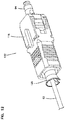
- FIG. 12 is a perspective view of the fiber optic connector of FIG. 11 ;
- FIG. 13 is a perspective schematic view of an example hole forming tool in accordance with the principles of the present disclosure.
- the present disclosure generally relates to a field installable cable system that can be used in a microduct system for FTTx installation.
- a typical passive FTTP network includes fiber optic cables routed from a central location (e.g., a service provider's central office) to an outer edge of the network where subscribers are located.
- FTTx networks can utilize an architecture having centralized optical splitting (e.g., power splitting at hubs such as fiber distribution hubs). This type of architecture can be referred to as a “star” architecture where a hub is the center of the star and distribution cables radiate out from the hub.
- Distributed split architectures can also be used where optical splitting is more distributed through the network. Regardless of the architecture, there is a need to effectively use microducts to extend the network at reduced cost.
- Micro-ducts are often a preferred option for extending fiber optic networks.
- One advantage of micro-ducts relates to the ease of installation allowed by their relatively small cross-sectional size.
- micro-ducts can effectively be installed in narrow trenches which are particularly useful for routing fiber optic drop lines from the curb or other location near the edge of a fiber optic network to a subscriber location.
- micro-ducts can have outer diameters equal to or less than 8.5 mm and inner diameters equal to or less than 6 mm.
- fiber optic cabling assemblies adapted to effectively be routed through micro-ducts.
- fiber optic cable assemblies in accordance with the principles of the present disclosure can be configured to be capable of being pushed through a relatively long micro-duct (e.g., a micro-duct in excess of 1000 feet). In this way, it is not required use blowing equipment and a pulling line is not required to be pre-routed through the micro-duct.
- Fiber optic cable assemblies in accordance with the principles of the present disclosure are preferably relatively small in cross-sectional size and are also configured to be at least partially pre-connectorized.
- a ferrule can be pre-mounted (e.g., factory installed) at the end of an optical fiber of the fiber optic cable assembly prior to the fiber optic cable assembly being routed through a micro-duct.
- This is advantageous because such a configuration eliminates the need for fiber optic connectors to be field spliced to the fiber optic cable after routing through the micro-ducts. Eliminating the field installation of fiber optic connectors can greatly reduce installation times and can reduce the level of skill required by the installer.
- FIG. 1 is a perspective view of an end of a length of an example pushable fiber optic cable 12 for deployment through a conduct in accordance with principles of the present disclosure.
- the pushable fiber optic cable 12 includes an inner core with a single optical fiber 46 for transmitting data signals.
- the optical fiber 46 may be a 250 micron diameter optical fiber, although alternatives are possible.
- the optical fiber 46 can be centrally located along a center axis 48 of the fiber optic cable 12 .
- the fiber optic cable 12 includes an optional buffer tube 50 that surrounds the optical fiber 46 .
- the buffer tube 50 is centered along the center axis 48 of the fiber optic cable 12 .
- optical fiber 46 may be located within the buffer tube 50 , such as two, four, eight, or even up to 24 optical fibers.
- the optical fiber 46 may be positioned loosely within the buffer tube 5 to provide a “loose-tube arrangement” or may be positioned to provide a “tight-tube” arrangement.
- the inner core of the fiber optic cable 12 may include a plurality of strength members 52 .
- the plurality of strength members 52 are fibers or yarns that completely surround the buffer tube 50 .
- the yarns may be constructed of aramid yarns, such as those sold under the trademark of Kevlar.
- the fiber optic cable 12 includes at least on rigid strength member 54 within the inner core.
- three glass reinforced plastic (GRP) rods 54 a , 54 b , 54 c are spaced evenly around the buffer tube 50 (e.g., at equal intervals of one hundred twenty degrees apart), although alternatives are possible.
- two rigid strength members 54 may be used and spaced one hundred and eighty degrees apart such that they are positioned on opposite sides of the buffer tube 50 .
- the rigid strength members 54 are disposed within the strength members 52 .
- the rigid strength members 54 impart rigidity to the overall fiber optic cable 12 , which allows the fiber optic cable 12 to be pushed into the conduit and follow a straight line.
- GRP rods have been described, other types of rigid rods may be used.
- the fiber optic cable 12 includes a jacket 56 that surrounds the inner core.
- the jacket 56 surrounds the optical fiber 46 , the buffer tube 50 , the strength members 52 , and the rigid strength members 54 a - c .
- the jacket 56 has an undulating thickness entirely around the inner core to form a plurality of alternating projections 58 and valleys 60 on an outer surface of the jacket 56 .
- the projections 58 and valleys 60 extend along the length of the fiber optic cable 12 .
- the projections 58 will not deform or fold over when encountered by interior portions of a conduit.
- the fluted outer shape helps to reduce friction between the jacket 56 of the fiber optic cable 12 and an interior wall of a conduit. As such, the length of deployed fiber optic cable 12 increases without a need for lubricants or air.
- the fiber optic cable 12 can be suitable for a broad range of uses (i.e., pushing installation, blowing installation, as well as indoor and outdoor applications).
- the jacket material i.e., the outer sheath
- the jacket 56 may be formed of a low smoke zero halogen (LSZH) material, although alternatives are possible.
- the overall diameter of the fiber optic cable 12 is about 5.0 millimeters (mm). In certain examples, the overall diameter of the fiber optic cable 12 is about 3.5 mm.
- Example low friction pushable cables can be found in U.S. Provisional Patent Application No. 62/453,391, filed Feb. 1, 2017, and titled “Low Friction Fluted LSZH Indoor/Outdoor Optic Fiber Cable,” the disclosure of which is incorporated herein by reference.
- the example field installable cable system 10 can include the example pushable fiber optic cable 12 , a fiber optic ferrule assembly 64 (see FIG. 4 ), a protective tube 14 adapted to cover the fiber optic ferrule assembly 64 , and a coupling member 16 (e.g., connector) for attaching the protective tube 14 to the fiber optic cable 12 .
- a coupling member 16 e.g., connector
- the protective tube 14 includes a circumferential wall 70 that has a first open end 72 , a second open end 74 , and an outside diameter OD (e.g., outer diameter).
- the outside diameter OD of the circumferential wall 70 of the protective tube 14 can be slightly smaller than that of a micro-duct through which the protective tube 14 is routed.
- the outside diameter OD of the circumferential wall 70 of the protective tube 14 is no more than 5.5 mm. In certain examples, the outside diameter OD of the circumferential wall 70 of the protective tube 14 is less than 6.0 mm.
- the circumferential wall 70 of the protective tube 14 can have a wall thickness T of about 0.4 mm, although alternatives are possible. In certain examples, the wall thickness T of the circumferential wall 70 of the protective tube 14 can be less than about 0.4 mm. In certain examples, the wall thickness T of the circumferential wall 70 of the protective tube 14 can have a constant thickness between the first and second open ends 72 , 74 and around a circumference thereof.
- the protective tube 14 can have a longitudinal length L that extends from the first open end 72 to the second open end 74 .
- the longitudinal length L of the protective tube 14 can range from about 400 mm to about 600 mm, although alternatives are possible.
- the first and second open ends 72 , 74 of the protective tube 14 each define a first hole 76 and a second hole 78 .
- the first and second holes 76 , 78 have a largest outer diameter of no more than 2 mm. In certain examples, the first and second holes 76 , 78 have a largest outer diameter of no more than 3 mm. In certain examples, the first and second holes 76 , 78 have a largest outer diameter of no more than 4 mm.
- the first hole 76 extends through a first sidewall 80 of the protective tube 14 , from an outside surface 82 to an inside surface 84 thereof.
- the second hole 78 extends through a second sidewall 86 of the protective tube, from the outside surface 82 to the inside surface 84 thereof.
- the first and second holes 76 , 78 can each be aligned relative to one another on opposite sides of the protective tube 14 , although alternative configurations are possible.
- the protective tube 14 further defining a bore 88 .
- the first and second open ends 72 , 74 of the protective tube 14 may define one single hole. In other examples, the first and second open ends 72 , 74 of the protective tube 14 may define more than two holes.
- the protective tube 14 may be constructed as a thin-walled, strong, round tube, made of a polymeric material.
- the polymeric material includes polytetrafluoroethylene (e.g., trademark name Teflon®).
- Teflon® polytetrafluoroethylene
- the protective tube 14 as designed according to the present disclosure, achieves certain advantages, such as providing ultra low friction due to its slippery properties, which is especially suited for installation in small microducts, holes, or other paths.
- the protective tube 14 is also flexible enough to be easily deployed or pushed through microducts.
- the protective tube 14 has a small outer diameter that is especially suited for installation in small microducts.
- the protective tube 14 provides excellent protection against water, dirt, dust, etc. microbending, and mechanical damage.
- the fiber optic ferrule assembly 64 includes a fiber optic ferrule 90 and a ferrule hub 92 .
- a keying member 44 mounts over the ferrule hub 92 .
- the fiber optic ferrule 90 and the ferrule hub 92 are secured together by convenient methods including press fit or adhesive mounts.
- the fiber optic ferrule assembly 64 may also include a spring 96 that also mounts over the ferrule hub 92 and positioned there behind.
- the pushable fiber optic cable 12 includes an optical fiber 62 that is terminated within the fiber optic ferrule assembly 64 in a fiber processing procedure.
- the fiber optic ferrule 90 can have a front end 66 and a rear end 68 opposite the front end 66 .
- a portion of the optical fiber 62 can extend rearwardly from the rear end 68 of the fiber optic ferrule 90 .
- the ferrule hub 92 surrounds the rear end 68 of the fiber optic ferrule 90 .
- a tip of the optical fiber 62 and an end face of the ferrule are preferably polished.
- the optical fiber 62 and/or the fiber optic ferrule 90 are tuned and cleaned.
- a dust cap 94 is disposed over the front end 66 of the fiber optic ferrule 90 to cover the fiber tip.
- the dust cap 94 is friction fit to the fiber optic ferrule 90 in an axially fixed position until a predetermine amount of axial force is applied to the dust cap 94 .
- the fiber processing procedure from insertion of the fiber into the ferrule to mounting the dust cap, occurs in a factory.
- the dust cap 94 maintains the cleanliness of the fiber tip during shipping and installation.
- the protective tube 14 can be mounted around the fiber optic ferrule assembly 64 to cover the fiber optic ferrule assembly 64 which can then be pushed through a hole, microduct, or other path. That is, the fiber optic ferrule 90 , ferrule hub 92 , spring 96 , and dust cap 94 can be positioned within the bore 88 of the protective tube 14 for deployment through a hole, microduct, or other path.
- the overall weight of the fiber optic ferrule assembly 64 and protective tube 14 is no more than 0.2 ounces (oz), although alternatives are possible. In certain examples, the weight of the field installable cable system 10 is about 0.1 oz.
- the protective tube 14 is configured to hold the components of the fiber optic ferrule assembly 64 in axially fixed positons relative to each other and relative to the protective tube 14 during installation. In certain examples, the protective tube 14 also is configured to hold the fiber optic ferrule assembly 64 in a rotationally fixed position relative to the protective tube 14 during installation.
- the small size of the protective tube 14 including the fiber optic ferrule assembly 64 allows the protective tube 14 and fiber optic ferrule assembly 64 to be readily routed through a microduct, hole, or other path in the field.
- the protective tube 14 can be pushed through a microduct, hole, or other path that has an inside diameter (e.g., inner diameter) of no more than 6 mm, although alternatives are possible.
- a maximum cross-dimension of a connector is less than or equal to the outer diameter OD of the protective tube 14 .
- FIG. 5 a schematic cross-sectional view of the coupling member 16 which can be removably connected to the fiber optic cable 12 and the protective tube 14 .
- FIGS. 6-7 depict schematic views of the coupling member 16 .
- the coupling member 16 has a main body 98 with a distal end 100 and a proximal end 102 .
- the distal end 100 of the coupling member 16 is adapted to mount over the jacket 56 of the fiber optic cable 12 .
- the distal end 100 of the coupling member 16 can include internal threaded surfaces 104 . When the coupling member 16 is threaded onto the fiber optic cable 12 , the internal threaded surfaces 104 engage the jacket 56 of the fiber optic cable 12 to secure the coupling member 16 thereon.
- the proximal end 102 of the coupling member 16 can be mounted within the bore 88 of the protective tube 14 at the first open end 72 .
- the proximal end 102 of the coupling member 16 can include first and second tabs 106 a , 106 b that are positioned on opposite sides of the main body 98 of the coupling member 16 .
- the first and second tabs 106 a , 106 b can be integrally formed with the main body 98 of the coupling member 16 , although alternatives are possible.
- the coupling member 16 also has a nut 108 to assist in tightening the threaded coupling member 16 onto the fiber optic cable 12 .
- the nut 108 can have an external flat-sided shape (e.g., octagon shape) with an outer diameter of no more than 5 mm, although alternatives are possible.
- the coupling member 16 can also include an internal hex 132 for utilizing tools that can assist twist-on effort.
- the first and second tabs 106 a , 106 b can extend a distance through the first and second holes 76 , 78 , respectively, for connecting the coupling member 16 to the protective tube 14 .
- the connection is depicted as a “twist-on” and “twist-off” type of attachment, it will be appreciated that other fixation operations may be used.
- the coupling member 16 may have chamfered surfaces to assist with insertion into the protective tube 14 .
- the distal end 100 of the coupling member 16 may also include the first and second tabs 106 a , 106 b such that the coupling member 16 can provide a connection at both the distal and proximal ends 100 , 102 . It will be appreciated that the coupling member 16 can be used at both ends of the protective tube 14 . In certain examples, the coupling member 16 can also be mounted in the second open end 74 of the protective tube 14 to be used as a standalone end cap or a seal (e.g., packaging tip) which may also assist with installation distances.
- the first and second tabs 106 a , 106 b can extend a distance through the first and second holes 76 , 78 , respectively, for connecting the coupling member 16 to the protective tube 14 at the second open end 74 .
- the coupling member 16 can be used as a cable attachment and/or a seal.
- the first and second tabs 106 a , 106 b can have a thickness T 1 equal to or less than the constant thickness T of the circumferential wall 70 of the protective tube 14 .
- the distance di the first and second tabs 106 a , 106 b extend into the first and second holes 76 , 78 , respectively, is less than the constant thickness T of the circumferential wall 70 of the protective tube 14 .
- the first and second tabs 106 a , 106 b extend radially into the first and second holes 76 , 78 , respectively, at a distance di that is approximately one-half of the constant thickness T of the circumferential wall 70 of the protective tube 14 .
- the configuration of the field installable cable system 10 remains small enough such that it can easily fit in a microduct, hole, or other path.
- the field installable cable system 10 is configured to allow the fiber optic cable 12 to be pushed at increased distances with reduced buckling and bending through a microduct, hole, or other path.
- the coupling member 16 can be detached of otherwise removed from the protective tube 14 by rotating the coupling member 16 approximately 90 degrees such that the first and second tabs 106 a , 106 b can disengage from the first and second holes 76 , 78 , respectively.
- the protective tube 14 can be pulled generally in a direction D and disconnected from the coupling member 16 such that the remaining connector parts can be assembled on the fiber optic ferrule assembly 64 .
- FIG. 10 depicts a field installable subassembly 110 that has fiber optic connector components (e.g., housings, shells, seals, keys, plugs, etc.) that can be quickly and easily mounted over the fiber optic ferrule assembly 64 in the field.
- fiber optic connector components e.g., housings, shells, seals, keys, plugs, etc.
- Example fiber optic connector and assembly can be found in PCT International Patent Application No. PCT/US2016/064223, filed Nov. 30, 2016, and titled “Fiber Optic Connector and Assembly Thereof,” the disclosure of which is incorporated herein by reference.
- FIGS. 11-12 show the field installable subassembly 110 installed around the fiber optic ferrule assembly 64 to configure an example optical connector 122 .
- the field installable subassembly 110 includes a proximal connector housing 112 and a distal connector housing 114 .
- a grip body 116 can be mounted over the distal connector housing 114 .
- the fiber optic ferrule assembly 64 can be connectorized with an LC connector, an ST connector, an FC connector, an LX.5 connector, or any other desired connector. The assembled connector body is plugged into a port at the connection destination.
- the proximal connector housing 112 can be installed over the fiber optic ferrule assembly 64 .
- the fiber optic ferrule assembly 64 is sandwiched between the proximal connector housing 112 and the distal connector housing 114 .
- the grip body 116 is mounted to the distal connector housing 114 prior to assembly of the proximal connector housing 112 and the distal connector housing 114 . In other examples, the grip body 116 is mounted to the distal connector housing 114 after assembly of the proximal connector housing 112 and the distal connector housing 114 .
- the proximal connector housing 112 engages the keying member 44 to rotationally retain the keying member 44 (and hence the ferrule hub 92 ) relative to the proximal connector housing 112 .
- the proximal connector housing 112 also axially limits movement of the ferrule hub 92 and the fiber optic ferrule 90 relative to the proximal connector housing 112 .
- the proximal connector housing 112 includes latch members 118 configured to hold the proximal connector housing 112 to the distal connector housing 114 .
- the proximal connector housing 112 has two latch members 118 on opposite sides of the circumference of the proximal connector housing 112 .
- the distal connector housing 114 defines an interior keying region configured to receive the ferrule hub 92 .
- the keying region of the distal connector housing 114 defines a plurality of flat surfaces.
- the keying region has a hex shape.
- the proximal connector housing 112 defines a frustro-conical tail 120 that accommodates lateral pulling and bending of the optical fiber 62 as the optical fiber 62 exits the proximal connector housing 112 .
- the rear of the proximal connector housing 112 is configured to mitigate the need for a separate strain-relief boot at the rear of the fiber optic connector 122 .
- the frustro-conical tail 120 may obviate the need for a separate strain-relief boot. Accordingly, the example fiber optic connector 122 does not include a separate strain-relief boot.
- the connector housing 13 can be one of a variety of well known connector types, including SC, FC, ST, LX.5, LC, and others. It will be appreciated that the fiber optic ferrule assembly 64 can be compatible with a number of different categories/types of field installable subassemblies 110 each corresponding to a different style or type of connector.
- the different types of connectors can include hardened and non-hardened.
- the installer can select from a number of different connector styles so that the factory terminated subassembly can be converted into a fiber optic connector that is compatible with the type of fiber adapter encountered in the field.
- the hole forming tool 126 may be used to create holes in the sides of the protective tube 14 , in accordance with the principles of the present disclosure.
- the hole forming tool 126 includes a stop 128 for the protective tube 14 when the protective tube 14 is positioned thereon.
- the hole forming tool 126 also includes a guide hole 130 for receiving a drill bit or other mechanism for creating holes in the sides of the protective tube 14 .
- a hole punch type mechanism may be used to create the holes in the protective tube 14 .
- pins used to create the holes have a largest outer diameter of no more than 3.0 mm. In certain examples, pins used to create the holes have an outer diameter of 2.8 mm.
Abstract
Description
Claims (16)
Priority Applications (1)
| Application Number | Priority Date | Filing Date | Title |
|---|---|---|---|
| US16/955,540 US11221456B2 (en) | 2017-12-19 | 2018-12-19 | Protective tube for micro-duct installation of fiber optic cable |
Applications Claiming Priority (3)
| Application Number | Priority Date | Filing Date | Title |
|---|---|---|---|
| US201762607639P | 2017-12-19 | 2017-12-19 | |
| PCT/US2018/066466 WO2019126303A1 (en) | 2017-12-19 | 2018-12-19 | Protective tube for micro-duct installation of fiber optic cable |
| US16/955,540 US11221456B2 (en) | 2017-12-19 | 2018-12-19 | Protective tube for micro-duct installation of fiber optic cable |
Publications (2)
| Publication Number | Publication Date |
|---|---|
| US20210003801A1 US20210003801A1 (en) | 2021-01-07 |
| US11221456B2 true US11221456B2 (en) | 2022-01-11 |
Family
ID=66993905
Family Applications (1)
| Application Number | Title | Priority Date | Filing Date |
|---|---|---|---|
| US16/955,540 Active US11221456B2 (en) | 2017-12-19 | 2018-12-19 | Protective tube for micro-duct installation of fiber optic cable |
Country Status (2)
| Country | Link |
|---|---|
| US (1) | US11221456B2 (en) |
| WO (1) | WO2019126303A1 (en) |
Families Citing this family (4)
| Publication number | Priority date | Publication date | Assignee | Title |
|---|---|---|---|---|
| US11579357B2 (en) | 2018-03-20 | 2023-02-14 | Commscope Technologies Llc | Fiber optic cable terminal with a pushable stub cable |
| US11422312B2 (en) * | 2019-05-09 | 2022-08-23 | Commscope Technologies Llc | Fiber optic converter |
| FR3118206B1 (en) * | 2020-12-23 | 2024-03-15 | Nexans | Network of tubes for optical cables |
| WO2024029268A1 (en) * | 2022-08-03 | 2024-02-08 | 住友電気工業株式会社 | Optical cable |
Citations (6)
| Publication number | Priority date | Publication date | Assignee | Title |
|---|---|---|---|---|
| US20100254659A1 (en) | 2005-06-08 | 2010-10-07 | Anderson Timothy W | Methods for Forming Connectorized Fiber Optic Cabling |
| US20150241639A1 (en) | 2012-09-27 | 2015-08-27 | Adc Telecommunications, Inc. | Ruggedized multi-fiber fiber optic connector with sealed dust cap |
| US20160202431A1 (en) | 2012-11-14 | 2016-07-14 | Clearfield, Inc. | Optical fiber connector |
| WO2017095928A1 (en) | 2015-11-30 | 2017-06-08 | Commscope Technologies Llc | Fiber optic connector and assembly thereof |
| US20170168245A1 (en) | 2011-03-15 | 2017-06-15 | Commscope Technologies Llc | Fiber optic connector |
| WO2018144529A1 (en) | 2017-02-01 | 2018-08-09 | Commscope Technologies Llc | Low friction indoor/outdoor optic fiber cable with fluted outer shape |
-
2018
- 2018-12-19 WO PCT/US2018/066466 patent/WO2019126303A1/en active Application Filing
- 2018-12-19 US US16/955,540 patent/US11221456B2/en active Active
Patent Citations (6)
| Publication number | Priority date | Publication date | Assignee | Title |
|---|---|---|---|---|
| US20100254659A1 (en) | 2005-06-08 | 2010-10-07 | Anderson Timothy W | Methods for Forming Connectorized Fiber Optic Cabling |
| US20170168245A1 (en) | 2011-03-15 | 2017-06-15 | Commscope Technologies Llc | Fiber optic connector |
| US20150241639A1 (en) | 2012-09-27 | 2015-08-27 | Adc Telecommunications, Inc. | Ruggedized multi-fiber fiber optic connector with sealed dust cap |
| US20160202431A1 (en) | 2012-11-14 | 2016-07-14 | Clearfield, Inc. | Optical fiber connector |
| WO2017095928A1 (en) | 2015-11-30 | 2017-06-08 | Commscope Technologies Llc | Fiber optic connector and assembly thereof |
| WO2018144529A1 (en) | 2017-02-01 | 2018-08-09 | Commscope Technologies Llc | Low friction indoor/outdoor optic fiber cable with fluted outer shape |
Non-Patent Citations (1)
| Title |
|---|
| International Search Report and Written Opinion of the International Searching Authority for corresponding International Patent Application No. PCT/US2018/066466 dated Apr. 16, 2019, 14 pages. |
Also Published As
| Publication number | Publication date |
|---|---|
| WO2019126303A1 (en) | 2019-06-27 |
| US20210003801A1 (en) | 2021-01-07 |
Similar Documents
| Publication | Publication Date | Title |
|---|---|---|
| US11747573B2 (en) | Fiber optic connector and assembly thereof | |
| US11372172B2 (en) | Fiber optic connector with field installable outer connector housing | |
| US11221456B2 (en) | Protective tube for micro-duct installation of fiber optic cable | |
| US7264402B2 (en) | Multi-fiber optic receptacle and plug assembly | |
| US7137742B2 (en) | Fiber optic receptacle and plug assemblies with alignment and keying features | |
| US8506173B2 (en) | Multi-fiber fiber optic receptacle and plug assembly | |
| US20070025665A1 (en) | Multi-fiber fiber optic assembly | |
| US11493720B2 (en) | Flexible fiber node connector | |
| US20210157065A1 (en) | Asymmetric hardened fiber optic connector assemblies and methods for using the same |
Legal Events
| Date | Code | Title | Description |
|---|---|---|---|
| AS | Assignment |
Owner name: COMMSCOPE TECHNOLOGIES LLC, NORTH CAROLINA Free format text: ASSIGNMENT OF ASSIGNORS INTEREST;ASSIGNOR:OTT, MICHAEL JAMES;REEL/FRAME:052979/0877 Effective date: 20190208 |
|
| FEPP | Fee payment procedure |
Free format text: ENTITY STATUS SET TO UNDISCOUNTED (ORIGINAL EVENT CODE: BIG.); ENTITY STATUS OF PATENT OWNER: LARGE ENTITY |
|
| STPP | Information on status: patent application and granting procedure in general |
Free format text: DOCKETED NEW CASE - READY FOR EXAMINATION |
|
| STPP | Information on status: patent application and granting procedure in general |
Free format text: NON FINAL ACTION MAILED |
|
| STPP | Information on status: patent application and granting procedure in general |
Free format text: RESPONSE TO NON-FINAL OFFICE ACTION ENTERED AND FORWARDED TO EXAMINER |
|
| STPP | Information on status: patent application and granting procedure in general |
Free format text: NOTICE OF ALLOWANCE MAILED -- APPLICATION RECEIVED IN OFFICE OF PUBLICATIONS |
|
| AS | Assignment |
Owner name: JPMORGAN CHASE BANK, N.A., NEW YORK Free format text: ABL SECURITY AGREEMENT;ASSIGNORS:ARRIS ENTERPRISES LLC;COMMSCOPE TECHNOLOGIES LLC;COMMSCOPE, INC. OF NORTH CAROLINA;REEL/FRAME:058843/0712 Effective date: 20211112 Owner name: JPMORGAN CHASE BANK, N.A., NEW YORK Free format text: TERM LOAN SECURITY AGREEMENT;ASSIGNORS:ARRIS ENTERPRISES LLC;COMMSCOPE TECHNOLOGIES LLC;COMMSCOPE, INC. OF NORTH CAROLINA;REEL/FRAME:058875/0449 Effective date: 20211112 |
|
| AS | Assignment |
Owner name: WILMINGTON TRUST, DELAWARE Free format text: SECURITY INTEREST;ASSIGNORS:ARRIS SOLUTIONS, INC.;ARRIS ENTERPRISES LLC;COMMSCOPE TECHNOLOGIES LLC;AND OTHERS;REEL/FRAME:060752/0001 Effective date: 20211115 |
|
| STPP | Information on status: patent application and granting procedure in general |
Free format text: PUBLICATIONS -- ISSUE FEE PAYMENT VERIFIED |
|
| STCF | Information on status: patent grant |
Free format text: PATENTED CASE |