US11221246B2 - Air flow measurement apparatus - Google Patents
Air flow measurement apparatus Download PDFInfo
- Publication number
- US11221246B2 US11221246B2 US17/005,364 US202017005364A US11221246B2 US 11221246 B2 US11221246 B2 US 11221246B2 US 202017005364 A US202017005364 A US 202017005364A US 11221246 B2 US11221246 B2 US 11221246B2
- Authority
- US
- United States
- Prior art keywords
- physical quantity
- circuit board
- flow rate
- passage
- air
- Prior art date
- Legal status (The legal status is an assumption and is not a legal conclusion. Google has not performed a legal analysis and makes no representation as to the accuracy of the status listed.)
- Expired - Fee Related
Links
Images


Classifications
-
- G—PHYSICS
- G01—MEASURING; TESTING
- G01F—MEASURING VOLUME, VOLUME FLOW, MASS FLOW OR LIQUID LEVEL; METERING BY VOLUME
- G01F1/00—Measuring the volume flow or mass flow of fluid or fluent solid material wherein the fluid passes through a meter in a continuous flow
- G01F1/68—Measuring the volume flow or mass flow of fluid or fluent solid material wherein the fluid passes through a meter in a continuous flow by using thermal effects
- G01F1/684—Structural arrangements; Mounting of elements, e.g. in relation to fluid flow
- G01F1/688—Structural arrangements; Mounting of elements, e.g. in relation to fluid flow using a particular type of heating, cooling or sensing element
-
- G—PHYSICS
- G01—MEASURING; TESTING
- G01F—MEASURING VOLUME, VOLUME FLOW, MASS FLOW OR LIQUID LEVEL; METERING BY VOLUME
- G01F5/00—Measuring a proportion of the volume flow
-
- G—PHYSICS
- G01—MEASURING; TESTING
- G01F—MEASURING VOLUME, VOLUME FLOW, MASS FLOW OR LIQUID LEVEL; METERING BY VOLUME
- G01F1/00—Measuring the volume flow or mass flow of fluid or fluent solid material wherein the fluid passes through a meter in a continuous flow
- G01F1/68—Measuring the volume flow or mass flow of fluid or fluent solid material wherein the fluid passes through a meter in a continuous flow by using thermal effects
- G01F1/684—Structural arrangements; Mounting of elements, e.g. in relation to fluid flow
- G01F1/6842—Structural arrangements; Mounting of elements, e.g. in relation to fluid flow with means for influencing the fluid flow
-
- G—PHYSICS
- G01—MEASURING; TESTING
- G01F—MEASURING VOLUME, VOLUME FLOW, MASS FLOW OR LIQUID LEVEL; METERING BY VOLUME
- G01F1/00—Measuring the volume flow or mass flow of fluid or fluent solid material wherein the fluid passes through a meter in a continuous flow
- G01F1/68—Measuring the volume flow or mass flow of fluid or fluent solid material wherein the fluid passes through a meter in a continuous flow by using thermal effects
- G01F1/696—Circuits therefor, e.g. constant-current flow meters
-
- F—MECHANICAL ENGINEERING; LIGHTING; HEATING; WEAPONS; BLASTING
- F02—COMBUSTION ENGINES; HOT-GAS OR COMBUSTION-PRODUCT ENGINE PLANTS
- F02M—SUPPLYING COMBUSTION ENGINES IN GENERAL WITH COMBUSTIBLE MIXTURES OR CONSTITUENTS THEREOF
- F02M35/00—Combustion-air cleaners, air intakes, intake silencers, or induction systems specially adapted for, or arranged on, internal-combustion engines
- F02M35/10—Air intakes; Induction systems
- F02M35/10373—Sensors for intake systems
- F02M35/10386—Sensors for intake systems for flow rate
-
- G—PHYSICS
- G01—MEASURING; TESTING
- G01F—MEASURING VOLUME, VOLUME FLOW, MASS FLOW OR LIQUID LEVEL; METERING BY VOLUME
- G01F1/00—Measuring the volume flow or mass flow of fluid or fluent solid material wherein the fluid passes through a meter in a continuous flow
- G01F1/68—Measuring the volume flow or mass flow of fluid or fluent solid material wherein the fluid passes through a meter in a continuous flow by using thermal effects
- G01F1/684—Structural arrangements; Mounting of elements, e.g. in relation to fluid flow
- G01F1/688—Structural arrangements; Mounting of elements, e.g. in relation to fluid flow using a particular type of heating, cooling or sensing element
- G01F1/69—Structural arrangements; Mounting of elements, e.g. in relation to fluid flow using a particular type of heating, cooling or sensing element of resistive type
Definitions
- the present disclosure relates to an air flow measurement apparatus.
- a sensor device that includes a flow rate sensor, which measures a flow rate of air, and a temperature sensor, which measures the temperature of the air.
- the flow rate sensor and the temperature sensor are installed at a printed circuit board that is in turn installed to a housing.
- an air flow measurement apparatus including: a flow rate sensing device that is placed in a flow rate measurement passage and is configured to output a signal, which corresponds to a flow rate of air flowing in the flow rate measurement passage; a circuit board that is placed in a physical quantity measurement passage; and a physical quantity sensing device that is installed to the circuit board and is configured to output a signal, which corresponds to a physical quantity of the air flowing in the physical quantity measurement passage.
- a physical quantity measurement passage inlet which is communicated with the physical quantity measurement passage, includes a first inner surface and a second inner surface.
- a second distance, which is measured from the physical quantity sensing device to the second inner surface in a plate thickness direction of the circuit board, is larger than a first distance, which is measured from the circuit board to the first inner surface in the plate thickness direction of the circuit board.
- FIG. 1 is a schematic diagram of an engine system, in which an air flow measurement apparatus of respective embodiments of the present disclosure is used.
- FIG. 2 is a front view of an air flow measurement apparatus of a first embodiment.
- FIG. 3 is a side view of the air flow measurement apparatus.
- FIG. 4 is another side view of the air flow measurement apparatus.
- FIG. 5 is a cross-sectional view taken along line V-V in FIG. 2 .
- FIG. 6 is an enlarged cross-sectional view taken along line VI-VI in FIG. 2 .
- FIG. 7 is an enlarged view of an area VII in FIG. 6 .
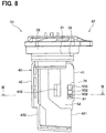
- FIG. 8 is a side view of an air flow measurement apparatus of a second embodiment.
- FIG. 9 is an enlarged cross-sectional view taken along line IX-IX in FIG. 8 .
- FIG. 10 is a front view of an air flow measurement apparatus of a third embodiment.
- FIG. 11 is an enlarged cross-sectional view taken along line XI-XI in FIG. 10 .
- FIG. 12 is a cross-sectional view of a physical quantity sensing device cover of an air flow measurement apparatus of another embodiment.
- FIG. 13 is a cross-sectional view of a circuit board and a circuit board protector of the air flow measurement apparatus of the another embodiment.
- FIG. 14 is a cross-sectional view of a circuit board and a circuit board protector of an air flow measurement apparatus of a further embodiment.
- a sensor device that includes a flow rate sensor, which measures a flow rate of air, and a temperature sensor, which measures the temperature of the air.
- the flow rate sensor and the temperature sensor are installed at a printed circuit board.
- the temperature sensor is installed at a distal end of the elongated printed circuit board such that the temperature sensor is spaced away from an LSI and a microcomputer to limit an influence of heat generated from the LSI and the microcomputer. Furthermore, the circuit board, at which the temperature sensor is installed, is installed to a housing.
- the temperature sensor can be easily influenced by the heat transfer from a portion of the housing, which is opposed to the temperature sensor, since a heat capacity of the temperature sensor is smaller than a heat capacity of the circuit board. Therefore, measurement accuracy of the temperature sensor for measuring the temperature of the air is deteriorated.
- an air flow measurement apparatus including:
- a housing that includes:
- a flow rate sensing device that is placed in the flow rate measurement passage and is configured to output a signal, which corresponds to a flow rate of air flowing in the flow rate measurement passage;
- a physical quantity sensing device that is installed to the circuit board and is configured to output a signal, which corresponds to a physical quantity of the air flowing in the physical quantity measurement passage, wherein:
- the physical quantity measurement passage inlet includes:
- a distance, which is measured from the physical quantity sensing device to the second inner surface in a plate thickness direction of the circuit board, is larger than a distance, which is measured from the circuit board to the first inner surface in the plate thickness direction of the circuit board.
- the flow rate of the air can be measured, and the measurement accuracy of the physical quantity of the air, which is different from the flow rate of the air, can be improved.
- the air flow measurement apparatus 21 is used, for example, in an air intake system of an engine system 100 installed to a vehicle. First of all, this engine system 100 will be described. Specifically, as shown in FIG. 1 , the engine system 100 includes an air intake pipe 11 , an air cleaner 12 , an air flow measurement apparatus 21 , a throttle valve 13 , a throttle sensor 14 , injectors 15 , an engine 16 , an exhaust pipe 17 and an electronic control device 18 .
- intake air refers to air that is drawn into the engine 16 .
- exhaust gas refers to gas that is discharged from the engine 16 .
- the air intake pipe 11 is shaped into a cylindrical tubular form and has an air intake passage 111 .
- the air intake passage 111 is configured to conduct the air to be drawn into the engine 16 .
- the air cleaner 12 is installed in the air intake pipe 11 at an upstream side section of the air intake passage 111 , which is located on an upstream side in a flow direction of the air flowing in the air intake passage 111 . Furthermore, the air cleaner 12 is configured to remove foreign objects, such as dust, contained in the air flowing in the air intake passage 111 .
- the air flow measurement apparatus 21 is located on a downstream side of the air cleaner 12 in the flow direction of the air flowing in the air intake passage 111 .
- the air flow measurement apparatus 21 is configured to measure the flow rate of the air, which flows in the air intake passage 111 , at a location between the air cleaner 12 and the throttle valve 13 .
- the air flow measurement apparatus 21 is also configured to measure a physical quantity of the air that flows in the air intake passage 111 . Details of the air flow measurement apparatus 21 will be described later.
- the physical quantity of the air, which flows in the air intake passage 111 is a physical quantity that is different from the flow rate of the air, which flows in the air intake passage 111 , and this physical quantity is the temperature of the air as discussed later in detail.
- the throttle valve 13 is located on a downstream side of the air flow measurement apparatus 21 in the flow direction of the air flowing in the air intake passage 111 . Furthermore, the throttle valve 13 is shaped into a circular disk form and is rotated by an electric motor (not shown). The throttle valve 13 is configured to adjust a size of a cross-sectional area of the air intake passage 111 and thereby adjust the flow rate of the air to be drawn into the engine 16 through rotation of the throttle valve 13 .
- the throttle sensor 14 is configured to output a measurement signal, which corresponds to an opening degree of the throttle valve 13 , to the electronic control device 18 .
- Each of the injectors 15 is configured to inject the fuel into a corresponding combustion chamber 164 b of the engine 16 based on a signal outputted from the electronic control device 18 described later.
- the engine 16 is an internal combustion engine where a mixture gas, which is a mixture of the air flowing from the air intake passage 111 through the throttle valve 13 and the fuel injected from the injector 15 , is combusted in the combustion chamber 164 .
- An explosive force which is generated by this combustion, causes a piston 162 of the engine 16 to reciprocate in a cylinder 161 .
- the engine 16 includes cylinders 161 , pistons 162 , a cylinder head 163 , combustion chambers 164 , intake valves 165 , an intake valve drive device 166 , exhaust valves 167 , an exhaust valve drive device 168 and spark plugs 169 .
- Each cylinder 161 is shaped in a tubular form and receives the corresponding piston 162 .
- the piston 162 is configured to reciprocate in the corresponding cylinder 161 in an axial direction of the cylinder 161 .
- the cylinder head 163 is installed at upper portions of the cylinders 161 . Furthermore, the cylinder head 163 is connected to the air intake pipe 11 and the exhaust pipe 17 and has primary cylinder passages 181 and secondary cylinder passages 182 .
- Each primary cylinder passage 181 is communicated with the air intake passage 111 .
- Each secondary cylinder passage 182 is communicated with an exhaust passage 171 of the exhaust pipe 17 described later.
- Each combustion chamber 164 is defined by the corresponding cylinder 161 , a top surface of the corresponding piston 162 , and a lower surface of the cylinder head 163 .
- Each intake valve 165 is placed in the corresponding primary cylinder passage 181 and is configured to be driven by the intake valve drive device 166 to open and close the combustion chamber 164 at the primary cylinder passage 181 side.
- Each exhaust valve 167 is placed in the corresponding secondary cylinder passage 182 and is configured to be driven by the exhaust valve drive device 168 to open and close the combustion chamber 164 at the secondary cylinder passage 182 side.
- Each spark plug 169 is configured to ignite the mixture gas of the combustion chamber 164 , which is the mixture of the air flowing from the air intake passage 111 through the throttle valve 13 and the fuel injected from the injector 15 , based on the signal outputted from the electronic control device 18 .
- the exhaust pipe 17 is shaped in a cylindrical tubular form and has the exhaust passage 171 .
- the exhaust passage 171 conducts the gas, which is combusted in the combustion chambers 164 .
- the gas, which flows in the exhaust passage 171 is purified by an exhaust gas purification device (not shown).
- the electronic control device 18 includes a microcomputer as its main component and thereby has a CPU, a ROM, a RAM, an I/O device and a bus line for connecting these devices.
- the electronic control device 18 controls the opening degree of throttle valve 13 based on, for example, the flow rate of the air and the physical quantity of the air measured with the air flow measurement apparatus 21 and the current opening degree of the throttle valve 13 .
- the electronic control device 18 controls a fuel injection amount of the respective injectors 15 and ignition timing of the respective spark plugs 169 based on, for example, the flow rate of the air and the physical quantity of the air measured with the air flow measurement apparatus 21 and the current opening degree of the throttle valve 13 .
- the electronic control device 18 is indicated as an ECU.
- the engine system 100 has the above-described structure. Next, the air flow measurement apparatus 21 will be described in detail.
- the air flow measurement apparatus 21 includes a housing 30 , a flow rate sensing device (a flow rate sensor) 75 , a circuit board 76 , a circuit board protector 77 and a physical quantity sensing device (physical quantity sensor) 81 .
- the housing 30 is installed to a pipe extension 112 that is connected to a peripheral wall of the air intake pipe 11 .
- the pipe extension 112 is shaped in a cylindrical tubular form and extends from the peripheral wall of the air intake pipe 11 from a radially inner side toward a radially outer side in a radial direction of the air intake pipe 11 .
- the housing 30 includes a holding portion 31 , a seal member 32 , a lid 33 , a connector cover 34 , terminals 35 and a bypass portion 40 .
- the holding portion 31 is shaped in a cylindrical tubular form and is fixed to the pipe extension 112 when an outer surface of the holding portion 31 is fitted to an inner surface of the pipe extension 112 . Furthermore, a groove, into which the seal member 32 is fitted, is formed at an outer peripheral surface of the holding portion 31 .
- the seal member 32 is, for example, an O-ring and is installed in the groove of the holding portion 31 .
- the seal member 32 closes a passage in the pipe extension 112 when the seal member 32 contacts the pipe extension 112 . Thereby, leakage of the air flowing in the air intake passage 111 to the outside through the pipe extension 112 is limited.
- the lid 33 is shaped in a bottomed tubular form and is connected to the holding portion 31 in an axial direction of the holding portion 31 . Furthermore, a length of the lid 33 , which is measured in a radial direction of the holding portion 31 , is larger than a diameter of the pipe extension 112 , and the lid 33 closes a hole of the pipe extension 112 .
- the connector cover 34 is connected to the lid 33 and extends from a radially inner side toward a radially outer side in the radial direction of the holding portion 31 . Furthermore, the connector cover 34 is shaped in a tubular form and receives one end portions of the terminals 35 .
- the one end portions of the terminals 35 are received in the connector cover 34 . Furthermore, although not depicted in the drawing, the one end portions of the terminals 35 are connected to the electronic control device 18 . Center portions of the terminals 35 are received in the lid 33 and the holding portion 31 . The other end portions of corresponding ones of the terminals 35 are connected to the circuit board 76 described later.
- the bypass portion 40 includes a plurality of passages and is shaped in a planar form. Specifically, as shown in FIGS. 2 to 6 , the bypass portion 40 includes a housing base surface 41 , a housing back surface 42 , a first housing lateral surface 51 and a second housing lateral surface 52 .
- the bypass portion 40 includes a flow rate measurement main passage inlet (serving as a flow rate measurement passage inlet) 431 , a flow rate measurement main passage outlet (serving as a flow rate measurement passage outlet) 432 , a flow rate measurement main passage (serving as a flow rate measurement passage) 43 , a flow rate measurement sub-passage inlet 441 , a flow rate measurement sub-passage (serving as a flow rate measurement passage) 44 and flow rate measurement sub-passage outlets 442 .
- the bypass portion 40 includes a physical quantity measurement passage inlet 500 , a physical quantity measurement passage 50 , a plurality of primary physical quantity measurement passage outlets 501 and a plurality of secondary physical quantity measurement passage outlets 502 .
- a side of the bypass portion 40 at which the holding portion 31 of the housing 30 is placed, will be referred to as an upper side (also referred to as an upside). Furthermore, another side of the bypass portion 40 , which is opposite to the holding portion 31 , will be referred to as a lower side (also referred to as a downside).
- the housing base surface 41 is located on an upstream side in the flow direction of the air flowing in the air intake passage 111 .
- the housing back surface 42 is located on a side that is opposite to the housing base surface 41 .
- the first housing lateral surface 51 serves as a first lateral surface and is joined to one end portion of the housing base surface 41 and one end portion of the housing back surface 42 .
- the second housing lateral surface 52 serves as a second lateral surface and is joined to another end portion of the housing base surface 41 and another end portion of the housing back surface 42 , which are opposite to the first housing lateral surface 51 .
- the housing base surface 41 , the housing back surface 42 , the first housing lateral surface 51 and the second housing lateral surface 52 are respectively shaped in a stepped form.
- the flow rate measurement main passage inlet 431 is formed at the housing base surface 41 and introduces a portion of the air, which flows in the air intake passage 111 , into the flow rate measurement main passage 43 .
- the flow rate measurement main passage 43 is communicated with the flow rate measurement main passage inlet 431 and the flow rate measurement main passage outlet 432 .
- the flow rate measurement main passage outlet 432 is formed at the housing back surface 42 .
- the flow rate measurement sub-passage inlet 441 is formed at an upper side of the flow rate measurement main passage 43 and introduces a portion of the air, which flows in the flow rate measurement main passage 43 , into the flow rate measurement sub-passage 44 .
- the flow rate measurement sub-passage 44 is a passage that is branched from a middle of the flow rate measurement main passage 43 .
- the flow rate measurement sub-passage 44 includes an introducing portion 443 , a rear vertical portion 444 , a return portion 445 and a front vertical portion 446 .
- the introducing portion 443 is connected to the flow rate measurement sub-passage inlet 441 and extends from the flow rate measurement sub-passage inlet 441 in an upward direction and also in a direction that is directed from the flow rate measurement sub-passage inlet 441 toward the housing back surface 42 . Thereby, a portion of the air, which flows in the flow rate measurement main passage 43 , can be easily introduced into the flow rate measurement sub-passage 44 .
- the rear vertical portion 444 is connected to an end portion of the introducing portion 443 , which is opposite to the flow rate measurement sub-passage inlet 441 , and the rear vertical portion 444 extends from this end portion of the introducing portion 443 in the upward direction.
- the return portion 445 is connected to an end portion of the rear vertical portion 444 , which is opposite to the introducing portion 443 , and the return portion 445 extends from this end portion of the rear vertical portion 444 toward the housing base surface 41 .
- the front vertical portion 446 is connected to an end portion of the return portion 445 , which is opposite to the rear vertical portion 444 , and the front vertical portion 446 extends from this end portion of the return portion 445 in the downward direction.
- FIG. 5 in order to clearly indicate the respective passages, an outline of the flow rate measurement sub-passage inlet 441 , an outline of the second physical quantity measurement passage outlet 502 described later, and an outline of the circuit board 76 are omitted.
- the flow rate measurement sub-passage outlets 442 are respectively formed at the first housing lateral surface 51 and the second housing lateral surface 52 and are communicated with the front vertical portion 446 and the outside of the housing 30 .
- the physical quantity measurement passage inlet 500 (serving as a single physical quantity measurement passage inlet) 500 is formed at the housing base surface 41 at a location, which is on the upper side of the flow rate measurement main passage inlet 431 .
- the physical quantity measurement passage inlet 500 introduces a portion of the air, which flows in the air intake passage 111 , into the physical quantity measurement passage 50 .
- the physical quantity measurement passage 50 communicates the physical quantity measurement passage inlet 500 to the primary physical quantity measurement passage outlets 501 and the secondary physical quantity measurement passage outlets 502 .
- the primary physical quantity measurement passage outlets 501 are formed at the first housing lateral surface 51 .
- the secondary physical quantity measurement passage outlets 502 are formed at the second housing lateral surface 52 .
- the physical quantity measurement passage inlet 500 has a first housing inner surface 61 and a second housing inner surface 62 .
- the first housing inner surface 61 serves as a first inner surface and is located at one side of the physical quantity measurement passage inlet 500 , at which the first housing lateral surface 51 is placed, and the first housing inner surface 61 is joined to the housing base surface 41 .
- the second housing inner surface 62 serves as a second inner surface and is located at the other side of the physical quantity measurement passage inlet 500 , at which the second housing lateral surface 52 is placed, and the second housing inner surface 62 is joined to the housing base surface 41 .
- the flow rate sensing device 75 is installed in the return portion 445 of the flow rate measurement sub-passage 44 and is configured to output a signal that corresponds to the flow rate of the air flowing in the flow rate measurement sub-passage 44 .
- the flow rate sensing device 75 includes a semiconductor that has a heating element and a thermosensitive element. This semiconductor contacts the air flowing in the flow rate measurement sub-passage 44 and thereby performs heat transmission between the semiconductor and the air flowing in the flow rate measurement sub-passage 44 . Due to this heat transmission, the temperature of the semiconductor changes. This temperature changes correlates to the flow rate of the air flowing in the flow rate measurement sub-passage 44 .
- the flow rate sensing device 75 a signal, which corresponds to this temperature change, is outputted, and thereby the flow rate sensing device 75 outputs a signal that corresponds to the flow rate of the air flowing in the flow rate measurement sub-passage 44 . Furthermore, the flow rate sensing device 75 is electrically connected to the other end portion of the corresponding terminal 35 . In this way, the output signal of the flow rate sensing device 75 is transmitted to the electronic control device 18 through the terminal 35 .
- the circuit board 76 is, for example, a printed circuit board and is electrically connected to the other end portions of the corresponding terminals 35 . Furthermore, as shown in FIGS. 2 and 6 , the circuit board 76 is placed in the physical quantity measurement passage 50 . Also, the circuit board 76 is opposed to the first housing inner surface 61 , the second housing inner surface 62 , the primary physical quantity measurement passage outlets 501 and the secondary physical quantity measurement passage outlets 502 . Furthermore, an end portion of the circuit board 76 , which is located on the first housing inner surface 61 side, will be referred to as a first circuit board end portion 761 . Furthermore, another end portion of the circuit board 76 , which is located on the second housing inner surface 62 side, is referred to as a second circuit board end portion 762 .
- the circuit board protector 77 is formed by coating a resin material to a surface of the circuit board 76 , which extends in a plate thickness direction of the circuit board 76 that is perpendicular to a plane of the circuit board 76 .
- the circuit board protector 77 is opposed to the physical quantity measurement passage inlet 500 and covers the surface of the circuit board 76 , which extends in the plate thickness direction of the circuit board 76 , to protect the circuit board 76 .
- an outer periphery of the circuit board protector 77 is curved.
- a center of curvature Ob of the outer periphery of the circuit board protector 77 is located at an inside of one of the circuit board 76 and the circuit board protector 77 , and the outer periphery of the circuit board protector 77 is convexly curved.
- the outer periphery of the circuit board protector 77 has a semi-circular shape, and the center of curvature Ob is located at a boundary surface 763 that is the boundary between the circuit board 76 and the circuit board protector 77 .
- the physical quantity sensing device 81 is installed to the second circuit board end portion 762 of the circuit board 76 and is placed in the physical quantity measurement passage 50 . Furthermore, as shown in FIG. 2 , the physical quantity sensing device 81 is opposed to the physical quantity measurement passage inlet 500 . Also, as shown in FIGS. 4 and 6 , the physical quantity sensing device 81 is opposed to one of the secondary physical quantity measurement passage outlets 502 and is also opposed to the second housing inner surface 62 .
- a distance, which is measured from the first housing inner surface 61 to the first circuit board end portion 761 in the plate thickness direction of the circuit board 76 is defined as a first distance L 1 .
- a distance, which is measured from the second housing inner surface 62 to the physical quantity sensing device 81 in the plate thickness direction of the circuit board 76 is defined as a second distance L 2 .
- the second distance L 2 is larger than the first distance L 1 .
- the first distance L 1 is larger than zero, and the first circuit board end portion 761 is not in contact with the first housing inner surface 61 .
- the physical quantity sensing device 81 outputs a signal that corresponds to the physical quantity of the air, which flows in the physical quantity measurement passage 50 .
- the physical quantity of the air, which flows in the physical quantity measurement passage 50 is the temperature of the air, which flows in the physical quantity measurement passage 50 .
- the physical quantity sensing device (more specifically a temperature sensor in this particular instance) 81 includes a thermistor (not shown) and outputs a signal that corresponds to the temperature of the air, which flows in the physical quantity measurement passage 50 .
- the physical quantity sensing device 81 is installed to the circuit board 76 , so that the output signal of the physical quantity sensing device 81 is transmitted to the electronic control device 18 through the circuit board 76 and the corresponding terminal 35 .
- the air flow measurement apparatus 21 is constructed in the above-described manner. Next, the way of measuring the flow rate and the temperature with the air flow measurement apparatus 21 will be described.
- a portion of the air, which flows in the flow rate measurement main passage 43 is discharged to the outside of the housing 30 through the flow rate measurement main passage outlet 432 .
- the flow rate measurement sub-passage inlet 441 Another portion of the air, which flows in the flow rate measurement main passage 43 , flows into the flow rate measurement sub-passage inlet 441 .
- the air, which flows from the flow rate measurement sub-passage inlet 441 flows in the return portion 445 after passing through the introducing portion 443 and the rear vertical portion 444 of the flow rate measurement sub-passage 44 .
- the portion of the air, which flows in the return portion 445 contacts the flow rate sensing device 75 . Due to the contact of the flow rate sensing device 75 with the air, the flow rate sensing device 75 outputs a signal that corresponds to the flow rate of the air, which flows in the flow rate measurement sub-passage 44 .
- the output signal of the flow rate sensing device 75 is transmitted to the electronic control device 18 through the corresponding terminal 35 . Furthermore, the portion of the air, which flows in the return portion 445 , is discharged to the outside of the housing 30 through the front vertical portion 446 and the flow rate measurement sub-passage outlets 442 of the flow rate measurement sub-passage 44 .
- a portion of the air, which flows in the air intake passage 111 flows into the physical quantity measurement passage inlet 500 .
- the air, which flows into the physical quantity measurement passage inlet 500 flows through the physical quantity measurement passage 50 .
- a portion of the air, which flows in the physical quantity measurement passage 50 contacts the physical quantity sensing device 81 . Due to the contact of the physical quantity sensing device 81 with the air, the physical quantity sensing device 81 outputs a signal that corresponds to the temperature of the air, which flows in the physical quantity measurement passage 50 .
- the output signal of the physical quantity sensing device 81 is transmitted to the electronic control device 18 through the circuit board 76 and the corresponding terminal 35 .
- the air, which flows in the physical quantity measurement passage 50 is discharged to the outside of the housing 30 through the primary physical quantity measurement passage outlets 501 and the secondary physical quantity measurement passage outlets 502 .
- the air flow measurement apparatus 21 measures the flow rate of the air and the temperature of the air.
- the measurement accuracy of the temperature of the air is improved in the air flow measurement apparatus 21 described above. In the following description, the improvement of the measurement accuracy will be described.
- the second distance L 2 is larger than the first distance L 1 .
- the distance, which is measured from the second housing inner surface 62 to the physical quantity sensing device 81 becomes relatively large, so that the amount of heat, which is transmitted from the second housing inner surface 62 to the physical quantity sensing device 81 through the air flowing between the second housing inner surface 62 and the physical quantity sensing device 81 , becomes relatively small.
- a size of a passage cross-sectional area between the second housing inner surface 62 and the physical quantity sensing device 81 becomes relatively large, the flow rate of the air, which flows between the second housing inner surface 62 and the physical quantity sensing device 81 , becomes relatively large. Therefore, the physical quantity sensing device 81 is easily cooled.
- the physical quantity sensing device 81 is less likely to be influenced by the heat transmission from the housing 30 , and thereby the air flow measurement apparatus 21 can improve the measurement accuracy of the temperature of the air.
- the air flow measurement apparatus 21 provides advantages discussed in the following sections [1] to [3].
- the first distance L 1 is larger than zero, and the first circuit board end portion 761 is not in contact with the first housing inner surface 61 .
- the heat is no longer conducted from the first housing inner surface 61 to the first circuit board end portion 761 , and thereby the amount of heat conducted from the housing 30 to the circuit board 76 is reduced.
- the amount of heat conducted from the first circuit board end portion 761 to the second circuit board end portion 762 becomes relatively small, the amount of heat, which is conducted from the circuit board 76 to the physical quantity sensing device 81 becomes relatively small. Since the physical quantity sensing device 81 is less likely to be influenced by the heat from the circuit board 76 , the physical quantity sensing device 81 can improve the measurement accuracy of the temperature of the air.
- the circuit board protector 77 is opposed to the physical quantity measurement passage inlet 500 and covers the surface of the circuit board 76 , which extends in the plate thickness direction of the circuit board 76 , to protect the circuit board 76 . In this way, the corrosion of the circuit board 76 is limited.
- the center of curvature Ob of the outer periphery of the circuit board protector 77 is located at the inside of the one of the circuit board 76 and the circuit board protector 77 , and the outer periphery of the circuit board protector 77 is convexly curved. Since the outer periphery of the circuit board protector 77 is convexly curved, the air, which flows in the physical quantity measurement passage 50 , flows along the outer periphery of the circuit board protector 77 .
- a pressure loss of the air, which flows through the physical quantity measurement passage 50 is reduced, and a decrease in the flow rate of the air, which flows in the physical quantity measurement passage 50 , is limited.
- the flow rate of the air, which flows in the physical quantity measurement passage 50 becomes relatively large, and thereby the physical quantity sensing device 81 can be easily cooled.
- the physical quantity sensing device 81 is less likely to be influenced by the heat transmission from the housing 30 , and thereby the air flow measurement apparatus 21 can improve the measurement accuracy of the temperature of the air.
- the second embodiment is similar to the first embodiment except that the location of the circuit board and the physical quantity sensing device is different from that of the first embodiment.
- a surface of the circuit board 76 at which the physical quantity sensing device 81 is installed, is directly opposed to the secondary physical quantity measurement passage outlets 502 in a direction perpendicular to the plane of the circuit board 76 .
- the physical quantity sensing device 81 is directly opposed to one of the secondary physical quantity measurement passage outlets 502 in the direction perpendicular to the plane of the circuit board 76 .
- a distance which is measured from the first housing inner surface 61 to a first imaginary line I 1 in the plate thickness direction of the circuit board 76 , serves as the first distance L 1 .
- the first imaginary line I 1 is an imaginary line that extends along the first circuit board end portion 761 in a width direction of the circuit board 76 that is a direction along a width of the circuit board 76 and is perpendicular to the longitudinal direction and the plate thickness direction of the circuit board 76 .
- a distance which is measured from the second housing inner surface 62 to a second imaginary line I 2 in the plate thickness direction of the circuit board 76 , serves as the second distance L 2 .
- the second imaginary line I 2 is an imaginary line that extends along the physical quantity sensing device 81 in the width direction of the circuit board 76 .
- the physical quantity sensing device 81 is opposed to the secondary physical quantity measurement passage outlet 502 . Therefore, in comparison to a case where the physical quantity sensing device 81 is directly opposed to the second housing inner surface 62 , the physical quantity sensing device 81 is less likely to be influenced by the heat transmission from the second housing inner surface 62 .
- the air flow measurement apparatus is similar to that of the first embodiment except that the air flow measurement apparatus of the third embodiment has a physical quantity sensing device cover.
- the air flow measurement apparatus 23 of the third embodiment further includes a physical quantity sensing device cover 85 .
- the physical quantity sensing device cover 85 serves as a cover and covers a portion of the second circuit board end portion 762 and the physical quantity sensing device 81 .
- the physical quantity sensing device cover 85 is formed by potting of a resin material.
- an outer periphery of the physical quantity sensing device cover 85 is curved.
- the outer periphery of the physical quantity sensing device cover 85 has a streamlined shape.
- the streamlined shape is a shape that extends along a streamline of the air, which flows in the physical quantity measurement passage 50 .
- a distance, which is measured from the second housing inner surface 62 to the physical quantity sensing device cover 85 in the plate thickness direction of the circuit board 76 is defined as a third distance L 3 .
- the third distance L 3 is larger than the first distance L 1 .
- the air flow measurement apparatus 23 measures the temperature as follows.
- the air, which flows into the physical quantity measurement passage inlet 500 flows through the physical quantity measurement passage 50 .
- a portion of the air, which flows in the physical quantity measurement passage 50 contacts the physical quantity sensing device cover 85 .
- the heat, which is conducted from the air flowing in the physical quantity measurement passage 50 to the physical quantity sensing device cover 85 is conducted to the physical quantity sensing device 81 through the physical quantity sensing device cover 85 . Due to the heat conducted from the physical quantity sensing device cover 85 to the physical quantity sensing device 81 , the physical quantity sensing device 81 outputs a signal, which corresponds to the temperature of the air flowing in the physical quantity measurement passage 50 .
- the output signal of the physical quantity sensing device 81 is transmitted to the electronic control device 18 through the circuit board 76 and the corresponding terminal 35 like in the first embodiment. Furthermore, the air, which flows in the physical quantity measurement passage 50 , is discharged to the outside of the housing 30 through the primary physical quantity measurement passage outlets 501 and the secondary physical quantity measurement passage outlets 502 like in the first embodiment.
- the physical quantity sensing device 81 is covered by the physical quantity sensing device cover 85 in the air flow measurement apparatus 21 , into which the air flowing in the air intake passage 111 is introduced. Thereby, the corrosion of the physical quantity sensing device 81 is limited.
- an outer periphery of the physical quantity sensing device cover 85 is curved. Therefore, the air, which flows in the physical quantity measurement passage 50 , can more easily flow along the outer periphery of the physical quantity sensing device cover 85 in comparison to a case where the outer periphery of the physical quantity sensing device cover 85 is shaped in a polygonal form. Thus, a pressure loss of the air, which flows in the physical quantity measurement passage 50 , is reduced, and a decrease in the flow rate of the air, which flows in the physical quantity measurement passage 50 , is limited.
- the flow rate of the air, which flows in the physical quantity measurement passage 50 becomes relatively large, and thereby the physical quantity sensing device 81 can be easily cooled.
- the physical quantity sensing device 81 is less likely to be influenced by the heat transmission from the housing 30 , and thereby the air flow measurement apparatus 23 can improve the measurement accuracy of the temperature of the air.
- the physical quantity sensing device 81 outputs the signal, which corresponds to the temperature of the air flowing in the physical quantity measurement passage 50 .
- the physical quantity sensing device 81 should not be limited to the above configuration where the physical quantity sensing device 81 outputs the signal, which corresponds to the temperature of the air flowing in the physical quantity measurement passage 50 , and the physical quantity sensing device 81 may be configured to output a signal, which corresponds to a relative humidity of the air flowing in the physical quantity measurement passage 50 .
- the physical quantity sensing device 81 may output a signal, which corresponds to a pressure of the air flowing in the physical quantity measurement passage 50 .
- the physical quantity sensing device 81 is less likely to be influenced by the heat transmission from the housing 30 , so that the air flow measurement apparatus 21 , 22 , 23 can improve the measurement accuracy of the relative humidity of the air and the measurement accuracy of the pressure of the air.
- the plurality of primary physical quantity measurement passage outlets 501 is formed at the first housing lateral surface 51
- the plurality of secondary physical quantity measurement passage outlets 502 is formed at the second housing lateral surface 52 .
- the secondary physical quantity measurement passage outlets 502 may be eliminated from the second housing lateral surface 52 .
- the primary physical quantity measurement passage outlets 501 may be eliminated from the first housing lateral surface 51 .
- the number of the primary physical quantity measurement passage outlets 501 is three, and the number of the secondary physical quantity measurement passage outlets 502 is three.
- the number of the primary physical quantity measurement passage outlets 501 and the number of the secondary physical quantity measurement passage outlets 502 should not be respectively limited to three.
- the number of the primary physical quantity measurement passage outlets 501 and the number of the secondary physical quantity measurement passage outlets 502 may be respectively set to one, two, four or more.
- the primary physical quantity measurement passage outlets 501 and the secondary physical quantity measurement passage outlets 502 are respectively shaped in an elongated rectangular shape.
- the shape of the respective primary physical quantity measurement passage outlets 501 and the shape of the respective secondary physical quantity measurement passage outlets 502 are not necessarily limited to the elongated rectangular shape and may be a polygonal shape, a circular shape or an elliptical shape.
- the number of the physical quantity measurement passage inlet 500 is one.
- the number of the physical quantity measurement passage inlet 500 is not necessarily limited to one, and there may be provided two or more physical quantity measurement passage inlets 500 .
- the physical quantity measurement passage inlet 500 is shaped in an elongate rectangular shape.
- the shape of the physical quantity measurement passage inlet 500 is not necessarily limited to the elongated rectangular shape and may be a polygonal shape, a circular shape or an elliptical shape.
- the outer periphery of the physical quantity sensing device cover 85 has the streamlined shape.
- the shape of the outer periphery of the physical quantity sensing device cover 85 is not necessarily limited to the streamlined shape.
- the outer periphery of the physical quantity sensing device cover 85 may have a semi-circular shape.
- the air flow measurement apparatus 22 of the second embodiment and the air flow measurement apparatus 23 of the third embodiment may be combined together.
- the air flow measurement apparatus 22 of the second embodiment may have the physical quantity sensing device cover 85 .
- This physical quantity sensing device cover 85 is directly opposed to the one of the secondary physical quantity measurement passage outlets 502 .
- the outer periphery of the circuit board protector 77 has the semi-circular shape.
- the outer periphery of the circuit board protector 77 does not necessarily have the semi-circular shape.
- the outer periphery of the circuit board protector 77 may have an arcuate shape that has a central angle smaller than 180 degrees.
- the center of curvature Ob of the outer periphery of the circuit board protector 77 is located at the inside of the circuit board 76 .
- the outer periphery of the circuit board protector 77 may have an arcuate shape that has a central angle larger than 180 degrees.
- the center of curvature Ob of the outer periphery of the circuit board protector 77 is located at the outside of the circuit board 76 and at the inside of the circuit board protector 77 .
- the outer periphery of the circuit board protector 77 may have a shape that is formed by combining an arc having the center of curvature Ob located at the inside of the circuit board 76 and an arc having the center of curvature Ob located at the inside of the circuit board protector 77 .
- the first housing inner surface 61 and the second housing inner surface 62 are respectively shaped as a planar surface.
- the first housing inner surface 61 and the second housing inner surface 62 are not necessarily respectively shaped as the planar surface.
- the first housing inner surface 61 and the second housing inner surface 62 may be respectively shaped as a curved surface or a stepped surface.
- a minimum distance which is measured from the first housing inner surface 61 to the first circuit board end portion 761 in the plate thickness direction of the circuit board 76 , serves as the first distance L 1 .
- a minimum distance which is measured from the second housing inner surface 62 to the physical quantity sensing device 81 in the plate thickness direction of the circuit board 76 , serves as the second distance L 2 .
- the pipe extension 112 is shaped in the cylindrical tubular form.
- the pipe extension 112 is not necessarily shaped in the cylindrical tubular form.
- the pipe extension 112 may be shaped in another tubular form, such as a polygonal tubular form.
- the holding portion 31 is shaped in the cylindrical tubular form.
- the holding portion 31 is not necessarily shaped in the cylindrical tubular form.
- the holding portion 31 may be shaped in another tubular form, such as a polygonal tubular form.
- the connector cover 34 extends from the radially inner side toward the radially outer side in the radial direction of the holding portion 31 .
- the connector cover 34 does not necessarily extend from the radially inner side toward the radially outer side in the radial direction of the holding portion 31 .
- the connector cover 34 may extend in the axial direction of the holding portion 31 .
- the flow rate measurement sub-passage 44 is the passage that is branched from the middle of the flow rate measurement main passage 43 .
- the flow rate measurement sub-passage 44 is not necessarily limited to the passage that is branched from the middle of the flow rate measurement main passage 43 .
- the flow rate measurement sub-passage 44 may be communicated with the flow rate measurement main passage outlet 432 such that the flow rate measurement main passage 43 and the flow rate measurement sub-passage 44 form one flow passage.
Landscapes
- Physics & Mathematics (AREA)
- Fluid Mechanics (AREA)
- General Physics & Mathematics (AREA)
- Measuring Volume Flow (AREA)
- Measuring Temperature Or Quantity Of Heat (AREA)
Abstract
Description
-
- a base surface;
- a back surface that is located on a side, which is opposite to the base surface;
- a first lateral surface that is joined to one end portion of the base surface and one end portion of the back surface;
- a second lateral surface that is joined to another end portion of the base surface and another end portion of the back surface, which are opposite to the first lateral surface;
- a flow rate measurement passage inlet that is formed at the base surface;
- a flow rate measurement passage outlet that is formed at the back surface;
- a flow rate measurement passage that is communicated with the flow rate measurement passage inlet and the flow rate measurement passage outlet;
- a physical quantity measurement passage inlet that is formed at the base surface;
- a physical quantity measurement passage outlet that is formed at one of the first lateral surface and the second lateral surface; and
- a physical quantity measurement passage that is communicated with the physical quantity measurement passage inlet and the physical quantity measurement passage outlet;
-
- a first inner surface that is located at one side of the physical quantity measurement passage inlet, at which the first lateral surface is placed, wherein the first inner surface is joined to the base surface; and
- a second inner surface that is located at another side of the physical quantity measurement passage inlet, at which the second lateral surface is placed, wherein the second inner surface is joined to the base surface; and
Claims (5)
Applications Claiming Priority (3)
| Application Number | Priority Date | Filing Date | Title |
|---|---|---|---|
| JP2019-161244 | 2019-09-04 | ||
| JP2019161244A JP2021039026A (en) | 2019-09-04 | 2019-09-04 | Air flow measuring device |
| JPJP2019-161244 | 2019-09-04 |
Publications (2)
| Publication Number | Publication Date |
|---|---|
| US20210063217A1 US20210063217A1 (en) | 2021-03-04 |
| US11221246B2 true US11221246B2 (en) | 2022-01-11 |
Family
ID=74565223
Family Applications (1)
| Application Number | Title | Priority Date | Filing Date |
|---|---|---|---|
| US17/005,364 Expired - Fee Related US11221246B2 (en) | 2019-09-04 | 2020-08-28 | Air flow measurement apparatus |
Country Status (3)
| Country | Link |
|---|---|
| US (1) | US11221246B2 (en) |
| JP (1) | JP2021039026A (en) |
| DE (1) | DE102020119830B4 (en) |
Families Citing this family (4)
| Publication number | Priority date | Publication date | Assignee | Title |
|---|---|---|---|---|
| JP7099420B2 (en) * | 2019-09-04 | 2022-07-12 | 株式会社デンソー | Air flow measuring device |
| JP7115446B2 (en) * | 2019-09-04 | 2022-08-09 | 株式会社デンソー | Air flow measuring device |
| US12318545B2 (en) * | 2022-10-20 | 2025-06-03 | Telesair, Inc. | Chamber adaptor and manufacturing method thereof |
| CN116829220A (en) * | 2022-10-20 | 2023-09-29 | 泰利艾尔有限公司 | Chamber adapter and manufacturing method thereof |
Citations (8)
| Publication number | Priority date | Publication date | Assignee | Title |
|---|---|---|---|---|
| US6012432A (en) * | 1997-06-26 | 2000-01-11 | Hitachi, Ltd. | Thermal-type airflow meter, intake air system for an internal combustion engine, and control system for the same |
| US6952968B2 (en) * | 2001-02-21 | 2005-10-11 | Hitachi, Ltd. | Device for detecting physical quantity having a housing with a groove |
| US8215160B2 (en) * | 2009-09-30 | 2012-07-10 | Hitachi Automotive Systems, Ltd. | Sensor structure |
| US8549901B2 (en) * | 2011-02-09 | 2013-10-08 | Hitachi Automotive Systems, Ltd. | Sensor structure |
| JP2018096728A (en) | 2016-12-09 | 2018-06-21 | 日立オートモティブシステムズ株式会社 | Sensor device |
| US10591331B2 (en) * | 2015-09-30 | 2020-03-17 | Hitachi Automotive Systems, Ltd. | Intake temperature detection device and maximum heat generating amount components mounted on a single circuit board |
| US10641630B2 (en) * | 2015-09-30 | 2020-05-05 | Hitachi Automotive Systems, Ltd. | Physical quantity detection device |
| US11137292B2 (en) * | 2016-08-22 | 2021-10-05 | Hitachi Automotive Systems, Ltd. | Physical quantity detecting device |
Family Cites Families (4)
| Publication number | Priority date | Publication date | Assignee | Title |
|---|---|---|---|---|
| JP6208251B2 (en) | 2013-11-07 | 2017-10-04 | 日立オートモティブシステムズ株式会社 | Physical quantity measuring device |
| JP6812688B2 (en) | 2016-07-20 | 2021-01-13 | 株式会社デンソー | Intake flow measuring device |
| JP6670792B2 (en) * | 2017-04-06 | 2020-03-25 | 日立オートモティブシステムズ株式会社 | Physical quantity detection device, method for manufacturing physical quantity detection device |
| JP2018204993A (en) * | 2017-05-31 | 2018-12-27 | 日立オートモティブシステムズ株式会社 | Physical quantity measuring device |
-
2019
- 2019-09-04 JP JP2019161244A patent/JP2021039026A/en active Pending
-
2020
- 2020-07-28 DE DE102020119830.2A patent/DE102020119830B4/en not_active Expired - Fee Related
- 2020-08-28 US US17/005,364 patent/US11221246B2/en not_active Expired - Fee Related
Patent Citations (8)
| Publication number | Priority date | Publication date | Assignee | Title |
|---|---|---|---|---|
| US6012432A (en) * | 1997-06-26 | 2000-01-11 | Hitachi, Ltd. | Thermal-type airflow meter, intake air system for an internal combustion engine, and control system for the same |
| US6952968B2 (en) * | 2001-02-21 | 2005-10-11 | Hitachi, Ltd. | Device for detecting physical quantity having a housing with a groove |
| US8215160B2 (en) * | 2009-09-30 | 2012-07-10 | Hitachi Automotive Systems, Ltd. | Sensor structure |
| US8549901B2 (en) * | 2011-02-09 | 2013-10-08 | Hitachi Automotive Systems, Ltd. | Sensor structure |
| US10591331B2 (en) * | 2015-09-30 | 2020-03-17 | Hitachi Automotive Systems, Ltd. | Intake temperature detection device and maximum heat generating amount components mounted on a single circuit board |
| US10641630B2 (en) * | 2015-09-30 | 2020-05-05 | Hitachi Automotive Systems, Ltd. | Physical quantity detection device |
| US11137292B2 (en) * | 2016-08-22 | 2021-10-05 | Hitachi Automotive Systems, Ltd. | Physical quantity detecting device |
| JP2018096728A (en) | 2016-12-09 | 2018-06-21 | 日立オートモティブシステムズ株式会社 | Sensor device |
Also Published As
| Publication number | Publication date |
|---|---|
| JP2021039026A (en) | 2021-03-11 |
| DE102020119830B4 (en) | 2024-05-23 |
| US20210063217A1 (en) | 2021-03-04 |
| DE102020119830A1 (en) | 2021-03-04 |
Similar Documents
| Publication | Publication Date | Title |
|---|---|---|
| US11221246B2 (en) | Air flow measurement apparatus | |
| EP2306161B1 (en) | Flow rate sensor structure | |
| US8701475B2 (en) | Air flow measuring device | |
| US9851234B2 (en) | Physical quantity measuring device | |
| US10429223B2 (en) | Air flow rate measuring device with integrated sensor module | |
| CN106662476B (en) | Physical Quantity Detection Device | |
| EP3203195B1 (en) | Thermal flow meter | |
| US8844350B2 (en) | Flow quantity measuring apparatus including branched conductive lines connected to midpoints of series circuits of the bridge circuit | |
| US9052223B2 (en) | Air flow quantity measuring apparatus for internal combustion engine | |
| US20220155122A1 (en) | Air flow rate measurement device | |
| US20220155121A1 (en) | Airflow meter | |
| US20220163360A1 (en) | Air flow rate measurement device | |
| JP6995020B2 (en) | Physical quantity detector | |
| US11668256B2 (en) | Mass-flow throttle for large natural gas engines | |
| US20220155119A1 (en) | Air flow rate measurement device | |
| US20210325227A1 (en) | Physical quantity measurement device | |
| US7231909B2 (en) | Air intake apparatus and control apparatus for an internal combustion engine | |
| WO2022123841A1 (en) | Flow rate detection device | |
| US20120181174A1 (en) | Fuel sensor | |
| US20220349736A1 (en) | Air flow rate measuring device | |
| JPH03261826A (en) | hot wire air flow meter |
Legal Events
| Date | Code | Title | Description |
|---|---|---|---|
| AS | Assignment |
Owner name: DENSO CORPORATION, JAPAN Free format text: ASSIGNMENT OF ASSIGNORS INTEREST;ASSIGNORS:TSUCHIYA, TAKUMA;ITOU, KENGO;KITAHARA, NOBORU;AND OTHERS;SIGNING DATES FROM 20200616 TO 20200622;REEL/FRAME:053623/0346 |
|
| FEPP | Fee payment procedure |
Free format text: ENTITY STATUS SET TO UNDISCOUNTED (ORIGINAL EVENT CODE: BIG.); ENTITY STATUS OF PATENT OWNER: LARGE ENTITY |
|
| STPP | Information on status: patent application and granting procedure in general |
Free format text: DOCKETED NEW CASE - READY FOR EXAMINATION |
|
| STPP | Information on status: patent application and granting procedure in general |
Free format text: NOTICE OF ALLOWANCE MAILED -- APPLICATION RECEIVED IN OFFICE OF PUBLICATIONS |
|
| STPP | Information on status: patent application and granting procedure in general |
Free format text: PUBLICATIONS -- ISSUE FEE PAYMENT VERIFIED |
|
| STCF | Information on status: patent grant |
Free format text: PATENTED CASE |
|
| FEPP | Fee payment procedure |
Free format text: MAINTENANCE FEE REMINDER MAILED (ORIGINAL EVENT CODE: REM.); ENTITY STATUS OF PATENT OWNER: LARGE ENTITY |
|
| LAPS | Lapse for failure to pay maintenance fees |
Free format text: PATENT EXPIRED FOR FAILURE TO PAY MAINTENANCE FEES (ORIGINAL EVENT CODE: EXP.); ENTITY STATUS OF PATENT OWNER: LARGE ENTITY |
|
| STCH | Information on status: patent discontinuation |
Free format text: PATENT EXPIRED DUE TO NONPAYMENT OF MAINTENANCE FEES UNDER 37 CFR 1.362 |
|
| FP | Lapsed due to failure to pay maintenance fee |
Effective date: 20260111 |