US11221049B2 - Clutch control method for vehicle - Google Patents
Clutch control method for vehicle Download PDFInfo
- Publication number
- US11221049B2 US11221049B2 US17/019,758 US202017019758A US11221049B2 US 11221049 B2 US11221049 B2 US 11221049B2 US 202017019758 A US202017019758 A US 202017019758A US 11221049 B2 US11221049 B2 US 11221049B2
- Authority
- US
- United States
- Prior art keywords
- clutch
- torque
- predetermined
- refill
- controller
- Prior art date
- Legal status (The legal status is an assumption and is not a legal conclusion. Google has not performed a legal analysis and makes no representation as to the accuracy of the status listed.)
- Active
Links
Images


Classifications
-
- F—MECHANICAL ENGINEERING; LIGHTING; HEATING; WEAPONS; BLASTING
- F16—ENGINEERING ELEMENTS AND UNITS; GENERAL MEASURES FOR PRODUCING AND MAINTAINING EFFECTIVE FUNCTIONING OF MACHINES OR INSTALLATIONS; THERMAL INSULATION IN GENERAL
- F16D—COUPLINGS FOR TRANSMITTING ROTATION; CLUTCHES; BRAKES
- F16D48/00—External control of clutches
- F16D48/06—Control by electric or electronic means, e.g. of fluid pressure
- F16D48/066—Control of fluid pressure, e.g. using an accumulator
-
- F—MECHANICAL ENGINEERING; LIGHTING; HEATING; WEAPONS; BLASTING
- F16—ENGINEERING ELEMENTS AND UNITS; GENERAL MEASURES FOR PRODUCING AND MAINTAINING EFFECTIVE FUNCTIONING OF MACHINES OR INSTALLATIONS; THERMAL INSULATION IN GENERAL
- F16H—GEARING
- F16H59/00—Control inputs to control units of change-speed-, or reversing-gearings for conveying rotary motion
- F16H59/50—Inputs being a function of the status of the machine, e.g. position of doors or safety belts
- F16H59/56—Inputs being a function of the status of the machine, e.g. position of doors or safety belts dependent on signals from the main clutch
-
- F—MECHANICAL ENGINEERING; LIGHTING; HEATING; WEAPONS; BLASTING
- F16—ENGINEERING ELEMENTS AND UNITS; GENERAL MEASURES FOR PRODUCING AND MAINTAINING EFFECTIVE FUNCTIONING OF MACHINES OR INSTALLATIONS; THERMAL INSULATION IN GENERAL
- F16D—COUPLINGS FOR TRANSMITTING ROTATION; CLUTCHES; BRAKES
- F16D48/00—External control of clutches
- F16D48/06—Control by electric or electronic means, e.g. of fluid pressure
-
- F—MECHANICAL ENGINEERING; LIGHTING; HEATING; WEAPONS; BLASTING
- F16—ENGINEERING ELEMENTS AND UNITS; GENERAL MEASURES FOR PRODUCING AND MAINTAINING EFFECTIVE FUNCTIONING OF MACHINES OR INSTALLATIONS; THERMAL INSULATION IN GENERAL
- F16H—GEARING
- F16H61/00—Control functions within control units of change-speed- or reversing-gearings for conveying rotary motion ; Control of exclusively fluid gearing, friction gearing, gearings with endless flexible members or other particular types of gearing
- F16H61/04—Smoothing ratio shift
- F16H61/06—Smoothing ratio shift by controlling rate of change of fluid pressure
- F16H61/061—Smoothing ratio shift by controlling rate of change of fluid pressure using electric control means
-
- F—MECHANICAL ENGINEERING; LIGHTING; HEATING; WEAPONS; BLASTING
- F16—ENGINEERING ELEMENTS AND UNITS; GENERAL MEASURES FOR PRODUCING AND MAINTAINING EFFECTIVE FUNCTIONING OF MACHINES OR INSTALLATIONS; THERMAL INSULATION IN GENERAL
- F16D—COUPLINGS FOR TRANSMITTING ROTATION; CLUTCHES; BRAKES
- F16D25/00—Fluid-actuated clutches
- F16D25/08—Fluid-actuated clutches with fluid-actuated member not rotating with a clutching member
- F16D25/082—Fluid-actuated clutches with fluid-actuated member not rotating with a clutching member the line of action of the fluid-actuated members co-inciding with the axis of rotation
-
- F—MECHANICAL ENGINEERING; LIGHTING; HEATING; WEAPONS; BLASTING
- F16—ENGINEERING ELEMENTS AND UNITS; GENERAL MEASURES FOR PRODUCING AND MAINTAINING EFFECTIVE FUNCTIONING OF MACHINES OR INSTALLATIONS; THERMAL INSULATION IN GENERAL
- F16D—COUPLINGS FOR TRANSMITTING ROTATION; CLUTCHES; BRAKES
- F16D25/00—Fluid-actuated clutches
- F16D25/12—Details not specific to one of the before-mentioned types
- F16D25/14—Fluid pressure control
-
- F—MECHANICAL ENGINEERING; LIGHTING; HEATING; WEAPONS; BLASTING
- F16—ENGINEERING ELEMENTS AND UNITS; GENERAL MEASURES FOR PRODUCING AND MAINTAINING EFFECTIVE FUNCTIONING OF MACHINES OR INSTALLATIONS; THERMAL INSULATION IN GENERAL
- F16D—COUPLINGS FOR TRANSMITTING ROTATION; CLUTCHES; BRAKES
- F16D31/00—Fluid couplings or clutches with pumping sets of the volumetric type, i.e. in the case of liquid passing a predetermined volume per revolution
- F16D31/08—Control of slip
-
- F—MECHANICAL ENGINEERING; LIGHTING; HEATING; WEAPONS; BLASTING
- F16—ENGINEERING ELEMENTS AND UNITS; GENERAL MEASURES FOR PRODUCING AND MAINTAINING EFFECTIVE FUNCTIONING OF MACHINES OR INSTALLATIONS; THERMAL INSULATION IN GENERAL
- F16H—GEARING
- F16H59/00—Control inputs to control units of change-speed-, or reversing-gearings for conveying rotary motion
- F16H59/14—Inputs being a function of torque or torque demand
- F16H59/141—Inputs being a function of torque or torque demand of rate of change of torque or torque demand
-
- F—MECHANICAL ENGINEERING; LIGHTING; HEATING; WEAPONS; BLASTING
- F16—ENGINEERING ELEMENTS AND UNITS; GENERAL MEASURES FOR PRODUCING AND MAINTAINING EFFECTIVE FUNCTIONING OF MACHINES OR INSTALLATIONS; THERMAL INSULATION IN GENERAL
- F16H—GEARING
- F16H59/00—Control inputs to control units of change-speed-, or reversing-gearings for conveying rotary motion
- F16H59/68—Inputs being a function of gearing status
- F16H59/72—Inputs being a function of gearing status dependent on oil characteristics, e.g. temperature, viscosity
-
- F—MECHANICAL ENGINEERING; LIGHTING; HEATING; WEAPONS; BLASTING
- F16—ENGINEERING ELEMENTS AND UNITS; GENERAL MEASURES FOR PRODUCING AND MAINTAINING EFFECTIVE FUNCTIONING OF MACHINES OR INSTALLATIONS; THERMAL INSULATION IN GENERAL
- F16H—GEARING
- F16H61/00—Control functions within control units of change-speed- or reversing-gearings for conveying rotary motion ; Control of exclusively fluid gearing, friction gearing, gearings with endless flexible members or other particular types of gearing
- F16H61/02—Control functions within control units of change-speed- or reversing-gearings for conveying rotary motion ; Control of exclusively fluid gearing, friction gearing, gearings with endless flexible members or other particular types of gearing characterised by the signals used
- F16H61/0202—Control functions within control units of change-speed- or reversing-gearings for conveying rotary motion ; Control of exclusively fluid gearing, friction gearing, gearings with endless flexible members or other particular types of gearing characterised by the signals used the signals being electric
- F16H61/0204—Control functions within control units of change-speed- or reversing-gearings for conveying rotary motion ; Control of exclusively fluid gearing, friction gearing, gearings with endless flexible members or other particular types of gearing characterised by the signals used the signals being electric for gearshift control, e.g. control functions for performing shifting or generation of shift signal
- F16H61/0213—Control functions within control units of change-speed- or reversing-gearings for conveying rotary motion ; Control of exclusively fluid gearing, friction gearing, gearings with endless flexible members or other particular types of gearing characterised by the signals used the signals being electric for gearshift control, e.g. control functions for performing shifting or generation of shift signal characterised by the method for generating shift signals
-
- F—MECHANICAL ENGINEERING; LIGHTING; HEATING; WEAPONS; BLASTING
- F16—ENGINEERING ELEMENTS AND UNITS; GENERAL MEASURES FOR PRODUCING AND MAINTAINING EFFECTIVE FUNCTIONING OF MACHINES OR INSTALLATIONS; THERMAL INSULATION IN GENERAL
- F16D—COUPLINGS FOR TRANSMITTING ROTATION; CLUTCHES; BRAKES
- F16D48/00—External control of clutches
- F16D48/02—Control by fluid pressure
- F16D2048/0218—Reservoirs for clutch control systems; Details thereof
-
- F—MECHANICAL ENGINEERING; LIGHTING; HEATING; WEAPONS; BLASTING
- F16—ENGINEERING ELEMENTS AND UNITS; GENERAL MEASURES FOR PRODUCING AND MAINTAINING EFFECTIVE FUNCTIONING OF MACHINES OR INSTALLATIONS; THERMAL INSULATION IN GENERAL
- F16D—COUPLINGS FOR TRANSMITTING ROTATION; CLUTCHES; BRAKES
- F16D2500/00—External control of clutches by electric or electronic means
- F16D2500/10—System to be controlled
- F16D2500/102—Actuator
- F16D2500/1026—Hydraulic
-
- F—MECHANICAL ENGINEERING; LIGHTING; HEATING; WEAPONS; BLASTING
- F16—ENGINEERING ELEMENTS AND UNITS; GENERAL MEASURES FOR PRODUCING AND MAINTAINING EFFECTIVE FUNCTIONING OF MACHINES OR INSTALLATIONS; THERMAL INSULATION IN GENERAL
- F16D—COUPLINGS FOR TRANSMITTING ROTATION; CLUTCHES; BRAKES
- F16D2500/00—External control of clutches by electric or electronic means
- F16D2500/10—System to be controlled
- F16D2500/104—Clutch
- F16D2500/10406—Clutch position
- F16D2500/10412—Transmission line of a vehicle
-
- F—MECHANICAL ENGINEERING; LIGHTING; HEATING; WEAPONS; BLASTING
- F16—ENGINEERING ELEMENTS AND UNITS; GENERAL MEASURES FOR PRODUCING AND MAINTAINING EFFECTIVE FUNCTIONING OF MACHINES OR INSTALLATIONS; THERMAL INSULATION IN GENERAL
- F16D—COUPLINGS FOR TRANSMITTING ROTATION; CLUTCHES; BRAKES
- F16D2500/00—External control of clutches by electric or electronic means
- F16D2500/30—Signal inputs
- F16D2500/302—Signal inputs from the actuator
- F16D2500/3024—Pressure
-
- F—MECHANICAL ENGINEERING; LIGHTING; HEATING; WEAPONS; BLASTING
- F16—ENGINEERING ELEMENTS AND UNITS; GENERAL MEASURES FOR PRODUCING AND MAINTAINING EFFECTIVE FUNCTIONING OF MACHINES OR INSTALLATIONS; THERMAL INSULATION IN GENERAL
- F16D—COUPLINGS FOR TRANSMITTING ROTATION; CLUTCHES; BRAKES
- F16D2500/00—External control of clutches by electric or electronic means
- F16D2500/30—Signal inputs
- F16D2500/302—Signal inputs from the actuator
- F16D2500/3027—Torque
-
- F—MECHANICAL ENGINEERING; LIGHTING; HEATING; WEAPONS; BLASTING
- F16—ENGINEERING ELEMENTS AND UNITS; GENERAL MEASURES FOR PRODUCING AND MAINTAINING EFFECTIVE FUNCTIONING OF MACHINES OR INSTALLATIONS; THERMAL INSULATION IN GENERAL
- F16D—COUPLINGS FOR TRANSMITTING ROTATION; CLUTCHES; BRAKES
- F16D2500/00—External control of clutches by electric or electronic means
- F16D2500/30—Signal inputs
- F16D2500/304—Signal inputs from the clutch
- F16D2500/30406—Clutch slip
-
- F—MECHANICAL ENGINEERING; LIGHTING; HEATING; WEAPONS; BLASTING
- F16—ENGINEERING ELEMENTS AND UNITS; GENERAL MEASURES FOR PRODUCING AND MAINTAINING EFFECTIVE FUNCTIONING OF MACHINES OR INSTALLATIONS; THERMAL INSULATION IN GENERAL
- F16D—COUPLINGS FOR TRANSMITTING ROTATION; CLUTCHES; BRAKES
- F16D2500/00—External control of clutches by electric or electronic means
- F16D2500/50—Problem to be solved by the control system
- F16D2500/501—Relating the actuator
- F16D2500/5014—Filling the actuator cylinder with fluid
-
- F—MECHANICAL ENGINEERING; LIGHTING; HEATING; WEAPONS; BLASTING
- F16—ENGINEERING ELEMENTS AND UNITS; GENERAL MEASURES FOR PRODUCING AND MAINTAINING EFFECTIVE FUNCTIONING OF MACHINES OR INSTALLATIONS; THERMAL INSULATION IN GENERAL
- F16D—COUPLINGS FOR TRANSMITTING ROTATION; CLUTCHES; BRAKES
- F16D2500/00—External control of clutches by electric or electronic means
- F16D2500/50—Problem to be solved by the control system
- F16D2500/502—Relating the clutch
- F16D2500/50236—Adaptations of the clutch characteristics, e.g. curve clutch capacity torque - clutch actuator displacement
-
- F—MECHANICAL ENGINEERING; LIGHTING; HEATING; WEAPONS; BLASTING
- F16—ENGINEERING ELEMENTS AND UNITS; GENERAL MEASURES FOR PRODUCING AND MAINTAINING EFFECTIVE FUNCTIONING OF MACHINES OR INSTALLATIONS; THERMAL INSULATION IN GENERAL
- F16D—COUPLINGS FOR TRANSMITTING ROTATION; CLUTCHES; BRAKES
- F16D2500/00—External control of clutches by electric or electronic means
- F16D2500/50—Problem to be solved by the control system
- F16D2500/502—Relating the clutch
- F16D2500/50287—Torque control
-
- F—MECHANICAL ENGINEERING; LIGHTING; HEATING; WEAPONS; BLASTING
- F16—ENGINEERING ELEMENTS AND UNITS; GENERAL MEASURES FOR PRODUCING AND MAINTAINING EFFECTIVE FUNCTIONING OF MACHINES OR INSTALLATIONS; THERMAL INSULATION IN GENERAL
- F16D—COUPLINGS FOR TRANSMITTING ROTATION; CLUTCHES; BRAKES
- F16D2500/00—External control of clutches by electric or electronic means
- F16D2500/70—Details about the implementation of the control system
- F16D2500/704—Output parameters from the control unit; Target parameters to be controlled
- F16D2500/70402—Actuator parameters
- F16D2500/70408—Torque
-
- F—MECHANICAL ENGINEERING; LIGHTING; HEATING; WEAPONS; BLASTING
- F16—ENGINEERING ELEMENTS AND UNITS; GENERAL MEASURES FOR PRODUCING AND MAINTAINING EFFECTIVE FUNCTIONING OF MACHINES OR INSTALLATIONS; THERMAL INSULATION IN GENERAL
- F16D—COUPLINGS FOR TRANSMITTING ROTATION; CLUTCHES; BRAKES
- F16D2500/00—External control of clutches by electric or electronic means
- F16D2500/70—Details about the implementation of the control system
- F16D2500/704—Output parameters from the control unit; Target parameters to be controlled
- F16D2500/70422—Clutch parameters
- F16D2500/70426—Clutch slip
-
- F—MECHANICAL ENGINEERING; LIGHTING; HEATING; WEAPONS; BLASTING
- F16—ENGINEERING ELEMENTS AND UNITS; GENERAL MEASURES FOR PRODUCING AND MAINTAINING EFFECTIVE FUNCTIONING OF MACHINES OR INSTALLATIONS; THERMAL INSULATION IN GENERAL
- F16D—COUPLINGS FOR TRANSMITTING ROTATION; CLUTCHES; BRAKES
- F16D2500/00—External control of clutches by electric or electronic means
- F16D2500/70—Details about the implementation of the control system
- F16D2500/704—Output parameters from the control unit; Target parameters to be controlled
- F16D2500/70422—Clutch parameters
- F16D2500/70438—From the output shaft
- F16D2500/7044—Output shaft torque
-
- F—MECHANICAL ENGINEERING; LIGHTING; HEATING; WEAPONS; BLASTING
- F16—ENGINEERING ELEMENTS AND UNITS; GENERAL MEASURES FOR PRODUCING AND MAINTAINING EFFECTIVE FUNCTIONING OF MACHINES OR INSTALLATIONS; THERMAL INSULATION IN GENERAL
- F16H—GEARING
- F16H61/00—Control functions within control units of change-speed- or reversing-gearings for conveying rotary motion ; Control of exclusively fluid gearing, friction gearing, gearings with endless flexible members or other particular types of gearing
- F16H2061/0075—Control functions within control units of change-speed- or reversing-gearings for conveying rotary motion ; Control of exclusively fluid gearing, friction gearing, gearings with endless flexible members or other particular types of gearing characterised by a particular control method
- F16H2061/0087—Adaptive control, e.g. the control parameters adapted by learning
-
- F—MECHANICAL ENGINEERING; LIGHTING; HEATING; WEAPONS; BLASTING
- F16—ENGINEERING ELEMENTS AND UNITS; GENERAL MEASURES FOR PRODUCING AND MAINTAINING EFFECTIVE FUNCTIONING OF MACHINES OR INSTALLATIONS; THERMAL INSULATION IN GENERAL
- F16H—GEARING
- F16H61/00—Control functions within control units of change-speed- or reversing-gearings for conveying rotary motion ; Control of exclusively fluid gearing, friction gearing, gearings with endless flexible members or other particular types of gearing
- F16H61/04—Smoothing ratio shift
- F16H61/06—Smoothing ratio shift by controlling rate of change of fluid pressure
- F16H61/061—Smoothing ratio shift by controlling rate of change of fluid pressure using electric control means
- F16H2061/062—Smoothing ratio shift by controlling rate of change of fluid pressure using electric control means for controlling filling of clutches or brake servos, e.g. fill time, fill level or pressure during filling
Definitions
- the present disclosure relates to technology for controlling a clutch selectively performing power transfer between an engine and a transmission.
- a transmission of a vehicle receives power from an engine, converts the received power into power suitable for driving wheels, and outputs the converted power.
- a transmission is connected to an engine via a clutch.
- the clutch When the clutch is in a disengaged state, the transmission performs a shift operation.
- the shift operation When the shift operation is completed, the transmission is connected again to the engine.
- a normally-closed-type clutch which basically maintains the transfer of power from an engine to a transmission, is mainly used.
- the clutch When operating force is input to the clutch by the operation of a clutch pedal by a driver or the operation of an actuator, the clutch is opened, whereby the input of power to the transmission is interrupted.
- the controller has data on a torque-stroke curve (a T-S curve) stored therein, which indicates the torque transfer characteristics of a clutch depending on the stroke of an actuator.
- the controller calculates an actuator stroke for realizing a desired clutch torque, and controls the actuator based thereon, thereby indirectly controlling the clutch.
- the characteristics of the clutch tend to vary considerably depending on the temperature of the clutch. Therefore, it is desired to frequently update the T-S curve through learning in order to realize a desired shift operation sensation through appropriate operation of the clutch to thus improve the travel performance of a vehicle.
- a hydraulic actuator in order for the controller to operate the clutch, a hydraulic actuator is used.
- the characteristics of the actuator may vary according to an increase in the temperature of the oil, which results in variation in torque transfer characteristics of the clutch depending on the stroke of the actuator.
- clutch characteristics the T-S curve described above will be referred to as “clutch characteristics”.
- the present disclosure provides a clutch control method for a vehicle, which reduces or minimizes variation in the physical characteristics of oil for generating hydraulic pressure, such as an increase in the temperature of the oil, in the configuration in which a clutch is controlled using a hydraulic actuator, thereby continuously maintaining and securing more accurate control of the clutch.
- a clutch control method for a vehicle includes: increasing, by a controller, a clutch torque to a refill execution torque at a predetermined first inclination when a predetermined first reference time period has elapsed in a micro-slip state of a clutch, increasing, by the controller, the clutch torque to a refill torque at a predetermined second inclination to initiate refilling of a pressure chamber of a hydraulic-driving actuator with oil in a reservoir tank when the clutch torque reaches the refill execution torque, and maintaining the clutch torque at the refill torque during a predetermined second reference time period.
- the controller may learn clutch characteristics during the predetermined first reference time period during which the micro-slip state is maintained.
- the method may further include reducing, by the controller, the clutch torque so that the clutch forms the micro-slip state after the clutch torque is maintained at the refill torque during the predetermined second reference time period, and confirming, by the controller, the clutch characteristics learned during the predetermined first reference time period while maintaining the micro-slip state after reducing the clutch torque.
- the method may further include increasing, by the controller, the clutch torque again to the refill execution torque at the predetermined first inclination after confirming the learned clutch characteristics, and increasing, by the controller, the clutch torque to the refill torque at the predetermined second inclination.
- the predetermined first inclination may be set to be less than the predetermined second inclination, and the predetermined second inclination may be set to a maximum possible value.
- the refill execution torque may be set to a clutch torque value corresponding to a position of a piston, provided to generate pressure in the pressure chamber of the hydraulic-driving actuator, just before the pressure chamber communicates with the reservoir tank.
- the refill torque may be set to a clutch torque value corresponding to a position of the piston at which the piston fully opens a passage provided to communicate with the reservoir tank.
- FIG. 1 is a view showing the engaged state of a clutch in a clutch system of a vehicle in one form of the present disclosure
- FIG. 2 is a view showing the disengaged state of the clutch in the clutch system shown in FIG. 1 ;
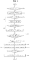
- FIG. 3 is a flowchart illustrating a clutch control method for a vehicle according to another form of the present disclosure.
- FIG. 4 is a graph showing the clutch control method for a vehicle in one form of the present disclosure.
- a clutch system of a vehicle is configured such that, when a controller CLR receives the operation state of a shift lever TL and the operation state of a clutch pedal CP and controls a hydraulic-driving actuator PD to generate hydraulic pressure, the generated hydraulic pressure is transferred to a hydraulically driven actuator PP, which is mounted to a clutch CL, to drive the clutch CL.
- the controller CLR may be configured not to separately receive the operation state of the clutch pedal CP but to control the clutch CL during a shift operation by determining the travel conditions of the vehicle.
- the clutch CL is of a normally-closed type, which basically forms the state shown in FIG. 1 .
- the power from an engine is continuously input to a transmission through the clutch CL.
- the controller CLR drives the hydraulic-driving actuator PD so that a piston 3 in a pressure chamber 1 moves to the left on the basis of FIG. 2 .
- hydraulic pressure is generated in the oil in the pressure chamber 1 , and the hydraulic pressure is transferred to the hydraulically driven actuator PP through a pressure pipe 5 , thereby opening the clutch CL.
- the pressure chamber 1 communicates with a reservoir tank 7 , and the oil stored in the reservoir tank 7 enters the pressure chamber 1 and mixes with the oil in the pressure chamber 1 , thereby reducing the temperature of the oil in the pressure chamber 1 .
- a clutch control method for a vehicle includes: a step of increasing, by the controller CLR, a clutch torque to a refill execution torque at a predetermined first inclination when a predetermined first reference time period has elapsed in a micro-slip state of the clutch (S 10 ), a step of increasing, by the controller CLR, the clutch torque to a refill torque at a predetermined second inclination to initiate refilling of the pressure chamber 1 of the hydraulic-driving actuator PD with the oil in the reservoir tank 7 when the clutch torque reaches the refill execution torque (S 20 ), and a step of maintaining the clutch torque at the refill torque during a predetermined second reference time period (S 30 ).
- the controller CLR increases the clutch torque in order to refill the pressure chamber 1 with the oil in the reservoir tank 7 , thereby reducing the temperature of the oil in the pressure chamber 1 , thus reducing or minimizing variation in the clutch characteristics according to an increase in the temperature of the oil.
- the controller CLR is capable of more accurately and stably controlling the clutch CL.
- the controller CLR determines the conditions under which micro-slip is executable. Upon determining that micro-slip is executable, the controller CLR creates the micro-slip state and learns the clutch characteristics during the first reference time period during which the micro-slip state is maintained.
- micro-slip is executable taking into consideration the state of the vehicle in which the engaged state of the clutch CL is capable of being stably maintained for a predetermined time period or longer, such as, for example, the state in which a shift operation is not being performed or the state in which the vehicle is not starting to move.
- the micro-slip state is a state in which slight slippage, which is about 20 RPM, occurs in the clutch CL.
- the slippage is a speed difference between opposite sides of the clutch CL, i.e. between the engine and the input shaft of the transmission.
- the engine torque in this state is substantially the same as the torque transferred through the clutch.
- learning is performed in a manner of forming the micro-slip state of the clutch, taking the engine torque in this state as the clutch torque, and applying the stroke of the actuator that forms the micro-slip state to the clutch torque.
- the stroke of the actuator may be considered to be the stroke of the piston 3 shown in FIGS. 1 and 2 .
- the first reference time period may be set in consideration of the time period during which learning of the clutch characteristics is possible through a large number of experiments.
- the first reference time period may be set to 30 ms.
- the refill execution torque is set to a clutch torque value that corresponds to a position of the piston 3 , which generates pressure in the pressure chamber 1 of the hydraulic-driving actuator PD, just before the pressure chamber 1 communicates with the reservoir tank 7 .
- the refill torque is set to a clutch torque value that corresponds to a position of the piston 3 at which the piston 3 fully opens a passage that communicates with the reservoir tank 7 .
- the clutch torque value that corresponds to the position of the piston 3 at which the piston 3 completely opens an orifice 9 which is a passage connecting the pressure chamber 1 to the reservoir tank 7 , is equivalent to the refill torque.
- the clutch torque value that corresponds to the position of the piston 3 just before opening the orifice 9 which is a position slightly shifted to the left from that shown in FIG. 1 , is equivalent to the refill execution torque.
- the first inclination at which the clutch torque is increased is set to be less than the second inclination, and the second inclination is set to a maximum possible value.
- the speed at which the clutch torque is increased is relatively high. This is for quick execution of the control process of the present disclosure in order to prepare for the situation in which the driver operates the clutch pedal CP again.
- the piston 3 is returned at the second inclination, which is greater than the first inclination, in order to more smoothly refill the pressure chamber 1 with the oil in the reservoir tank 7 .
- the second inclination may be set to a value for returning the piston 3 at the maximum possible speed of the hydraulic-driving actuator PD.
- the second reference time period may be set based on the time period during which the temperature of the oil in the pressure chamber is sufficiently reduced by the above-described refill operation.
- the second reference time period may be set to 100 ms.
- the clutch control method further includes: a step of reducing, by the controller CLR, the clutch torque so that the clutch again forms the micro-slip state after the clutch torque is maintained at the refill torque during the second reference time period (S 40 ), and a step of confirming, by the controller CLR, the clutch characteristics learned during the first reference time period while maintaining the micro-slip state after reducing the clutch torque (S 50 ).
- the controller CLR determines whether the clutch characteristics learned during the first reference time period are appropriate through the above-described steps.
- the clutch control method further includes: a step of increasing, by the controller CLR, the clutch torque again to the refill execution torque at the first inclination after confirming the learned clutch characteristics (S 60 ), and a step of increasing, by the controller CLR, the clutch torque to the refill torque at the second inclination (S 70 ).
- the controller CLR Upon determining that the learned clutch characteristics are appropriate, the controller CLR again increases the clutch torque to the refill torque to continuously maintain the completely engaged state of the clutch CL until a separate situation, such as operation of the clutch pedal CP on the part of the driver, occurs, and terminates the control process of the present disclosure.
- the controller CLR Upon determining that the clutch characteristics learned during the first reference time period are not appropriate, the controller CLR maintains the second micro-slip state for a longer time period, and again learns the clutch characteristics.
- a pressure chamber which is provided in the actuator in order to generate hydraulic pressure, is made to communicate with a reservoir tank so that the pressure chamber is refilled with the oil in the reservoir tank. Accordingly, variation in the physical characteristics of the oil, such as an increase in the temperature of the oil, may be reduced or minimized, and thus it is possible to continuously maintain and secure more accurate control of the clutch.
Abstract
Description
Claims (7)
Applications Claiming Priority (2)
| Application Number | Priority Date | Filing Date | Title |
|---|---|---|---|
| KR1020200047836A KR20210130284A (en) | 2020-04-21 | 2020-04-21 | Clutch control method for vehicle |
| KR10-2020-0047836 | 2020-04-21 |
Publications (2)
| Publication Number | Publication Date |
|---|---|
| US20210324925A1 US20210324925A1 (en) | 2021-10-21 |
| US11221049B2 true US11221049B2 (en) | 2022-01-11 |
Family
ID=78082660
Family Applications (1)
| Application Number | Title | Priority Date | Filing Date |
|---|---|---|---|
| US17/019,758 Active US11221049B2 (en) | 2020-04-21 | 2020-09-14 | Clutch control method for vehicle |
Country Status (3)
| Country | Link |
|---|---|
| US (1) | US11221049B2 (en) |
| KR (1) | KR20210130284A (en) |
| CN (1) | CN113531115A (en) |
Families Citing this family (2)
| Publication number | Priority date | Publication date | Assignee | Title |
|---|---|---|---|---|
| CN111288043B (en) * | 2020-02-19 | 2022-09-30 | 中国第一汽车股份有限公司 | Clutch execution piston clamping stagnation detection method and device |
| CN114151468B (en) * | 2021-12-01 | 2024-03-26 | 中国第一汽车股份有限公司 | Clutch hysteresis model construction method, control method, device, equipment and medium |
Citations (1)
| Publication number | Priority date | Publication date | Assignee | Title |
|---|---|---|---|---|
| KR100793896B1 (en) | 2006-12-06 | 2008-01-15 | 현대자동차주식회사 | Method for clutch release learn control of transmission |
-
2020
- 2020-04-21 KR KR1020200047836A patent/KR20210130284A/en unknown
- 2020-09-14 US US17/019,758 patent/US11221049B2/en active Active
- 2020-09-17 CN CN202010978155.8A patent/CN113531115A/en active Pending
Patent Citations (1)
| Publication number | Priority date | Publication date | Assignee | Title |
|---|---|---|---|---|
| KR100793896B1 (en) | 2006-12-06 | 2008-01-15 | 현대자동차주식회사 | Method for clutch release learn control of transmission |
Also Published As
| Publication number | Publication date |
|---|---|
| KR20210130284A (en) | 2021-11-01 |
| CN113531115A (en) | 2021-10-22 |
| US20210324925A1 (en) | 2021-10-21 |
Similar Documents
| Publication | Publication Date | Title |
|---|---|---|
| US11221049B2 (en) | Clutch control method for vehicle | |
| US7150333B2 (en) | Vehicle control apparatus and method | |
| US20120028759A1 (en) | Vehicular power transmission control apparatus | |
| JPS6011756A (en) | Automatic clutch control system | |
| EP2835552B1 (en) | Device for controlling start clutches for vehicles | |
| JP4603600B2 (en) | Hydraulic control device for automatic transmission | |
| WO2008062750A1 (en) | Half-clutch point learning device for wet multiple disk clutch | |
| US20140332333A1 (en) | Device for controlling automatic transmission | |
| US10260577B2 (en) | Vehicle launch control method | |
| JP2006123642A (en) | Driving device for hybrid vehicle, its control method and controller | |
| CN104100506A (en) | Electric oil pump control system and control method for automatic transmission | |
| KR102091226B1 (en) | Method for controlling hybrid powertrain, hybrid powertrain, and vehicle including such hybrid powertrain | |
| CN104455382A (en) | System and method for controlling a dry dual clutch transmission of a vehicle | |
| CN112969863B (en) | Method and control device for operating a drive train of a vehicle | |
| JP4852613B2 (en) | Clutch control method and control device | |
| JP2005133782A (en) | Lock up clutch control device | |
| CN106594113A (en) | Method for controlling clutch of vehicle | |
| US6533703B2 (en) | Method for controlling a motor vehicle drive and a motor vehicle drive that is controlled using the method | |
| US11668392B2 (en) | Method and control unit for freeing a vehicle by rocking | |
| CN109070894B (en) | Method for operating a drive train of a motor vehicle and drive train module of such a motor vehicle | |
| JP2738202B2 (en) | Shift control method for automatic transmission for vehicle | |
| JP2018189149A (en) | Clutch control apparatus | |
| KR20180122498A (en) | Control method of clutch for vehicle | |
| JP6278080B1 (en) | Shift control device for automatic transmission | |
| US11680613B2 (en) | Method for adapting a biting point of a hydraulically actuated hybrid disengaging clutch |
Legal Events
| Date | Code | Title | Description |
|---|---|---|---|
| FEPP | Fee payment procedure |
Free format text: ENTITY STATUS SET TO UNDISCOUNTED (ORIGINAL EVENT CODE: BIG.); ENTITY STATUS OF PATENT OWNER: LARGE ENTITY |
|
| AS | Assignment |
Owner name: KIA MOTORS CORPORATION, KOREA, REPUBLIC OF Free format text: ASSIGNMENT OF ASSIGNORS INTEREST;ASSIGNOR:CHO, SUNG HYUN;REEL/FRAME:053923/0207 Effective date: 20200805 Owner name: HYUNDAI MOTOR COMPANY, KOREA, REPUBLIC OF Free format text: ASSIGNMENT OF ASSIGNORS INTEREST;ASSIGNOR:CHO, SUNG HYUN;REEL/FRAME:053923/0207 Effective date: 20200805 |
|
| STPP | Information on status: patent application and granting procedure in general |
Free format text: NOTICE OF ALLOWANCE MAILED -- APPLICATION RECEIVED IN OFFICE OF PUBLICATIONS |
|
| STPP | Information on status: patent application and granting procedure in general |
Free format text: PUBLICATIONS -- ISSUE FEE PAYMENT RECEIVED |
|
| STPP | Information on status: patent application and granting procedure in general |
Free format text: PUBLICATIONS -- ISSUE FEE PAYMENT VERIFIED |
|
| STCF | Information on status: patent grant |
Free format text: PATENTED CASE |