US11221048B2 - Unidirectional rotary bearing - Google Patents
Unidirectional rotary bearing Download PDFInfo
- Publication number
- US11221048B2 US11221048B2 US16/891,387 US202016891387A US11221048B2 US 11221048 B2 US11221048 B2 US 11221048B2 US 202016891387 A US202016891387 A US 202016891387A US 11221048 B2 US11221048 B2 US 11221048B2
- Authority
- US
- United States
- Prior art keywords
- rotatable driving
- segment
- bearing body
- homing
- bearing
- Prior art date
- Legal status (The legal status is an assumption and is not a legal conclusion. Google has not performed a legal analysis and makes no representation as to the accuracy of the status listed.)
- Expired - Fee Related
Links
Images


Classifications
-
- F—MECHANICAL ENGINEERING; LIGHTING; HEATING; WEAPONS; BLASTING
- F16—ENGINEERING ELEMENTS AND UNITS; GENERAL MEASURES FOR PRODUCING AND MAINTAINING EFFECTIVE FUNCTIONING OF MACHINES OR INSTALLATIONS; THERMAL INSULATION IN GENERAL
- F16C—SHAFTS; FLEXIBLE SHAFTS; ELEMENTS OR CRANKSHAFT MECHANISMS; ROTARY BODIES OTHER THAN GEARING ELEMENTS; BEARINGS
- F16C19/00—Bearings with rolling contact, for exclusively rotary movement
- F16C19/22—Bearings with rolling contact, for exclusively rotary movement with bearing rollers essentially of the same size in one or more circular rows, e.g. needle bearings
- F16C19/24—Bearings with rolling contact, for exclusively rotary movement with bearing rollers essentially of the same size in one or more circular rows, e.g. needle bearings for radial load mainly
- F16C19/26—Bearings with rolling contact, for exclusively rotary movement with bearing rollers essentially of the same size in one or more circular rows, e.g. needle bearings for radial load mainly with a single row of rollers
-
- F—MECHANICAL ENGINEERING; LIGHTING; HEATING; WEAPONS; BLASTING
- F16—ENGINEERING ELEMENTS AND UNITS; GENERAL MEASURES FOR PRODUCING AND MAINTAINING EFFECTIVE FUNCTIONING OF MACHINES OR INSTALLATIONS; THERMAL INSULATION IN GENERAL
- F16D—COUPLINGS FOR TRANSMITTING ROTATION; CLUTCHES; BRAKES
- F16D41/00—Freewheels or freewheel clutches
- F16D41/06—Freewheels or freewheel clutches with intermediate wedging coupling members between an inner and an outer surface
- F16D41/08—Freewheels or freewheel clutches with intermediate wedging coupling members between an inner and an outer surface with provision for altering the freewheeling action
-
- F—MECHANICAL ENGINEERING; LIGHTING; HEATING; WEAPONS; BLASTING
- F16—ENGINEERING ELEMENTS AND UNITS; GENERAL MEASURES FOR PRODUCING AND MAINTAINING EFFECTIVE FUNCTIONING OF MACHINES OR INSTALLATIONS; THERMAL INSULATION IN GENERAL
- F16C—SHAFTS; FLEXIBLE SHAFTS; ELEMENTS OR CRANKSHAFT MECHANISMS; ROTARY BODIES OTHER THAN GEARING ELEMENTS; BEARINGS
- F16C33/00—Parts of bearings; Special methods for making bearings or parts thereof
- F16C33/30—Parts of ball or roller bearings
- F16C33/306—Means to synchronise movements
-
- F—MECHANICAL ENGINEERING; LIGHTING; HEATING; WEAPONS; BLASTING
- F16—ENGINEERING ELEMENTS AND UNITS; GENERAL MEASURES FOR PRODUCING AND MAINTAINING EFFECTIVE FUNCTIONING OF MACHINES OR INSTALLATIONS; THERMAL INSULATION IN GENERAL
- F16D—COUPLINGS FOR TRANSMITTING ROTATION; CLUTCHES; BRAKES
- F16D41/00—Freewheels or freewheel clutches
- F16D41/06—Freewheels or freewheel clutches with intermediate wedging coupling members between an inner and an outer surface
- F16D41/064—Freewheels or freewheel clutches with intermediate wedging coupling members between an inner and an outer surface the intermediate members wedging by rolling and having a circular cross-section, e.g. balls
- F16D41/066—Freewheels or freewheel clutches with intermediate wedging coupling members between an inner and an outer surface the intermediate members wedging by rolling and having a circular cross-section, e.g. balls all members having the same size and only one of the two surfaces being cylindrical
- F16D41/067—Freewheels or freewheel clutches with intermediate wedging coupling members between an inner and an outer surface the intermediate members wedging by rolling and having a circular cross-section, e.g. balls all members having the same size and only one of the two surfaces being cylindrical and the members being distributed by a separate cage encircling the axis of rotation
-
- F—MECHANICAL ENGINEERING; LIGHTING; HEATING; WEAPONS; BLASTING
- F16—ENGINEERING ELEMENTS AND UNITS; GENERAL MEASURES FOR PRODUCING AND MAINTAINING EFFECTIVE FUNCTIONING OF MACHINES OR INSTALLATIONS; THERMAL INSULATION IN GENERAL
- F16C—SHAFTS; FLEXIBLE SHAFTS; ELEMENTS OR CRANKSHAFT MECHANISMS; ROTARY BODIES OTHER THAN GEARING ELEMENTS; BEARINGS
- F16C2326/00—Articles relating to transporting
- F16C2326/20—Land vehicles
- F16C2326/28—Bicycle propulsion, e.g. crankshaft and its support
Definitions
- the present invention relates to a rotary bearing, and more particularly to a unidirectional rotary bearing which provides transmission torque in a unidirectional direction by using power machinery so as to reduce frictional resistance as the unidirectional rotary bearing rotates.
- Conventional unidirectional rotary bearings contain three kinds of a ratchet bearing 60 , an elastic friction bearing 70 , and a magnetic friction bearing 80 .
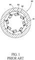
- the ratchet bearing 60 contains a connection loop 61 on which multiple springs 62 are arranged, multiple ratchet teeth 63 correspond to the multiple springs 62 respectively and pushed to multiple ratchets 64 individually so that when the connection loop 61 rotates in one direction, the multiple ratchet teeth 63 retain with and drive the multiple ratchets 64 respectively; and when the connection loop 61 rotates in another direction, the multiple ratchet teeth 63 press the multiple springs 62 to move on the multiple ratchets 64 individually and to rotate idly.
- the ratchet bearing 60 rotates idly, the multiple ratchet teeth 63 are pushed by the multiple springs 62 to move to the multiple ratchets 64 , thus producing moving resistance.
- the elastic friction bearing 70 contains a bearing ring 71 on which multiple springs 72 are arranged and push multiple friction elements 73 to a connection loop 74 , hence when the elastic friction bearing 70 rotates in one direction, the multiple friction elements 73 movably press the multiple springs 72 and rotate idly by mating with the connection loop 74 ; when the elastic friction bearing 70 rotates in another direction, the multiple friction elements 73 rotate reversely and are pushed outwardly by the multiple springs 72 , and the multiple friction elements 73 retain with the bearing ring 71 and the connection loop 74 .
- the elastic friction bearing 70 idly rotates between the multiple friction elements 73 and the connection loop 74 , and the multiple friction elements 73 are pushed by the multiple springs 72 to be against the connection loop 74 and the bearing ring 71 .
- an idle resistance of the unidirectional rotary bearing increases, for example, when the unidirectional rotary bearing is secured on the bicycle, the idle resistance greatly reduces a slide distance as not stepping the bicycle, thus decreasing jumping or rolling resistance and saving riding force.
- the magnetic friction bearing 80 contains a bearing ring 81 on which multiple locking slots 82 are defined, each of the multiple locking slots 82 has a magnet 83 accommodated on a bottom thereof, and a friction element 84 is fixed in each locking slot 82 and is magnetically attracted by the magnet 83 , wherein each magnet 83 magnetically attracts the friction element 84 to move to a connection loop 85 .
- the friction element 84 slides on each magnet 83 and rotates idly by mating with the connection loop 85 .
- the friction element 84 When the bearing ring 81 rotates in another direction, the friction element 84 is magnetically attracted by each magnet 83 to move back to an original position, and the friction element 84 retains with and drives the bearing ring 81 and the connection loop 85 to rotate. As rotating idly, the friction element 84 produces a resistance to the connection loop 85 , and the resistance is a magnetic attraction resistance when each magnet 83 magnetically attracts the friction element 84 .
- connection loop 61 of the ratchet bearing 60 actuates each ratchet tooth 63 of each ratchet 64 by using each spring 62 .
- the connection loop 74 of the elastic friction bearing 70 drives each friction element 73 of the bearing ring 71 by using each spring 72 .
- the connection loop 85 of the magnetic friction bearing 80 drives each friction element 84 of the bearing ring 81 by using each magnet 82 .
- the resistance decreases, wherein the number of the multiple springs 62 , 72 or the multiple magnets 83 correspond to those of the multiple ratchet teeth 63 or the multiple friction elements 73 , 84 , and the number of the multiple ratchet teeth 63 or the multiple friction elements 84 are related to torque, i.e., the higher the numbers are, the stronger torque is, but the torque is lowered in order to decrease the frictional resistance of idle rotation.
- a sealed high capacity overrunning roller clutch is disclosed in the US Publication No. 20110168119.
- a cage 52 is fixed and actuates multiple rollers 50 .
- the roller clutch is complicated and is assembled difficultly at a high cost.
- the cage 52 and the multiple rollers 50 operate in a same accommodation space to reduce a number of the multiple rollers 50 .
- the accommodation space receives a plurality of alignment blocks 112 and accordion springs 59 , thus reducing the number of the multiple rollers 50 greatly. Because the number of the multiple rollers 50 influences a torque of a torque through clutch 10 , the less the multiple rollers are, the smaller the torque withstands.
- the present invention has arisen to mitigate and/or obviate the afore-described disadvantages.
- the primary objective of the present invention is to provide a unidirectional rotary bearing which contains a respective rotatable driving ring of two rotatable driving rings received in a respective circular groove of each peripheral surface of two sides of a bearing body and configured to drive multiple rollers to revolve, such that the multiple rollers rotate on the internal surface of the bearing body so as to enhance the number of the multiple rollers to a maximum value, wherein a number of the multiple rollers influences a torque of the unidirectional rotary bearing, for example, the more rollers is, the stronger torque of the unidirectional rotary bearing withstands.
- a unidirectional rotary bearing contained by the present invention contains a bearing body, multiple rollers, two rotatable driving rings, and at least two homing springs.
- the bearing body includes an internal surface and two peripheral surfaces, wherein the internal surface has multiple receiving grooves separately arranged thereon and matching with the multiple rollers respectively, each of the multiple receiving grooves has an engagement segment and a disengagement segment, a depth of the engagement segment is less than a depth of the disengagement segment, and two sides of bearing body further includes two circular grooves.
- the multiple rollers are accommodated in the multiple receiving grooves of the bearing body respectively, and each of the multiple rollers moves between the engagement segment and the disengagement segment of the receiving groove, wherein each roller is columnar and has a diameter which is more than the depth of the engagement segment of each receiving groove of the bearing body and is less than the depth of the disengagement segment of each receiving groove of the bearing body, and each roller has two drive extensions extending outwardly from two opposite ends thereof respectively.
- the two rotatable driving rings are housed in two circular grooves of the two peripheral surfaces of the bearing body individually, and an angle is produced between the two rotatable driving rings, wherein each rotatable driving ring has multiple apertures, each of the multiple apertures is more than each of the two drive extensions and is less than the diameter of each roller, and each drive extension is accommodated in each of the multiple apertures so that when each rotatable driving ring produces an angular rotation, each roller is driven synchronously.
- a number of the at least two homing springs are less than that of the multiple rollers so as to push the two rotatable driving rings to the engagement segment from the disengagement segment.
- FIG. 1 is a cross-sectional view of a conventional ratchet bearing.
- FIG. 2 is a cross-sectional view of a conventional elastic friction bearing.
- FIG. 3 is a perspective view of a conventional magnetic friction bearing.
- FIG. 4 is a cross-sectional view of the conventional magnetic friction bearing.
- FIG. 5 is another cross-sectional view of the conventional magnetic friction bearing.
- FIG. 6 is a perspective view showing the assembly of a unidirectional rotary bearing in accordance with a preferred embodiment of the present invention.
- FIG. 7 is a perspective view showing the exploded components of the unidirectional rotary bearing in accordance with the preferred embodiment of the present invention.
- FIG. 8 is a perspective view showing the exploded components of a part of the unidirectional rotary bearing in accordance with the preferred embodiment of the present invention.
- FIG. 9 is a cross-sectional view showing the assembly of the unidirectional rotary bearing in accordance with the preferred embodiment of the present invention.
- FIG. 10 is a cross-sectional view showing the assembly of a part of the unidirectional rotary bearing in accordance with the preferred embodiment of the present invention.
- FIG. 11 is another cross-sectional view showing the assembly of the unidirectional rotary bearing in accordance with the preferred embodiment of the present invention.
- FIG. 12 is a cross-sectional view showing the operation of the unidirectional rotary bearing in accordance with the preferred embodiment of the present invention.
- FIG. 13 is another cross-sectional view showing the operation of the unidirectional rotary bearing in accordance with the preferred embodiment of the present invention.
- FIG. 14 is an amplified cross-sectional view showing the operation of a part of the unidirectional rotary bearing according to the preferred embodiment of the present invention.
- FIG. 15 is a perspective view showing the application of the unidirectional rotary bearing according to the preferred embodiment of the present invention.
- FIG. 16 is a cross-sectional view showing the application of the unidirectional rotary bearing according to the preferred embodiment of the present invention.
- FIG. 17 is another cross-sectional view showing the application of the unidirectional rotary bearing according to the preferred embodiment of the present invention.
- FIG. 18 is still another cross-sectional view showing the application of the unidirectional rotary bearing according to the preferred embodiment of the present invention.
- a unidirectional rotary bearing 1 in accordance with a preferred embodiment of the present invention comprises: a bearing body 10 , multiple rollers 20 , two rotatable driving rings 30 , at least two homing springs 40 , and two covers 50 .
- the bearing body 10 includes an internal surface 11 and two peripheral surfaces 12 , 13 , the internal surface 11 has multiple receiving grooves 111 separately defined on the internal surface 11 , configured to accommodate the multiple rollers 20 , and passing through the two peripheral surfaces 12 , 13 of the bearing body 10 , wherein a respective receiving groove 111 has an engagement segment 1111 and a disengagement segment 1112 , the engagement segment 1111 has an engaging depth h 1 , and the disengagement segment 1112 has a disengaging depth h 2 , wherein the engaging depth h 1 of the engagement segment 1111 is less than the disengaging depth h 2 of the disengagement segment 1112 .
- Each of the two peripheral surfaces 12 , 13 has a circular groove 14 formed thereon and has at least two homing caves 15 mating with the circular groove 14 , wherein a number of the at least two homing caves 15 corresponds to a number of the at least two homing springs 40 .
- a respective roller 20 is accommodated in the respective receiving groove 111 of the bearing body 10 and moves between the engagement segment 1111 and the disengagement segment 1112 , wherein the respective roller 20 is columnar and includes a diameter d 1 which is more than the engaging depth h 1 of the engagement segment 1111 of the respective receiving groove 111 of the bearing body 10 , the diameter d 1 of the respective roller 20 is less than the disengaging depth h 2 of the disengagement segment 1112 of the respective receiving groove 111 of the bearing body 10 , and the respective roller 20 includes two drive extensions 21 , the respective roller 20 has a respective drive extension 21 extends from a center of each of two ends thereof.
- a respective rotatable driving ring 30 is received in the respective circular groove 14 of each peripheral surface 12 or 13 of two sides of the bearing body 10 , and the two rotatable driving rings 30 are rotated at an angle X, wherein the respective rotatable driving ring 30 includes at least two returning plates 31 corresponding to a respective homing cave 15 , multiple apertures 32 formed around the respective rotatable driving ring 30 , and a respective aperture 32 corresponds to the respective receiving groove 111 , wherein a diameter of the respective aperture 32 is more than a diameter of the respective drive extension 21 , the diameter of the respective drive extension 21 is less than the diameter d 1 of the respective roller 20 , the respective drive extension 21 passes through the respective aperture 32 so that when the two rotatable driving rings 30 rotate at the angle X, the multiple rollers 20 are driven by the two rotatable driving rings 30 to move circumferentially, the angle X of the two rotatable driving rings 30 is a distance where the respective roller 20 moves between the engagement segment 1111 and the
- the number of the at least two homing springs 40 are fewer than a number of the multiple rollers 20 , wherein a respective homing spring 40 is accommodated in the respective homing cave 15 , a first end of the respective homing spring 40 abuts against the bearing body 10 , and a second end of the respective homing spring 40 contacts with a returning plate 31 so that the two rotatable driving rings 30 are pushed from the disengagement segment 1112 to the engagement segment 1111 , and the multiple rollers 20 are controlled by the at least two homing springs 40 to rotate at the angle X between the engagement segment 1111 and the disengagement segment 1112 .
- the two covers 50 are fixed on the two peripheral surfaces 12 , 13 of the bearing body 10 to limit the two rotatable driving rings 30 and the multiple rollers 20 , such that the two rotatable driving rings 30 and the multiple rollers 20 are not fallen out, and the two rotatable driving rings 30 rotate at the angle X smoothly.
- connection loop 100 When driving the multiple rollers 20 to rotate synchronously, as illustrated in FIG. 12 , a connection loop 100 is inserted through a center of the bearing body 10 to contact with the respective roller 20 .
- the connection loop 100 rotates clockwise, the respective roller 20 is driven to revolve clockwise and to push the two rotatable driving rings 30 to rotate synchronously. Since the two rotatable driving rings 30 are driven by the respective roller 20 , when one roller 20 rotates, the other rollers 20 revolves synchronously, wherein the respective roller 20 and the two rotatable driving rings 30 are pushed to rotate at the angle X so that the respective roller 20 moves from the disengagement segment 1112 to the engagement segment 1111 . In the meantime, the respective roller 20 engages with the connection loop 100 and the bearing body 10 so that the connection loop 100 rotates synchronously with the bearing body 10 , and the respective homing spring 40 pushes the two rotatable driving rings 30 .
- connection loop 100 When the connection loop 100 does not rotate, revolves counterclockwise or a rotation speed of the connection loop 100 is slower than a rotation speed of the bearing body 10 , as shown in FIGS. 13 and 14 , the bearing body 10 presses the respective homing spring 40 so that the connection loop 100 rotates counterclockwise to push the respective roller 20 , the respective roller 20 rotates counterclockwise to push the two rotatable driving rings 30 to revolve counterclockwise, hence the respective roller 20 is pushed by the two rotatable driving rings 30 to move from the engagement segment 1111 to the disengagement segment 1112 .
- a clearance 1113 is defined between the respective roller 20 and the bearing body 10 or the connection loop 100 until the connection loop 100 and the bearing body 10 do not rotate, and the respective roller 20 rotates idly in the respective aperture 32 , wherein the respective roller 20 pushes the two rotatable driving rings 30 to revolve counterclockwise at the angle X.
- the unidirectional rotary bearing 1 is disposed on a hub 2 mounted between a rear wheel and a freewheel 3 (which is connected with the connection loop 100 ), the hub 2 includes a center shaft 101 fixed with a bicycle frame 102 , and the unidirectional rotary bearing 1 is configured to drive the freewheel 3 to revolve synchronously or asynchronously.
- the unidirectional rotary bearing 1 of the present invention contains advantages as follows:
- the respective rotatable driving ring 30 is received in the respective circular groove 14 of each peripheral surface 12 or 13 of the bearing body 10 and is configured to drive the multiple rollers 20 to revolve, such that the multiple rollers 20 rotate on the internal surface 11 of the bearing body 10 so as to enhance the number of the multiple rollers 20 to a maximum torque value, wherein the number of the multiple rollers 20 influences a torque of the unidirectional rotary bearing 1 , for example, the more rollers 20 is, the stronger torque of the unidirectional rotary bearing 1 withstands.
- the unidirectional rotary bearing 1 actuates the two rotatable driving rings 30 by using less homing spring 40 , and two sides of the two rotatable driving rings 30 are actuated to drive the multiple rollers 20 to revolve synchronously, such that friction is decreased when the multiple rollers 20 is not driven synchronously and rotates idly.
- the number of the multiple rollers 20 is increased to enhance the torque, and the two rotatable driving rings 30 actuate the multiple rollers 20 to reduce the friction when the multiple rollers 20 rotate idly.
Landscapes
- Engineering & Computer Science (AREA)
- General Engineering & Computer Science (AREA)
- Mechanical Engineering (AREA)
- Rolling Contact Bearings (AREA)
Abstract
Description
Claims (2)
Priority Applications (1)
| Application Number | Priority Date | Filing Date | Title |
|---|---|---|---|
| US16/891,387 US11221048B2 (en) | 2017-11-24 | 2020-06-03 | Unidirectional rotary bearing |
Applications Claiming Priority (2)
| Application Number | Priority Date | Filing Date | Title |
|---|---|---|---|
| US15/821,938 US20190162257A1 (en) | 2017-11-24 | 2017-11-24 | Unidirectional Rotary Brake |
| US16/891,387 US11221048B2 (en) | 2017-11-24 | 2020-06-03 | Unidirectional rotary bearing |
Related Parent Applications (1)
| Application Number | Title | Priority Date | Filing Date |
|---|---|---|---|
| US15/821,938 Continuation-In-Part US20190162257A1 (en) | 2017-11-24 | 2017-11-24 | Unidirectional Rotary Brake |
Publications (2)
| Publication Number | Publication Date |
|---|---|
| US20200291992A1 US20200291992A1 (en) | 2020-09-17 |
| US11221048B2 true US11221048B2 (en) | 2022-01-11 |
Family
ID=72425077
Family Applications (1)
| Application Number | Title | Priority Date | Filing Date |
|---|---|---|---|
| US16/891,387 Expired - Fee Related US11221048B2 (en) | 2017-11-24 | 2020-06-03 | Unidirectional rotary bearing |
Country Status (1)
| Country | Link |
|---|---|
| US (1) | US11221048B2 (en) |
Citations (10)
| Publication number | Priority date | Publication date | Assignee | Title |
|---|---|---|---|---|
| US2613776A (en) | 1946-04-08 | 1952-10-14 | Nat Machinery Co | Feed clutch for cold headers |
| GB953466A (en) | 1960-07-19 | 1964-03-25 | Borg Warner | Improvements in or relating to one-way engaging devices |
| US3236337A (en) | 1963-05-17 | 1966-02-22 | Joseph A Marland | One-way backstop |
| US3994377A (en) | 1974-04-05 | 1976-11-30 | The Torrington Company | Overrunning clutch retainer and roller assembly |
| US4770279A (en) | 1986-03-28 | 1988-09-13 | Nippo Sangyo Kabushiki Kaisha Co Ltd | One-way clutch |
| US6796414B2 (en) * | 2001-07-19 | 2004-09-28 | Tesman International Inc. | High capacity one-way clutch assembly |
| US20080179156A1 (en) | 2005-04-07 | 2008-07-31 | Donghwan Byun | Reverse Input Prevent Clutch Bearing Assembly |
| US20110168119A1 (en) | 2008-09-15 | 2011-07-14 | Magna Powertrain Inc. | Sealed high capacity overrunning roller clutch |
| DE102010052922A1 (en) * | 2010-11-30 | 2012-05-31 | Schaeffler Technologies Gmbh & Co. Kg | Roller freewheel used for crank continuous variable transmission for drive train of motor vehicle, has pinch rollers that are rotationally fixed to cage and biased relative to clamping ramps in circumferential direction |
| US8251195B2 (en) | 2010-03-29 | 2012-08-28 | Hon Hai Precision Industry Co., Ltd. | Bearing |
-
2020
- 2020-06-03 US US16/891,387 patent/US11221048B2/en not_active Expired - Fee Related
Patent Citations (10)
| Publication number | Priority date | Publication date | Assignee | Title |
|---|---|---|---|---|
| US2613776A (en) | 1946-04-08 | 1952-10-14 | Nat Machinery Co | Feed clutch for cold headers |
| GB953466A (en) | 1960-07-19 | 1964-03-25 | Borg Warner | Improvements in or relating to one-way engaging devices |
| US3236337A (en) | 1963-05-17 | 1966-02-22 | Joseph A Marland | One-way backstop |
| US3994377A (en) | 1974-04-05 | 1976-11-30 | The Torrington Company | Overrunning clutch retainer and roller assembly |
| US4770279A (en) | 1986-03-28 | 1988-09-13 | Nippo Sangyo Kabushiki Kaisha Co Ltd | One-way clutch |
| US6796414B2 (en) * | 2001-07-19 | 2004-09-28 | Tesman International Inc. | High capacity one-way clutch assembly |
| US20080179156A1 (en) | 2005-04-07 | 2008-07-31 | Donghwan Byun | Reverse Input Prevent Clutch Bearing Assembly |
| US20110168119A1 (en) | 2008-09-15 | 2011-07-14 | Magna Powertrain Inc. | Sealed high capacity overrunning roller clutch |
| US8251195B2 (en) | 2010-03-29 | 2012-08-28 | Hon Hai Precision Industry Co., Ltd. | Bearing |
| DE102010052922A1 (en) * | 2010-11-30 | 2012-05-31 | Schaeffler Technologies Gmbh & Co. Kg | Roller freewheel used for crank continuous variable transmission for drive train of motor vehicle, has pinch rollers that are rotationally fixed to cage and biased relative to clamping ramps in circumferential direction |
Non-Patent Citations (1)
| Title |
|---|
| Machine translation of DE102010052922. * |
Also Published As
| Publication number | Publication date |
|---|---|
| US20200291992A1 (en) | 2020-09-17 |
Similar Documents
| Publication | Publication Date | Title |
|---|---|---|
| US4770279A (en) | One-way clutch | |
| US20210155038A1 (en) | Bicycle hub structure | |
| EP2848428A1 (en) | Driving device for a hub | |
| US8833536B2 (en) | Ratchet mechanism for bicycle hub | |
| US20170204917A1 (en) | One-Way Clutch With Electro-Magnetic Solenoid | |
| US20190331170A1 (en) | Gear power transmitting mechanism | |
| WO2018099205A1 (en) | Double-ratchet type one-way clutch | |
| EP2599643B1 (en) | Ratchet hub | |
| US11221048B2 (en) | Unidirectional rotary bearing | |
| US20120012434A1 (en) | Electromagnetic clutch | |
| CN102086910B (en) | Bidirectional output unidirectional clutch mechanism | |
| US20190162257A1 (en) | Unidirectional Rotary Brake | |
| EP2529949A1 (en) | Ratchet mechanism for bicycle hub | |
| US20130092495A1 (en) | Hub assembly with the ratchet member movable in two directions | |
| US11993343B1 (en) | Transmission structure of hub motor | |
| US20020050430A1 (en) | Clutch device | |
| US11904633B2 (en) | Freehub of bicycle | |
| US20180100555A1 (en) | Unidirectional Rotating Brake | |
| EP2770224B1 (en) | Driving system for bicycle hub | |
| EP1205682A2 (en) | Speed controlled freewheel clutch device | |
| CN215096785U (en) | Bicycle hub ratchet structure | |
| US5896967A (en) | One-way clutch | |
| CN112644220A (en) | Bicycle hub structure | |
| TWI712516B (en) | Bicycle hub structure | |
| EP2594412B1 (en) | Hub assembly with the ratchet member movable in two directions |
Legal Events
| Date | Code | Title | Description |
|---|---|---|---|
| AS | Assignment |
Owner name: TAI-WORLD MFG. CO., LTD., TAIWAN Free format text: ASSIGNMENT OF ASSIGNORS INTEREST;ASSIGNOR:SHIH, SEN-TIEN;REEL/FRAME:052823/0285 Effective date: 20200529 |
|
| FEPP | Fee payment procedure |
Free format text: ENTITY STATUS SET TO UNDISCOUNTED (ORIGINAL EVENT CODE: BIG.); ENTITY STATUS OF PATENT OWNER: SMALL ENTITY |
|
| FEPP | Fee payment procedure |
Free format text: ENTITY STATUS SET TO SMALL (ORIGINAL EVENT CODE: SMAL); ENTITY STATUS OF PATENT OWNER: SMALL ENTITY |
|
| STPP | Information on status: patent application and granting procedure in general |
Free format text: DOCKETED NEW CASE - READY FOR EXAMINATION |
|
| STPP | Information on status: patent application and granting procedure in general |
Free format text: NON FINAL ACTION MAILED |
|
| STPP | Information on status: patent application and granting procedure in general |
Free format text: RESPONSE TO NON-FINAL OFFICE ACTION ENTERED AND FORWARDED TO EXAMINER |
|
| STPP | Information on status: patent application and granting procedure in general |
Free format text: NOTICE OF ALLOWANCE MAILED -- APPLICATION RECEIVED IN OFFICE OF PUBLICATIONS |
|
| STPP | Information on status: patent application and granting procedure in general |
Free format text: PUBLICATIONS -- ISSUE FEE PAYMENT VERIFIED |
|
| STCF | Information on status: patent grant |
Free format text: PATENTED CASE |
|
| FEPP | Fee payment procedure |
Free format text: MAINTENANCE FEE REMINDER MAILED (ORIGINAL EVENT CODE: REM.); ENTITY STATUS OF PATENT OWNER: SMALL ENTITY |