US11220066B2 - Spacer for use in precision bonding applications that provides enhanced shear strength - Google Patents
Spacer for use in precision bonding applications that provides enhanced shear strength Download PDFInfo
- Publication number
- US11220066B2 US11220066B2 US16/663,034 US201916663034A US11220066B2 US 11220066 B2 US11220066 B2 US 11220066B2 US 201916663034 A US201916663034 A US 201916663034A US 11220066 B2 US11220066 B2 US 11220066B2
- Authority
- US
- United States
- Prior art keywords
- spacer
- locator
- mating surface
- locator pin
- view
- Prior art date
- Legal status (The legal status is an assumption and is not a legal conclusion. Google has not performed a legal analysis and makes no representation as to the accuracy of the status listed.)
- Active, expires
Links
- 125000006850 spacer group Chemical group 0.000 title claims abstract description 229
- 230000013011 mating Effects 0.000 claims abstract description 84
- 239000012530 fluid Substances 0.000 claims description 12
- 230000033001 locomotion Effects 0.000 claims description 9
- 230000001788 irregular Effects 0.000 claims 2
- 238000005304 joining Methods 0.000 abstract description 22
- 230000008901 benefit Effects 0.000 abstract description 8
- 239000000853 adhesive Substances 0.000 description 37
- 230000001070 adhesive effect Effects 0.000 description 37
- 239000000463 material Substances 0.000 description 29
- 238000000034 method Methods 0.000 description 26
- 239000000758 substrate Substances 0.000 description 17
- 238000003466 welding Methods 0.000 description 11
- 230000008569 process Effects 0.000 description 9
- 239000004593 Epoxy Substances 0.000 description 7
- 239000003795 chemical substances by application Substances 0.000 description 7
- 238000000926 separation method Methods 0.000 description 7
- 239000004568 cement Substances 0.000 description 6
- 238000010276 construction Methods 0.000 description 6
- 238000004519 manufacturing process Methods 0.000 description 6
- 229920005749 polyurethane resin Polymers 0.000 description 6
- 238000013461 design Methods 0.000 description 5
- 239000000945 filler Substances 0.000 description 5
- 238000007789 sealing Methods 0.000 description 5
- 238000005260 corrosion Methods 0.000 description 3
- 230000007797 corrosion Effects 0.000 description 3
- 229920003023 plastic Polymers 0.000 description 3
- 239000004033 plastic Substances 0.000 description 3
- 238000004023 plastic welding Methods 0.000 description 3
- 238000005476 soldering Methods 0.000 description 3
- 229920001651 Cyanoacrylate Polymers 0.000 description 2
- 239000004822 Hot adhesive Substances 0.000 description 2
- CERQOIWHTDAKMF-UHFFFAOYSA-M Methacrylate Chemical compound CC(=C)C([O-])=O CERQOIWHTDAKMF-UHFFFAOYSA-M 0.000 description 2
- MWCLLHOVUTZFKS-UHFFFAOYSA-N Methyl cyanoacrylate Chemical compound COC(=O)C(=C)C#N MWCLLHOVUTZFKS-UHFFFAOYSA-N 0.000 description 2
- 239000004823 Reactive adhesive Substances 0.000 description 2
- NIXOWILDQLNWCW-UHFFFAOYSA-N acrylic acid group Chemical group C(C=C)(=O)O NIXOWILDQLNWCW-UHFFFAOYSA-N 0.000 description 2
- -1 cleaners Substances 0.000 description 2
- 229910001338 liquidmetal Inorganic materials 0.000 description 2
- 230000005389 magnetism Effects 0.000 description 2
- 229910052751 metal Inorganic materials 0.000 description 2
- 239000002184 metal Substances 0.000 description 2
- 238000000465 moulding Methods 0.000 description 2
- 230000002829 reductive effect Effects 0.000 description 2
- 239000000126 substance Substances 0.000 description 2
- WFKWXMTUELFFGS-UHFFFAOYSA-N tungsten Chemical compound [W] WFKWXMTUELFFGS-UHFFFAOYSA-N 0.000 description 2
- 229910052721 tungsten Inorganic materials 0.000 description 2
- 239000010937 tungsten Substances 0.000 description 2
- 229910000975 Carbon steel Inorganic materials 0.000 description 1
- VVQNEPGJFQJSBK-UHFFFAOYSA-N Methyl methacrylate Chemical compound COC(=O)C(C)=C VVQNEPGJFQJSBK-UHFFFAOYSA-N 0.000 description 1
- 230000002411 adverse Effects 0.000 description 1
- 230000000712 assembly Effects 0.000 description 1
- 238000000429 assembly Methods 0.000 description 1
- 239000010962 carbon steel Substances 0.000 description 1
- 239000000919 ceramic Substances 0.000 description 1
- 239000002131 composite material Substances 0.000 description 1
- 230000001010 compromised effect Effects 0.000 description 1
- 238000001816 cooling Methods 0.000 description 1
- 238000005553 drilling Methods 0.000 description 1
- 239000000975 dye Substances 0.000 description 1
- 230000000694 effects Effects 0.000 description 1
- 239000008393 encapsulating agent Substances 0.000 description 1
- 230000002708 enhancing effect Effects 0.000 description 1
- 238000005530 etching Methods 0.000 description 1
- 239000011152 fibreglass Substances 0.000 description 1
- 239000011521 glass Substances 0.000 description 1
- 238000001802 infusion Methods 0.000 description 1
- 238000007689 inspection Methods 0.000 description 1
- 230000002427 irreversible effect Effects 0.000 description 1
- 238000003475 lamination Methods 0.000 description 1
- 238000012423 maintenance Methods 0.000 description 1
- 230000014759 maintenance of location Effects 0.000 description 1
- 239000011159 matrix material Substances 0.000 description 1
- 230000007246 mechanism Effects 0.000 description 1
- 150000002739 metals Chemical class 0.000 description 1
- 238000012986 modification Methods 0.000 description 1
- 230000004048 modification Effects 0.000 description 1
- 239000003973 paint Substances 0.000 description 1
- 238000003825 pressing Methods 0.000 description 1
- 239000013615 primer Substances 0.000 description 1
- 239000002987 primer (paints) Substances 0.000 description 1
- 229920005989 resin Polymers 0.000 description 1
- 239000011347 resin Substances 0.000 description 1
- 230000002441 reversible effect Effects 0.000 description 1
- 239000000565 sealant Substances 0.000 description 1
- 239000004065 semiconductor Substances 0.000 description 1
- 238000004513 sizing Methods 0.000 description 1
- 239000002904 solvent Substances 0.000 description 1
- 238000003860 storage Methods 0.000 description 1
- 229920005992 thermoplastic resin Polymers 0.000 description 1
- 239000004634 thermosetting polymer Substances 0.000 description 1
- 230000000007 visual effect Effects 0.000 description 1
Images


Classifications
-
- B—PERFORMING OPERATIONS; TRANSPORTING
- B29—WORKING OF PLASTICS; WORKING OF SUBSTANCES IN A PLASTIC STATE IN GENERAL
- B29C—SHAPING OR JOINING OF PLASTICS; SHAPING OF MATERIAL IN A PLASTIC STATE, NOT OTHERWISE PROVIDED FOR; AFTER-TREATMENT OF THE SHAPED PRODUCTS, e.g. REPAIRING
- B29C66/00—General aspects of processes or apparatus for joining preformed parts
- B29C66/80—General aspects of machine operations or constructions and parts thereof
- B29C66/87—Auxiliary operations or devices
-
- F—MECHANICAL ENGINEERING; LIGHTING; HEATING; WEAPONS; BLASTING
- F16—ENGINEERING ELEMENTS AND UNITS; GENERAL MEASURES FOR PRODUCING AND MAINTAINING EFFECTIVE FUNCTIONING OF MACHINES OR INSTALLATIONS; THERMAL INSULATION IN GENERAL
- F16B—DEVICES FOR FASTENING OR SECURING CONSTRUCTIONAL ELEMENTS OR MACHINE PARTS TOGETHER, e.g. NAILS, BOLTS, CIRCLIPS, CLAMPS, CLIPS OR WEDGES; JOINTS OR JOINTING
- F16B5/00—Joining sheets or plates, e.g. panels, to one another or to strips or bars parallel to them
- F16B5/06—Joining sheets or plates, e.g. panels, to one another or to strips or bars parallel to them by means of clamps or clips
- F16B5/0607—Joining sheets or plates, e.g. panels, to one another or to strips or bars parallel to them by means of clamps or clips joining sheets or plates to each other
- F16B5/0621—Joining sheets or plates, e.g. panels, to one another or to strips or bars parallel to them by means of clamps or clips joining sheets or plates to each other in parallel relationship
- F16B5/065—Joining sheets or plates, e.g. panels, to one another or to strips or bars parallel to them by means of clamps or clips joining sheets or plates to each other in parallel relationship the plates being one on top of the other and distanced from each other, e.g. by using protrusions to keep contact and distance
-
- B—PERFORMING OPERATIONS; TRANSPORTING
- B29—WORKING OF PLASTICS; WORKING OF SUBSTANCES IN A PLASTIC STATE IN GENERAL
- B29C—SHAPING OR JOINING OF PLASTICS; SHAPING OF MATERIAL IN A PLASTIC STATE, NOT OTHERWISE PROVIDED FOR; AFTER-TREATMENT OF THE SHAPED PRODUCTS, e.g. REPAIRING
- B29C65/00—Joining or sealing of preformed parts, e.g. welding of plastics materials; Apparatus therefor
- B29C65/48—Joining or sealing of preformed parts, e.g. welding of plastics materials; Apparatus therefor using adhesives, i.e. using supplementary joining material; solvent bonding
-
- B—PERFORMING OPERATIONS; TRANSPORTING
- B29—WORKING OF PLASTICS; WORKING OF SUBSTANCES IN A PLASTIC STATE IN GENERAL
- B29C—SHAPING OR JOINING OF PLASTICS; SHAPING OF MATERIAL IN A PLASTIC STATE, NOT OTHERWISE PROVIDED FOR; AFTER-TREATMENT OF THE SHAPED PRODUCTS, e.g. REPAIRING
- B29C65/00—Joining or sealing of preformed parts, e.g. welding of plastics materials; Apparatus therefor
- B29C65/78—Means for handling the parts to be joined, e.g. for making containers or hollow articles, e.g. means for handling sheets, plates, web-like materials, tubular articles, hollow articles or elements to be joined therewith; Means for discharging the joined articles from the joining apparatus
- B29C65/7802—Positioning the parts to be joined, e.g. aligning, indexing or centring
- B29C65/782—Positioning the parts to be joined, e.g. aligning, indexing or centring by setting the gap between the parts to be joined
- B29C65/7823—Positioning the parts to be joined, e.g. aligning, indexing or centring by setting the gap between the parts to be joined by using distance pieces, i.e. by using spacers positioned between the parts to be joined and forming a part of the joint
- B29C65/7826—Positioning the parts to be joined, e.g. aligning, indexing or centring by setting the gap between the parts to be joined by using distance pieces, i.e. by using spacers positioned between the parts to be joined and forming a part of the joint said distance pieces being non-integral with the parts to be joined, e.g. particles
-
- F—MECHANICAL ENGINEERING; LIGHTING; HEATING; WEAPONS; BLASTING
- F16—ENGINEERING ELEMENTS AND UNITS; GENERAL MEASURES FOR PRODUCING AND MAINTAINING EFFECTIVE FUNCTIONING OF MACHINES OR INSTALLATIONS; THERMAL INSULATION IN GENERAL
- F16B—DEVICES FOR FASTENING OR SECURING CONSTRUCTIONAL ELEMENTS OR MACHINE PARTS TOGETHER, e.g. NAILS, BOLTS, CIRCLIPS, CLAMPS, CLIPS OR WEDGES; JOINTS OR JOINTING
- F16B11/00—Connecting constructional elements or machine parts by sticking or pressing them together, e.g. cold pressure welding
- F16B11/006—Connecting constructional elements or machine parts by sticking or pressing them together, e.g. cold pressure welding by gluing
-
- F—MECHANICAL ENGINEERING; LIGHTING; HEATING; WEAPONS; BLASTING
- F16—ENGINEERING ELEMENTS AND UNITS; GENERAL MEASURES FOR PRODUCING AND MAINTAINING EFFECTIVE FUNCTIONING OF MACHINES OR INSTALLATIONS; THERMAL INSULATION IN GENERAL
- F16B—DEVICES FOR FASTENING OR SECURING CONSTRUCTIONAL ELEMENTS OR MACHINE PARTS TOGETHER, e.g. NAILS, BOLTS, CIRCLIPS, CLAMPS, CLIPS OR WEDGES; JOINTS OR JOINTING
- F16B2200/00—Constructional details of connections not covered for in other groups of this subclass
- F16B2200/99—Fasteners with means for avoiding incorrect assembly or positioning
Definitions
- the present invention relates to spacers, and more specifically to spacers with locators used in a spacing and locating process.
- U.S. Pat. No. 8,040,638 for self-fixturing pivoting actuator by inventor Raymond, filed Jul. 27, 2006 and issued Oct. 18, 2011, describes a rotary actuator arm assembly for positioning a transducer over a data track of at least one rotating magnetic disk.
- the actuator includes self-contained spacers with semi-kinetic mounting features to accurately locate and secure a set of self-aligning components, thereby eliminating azimuth alignment problems created by conventional assembly procedures.
- the locator includes an elongated spacer element for determining the horizontal distance between a designated portion of the vehicle headlamp assembly and a forward portion of the vehicle hood.
- An upright spacer element is provided to position the elongated spacer element in the desired vertical position.
- the display apparatus includes a first substrate having an aperture layer formed thereon, a light guide for guiding light towards the aperture layer, a plurality of MEMS light modulators for modulating light passing through the aperture layer from the light guide, and a spacer substantially surrounding the light guide for keeping the light guide and the first substrate a predetermined distance apart from one another, thereby forming a gap between the first substrate and the light guide.
- the first substrate may have a control matrix formed thereon.
- U.S. Pat. No. 4,786,094 for mounting clip including break-away spacer element by inventor Barton et al., filed Oct. 6, 1987 and issued on Nov. 11, 1988, discloses a clip mounting structure which is attachable to a vehicle body without use of fixtures. This is done by initially providing the mounting structure with spacer tabs. The spacer tabs are positioned with respect to an available reference location, such as another previously mounted molding or panel. The tabs are break-away structures and are removed after the mounting structure is secured in place. The clip mounting structure is then used to secure a molding in place.
- the method includes (a) dispersing a filler containing a liquid metal into an unhardened adhesive, (b) contacting the unhardened adhesive and the filler in non-solidified state to the surfaces resulting in separate spaced regions of the non-solidified filler contacting both surfaces, and (c) hardening the adhesive.
- U.S. Pat. No. 6,383,843 for using removable spacers to ensure adequate bondline thickness by inventor Foong et al., filed Apr. 4, 2000 and issued May 7, 2002, describing a method for die bonding a semiconductor device to a substrate, which method provides adequate and consistent bondline thickness and assures that the die is spaced from the substrate a predetermined amount.
- Embodiments include removably attaching a flexible spacer of a predetermined thickness, such as a strip of paper or plastic, to the bonding pad of a substrate, such as an organic lead frame, so that it partially covers the bonding pad while leaving other parts of the bonding pad exposed.
- Die attach material such as epoxy paste
- Die attach material is then applied to the exposed areas of the bonding pad, and a die is placed over the bonding pad in contact with the epoxy and the spacer. Due to the presence of the spacer, the die cannot sink when it is placed on the epoxy paste, resulting in a consistent bondline thickness equal to the spacer thickness. Thereafter, the epoxy paste is cured and the spacer removed, leaving a gap between the die and the lead frame of the predetermined spacer thickness, which is underfilled with plastic encapsulant material when the die is encapsulated.
- an ideal bondline thickness is consistently achieved, improving reliability at minimal additional cost, and no additional materials are introduced into the finished device which could adversely affect reliability.
- the tool includes a spacer lying in a single plane for positioning between the ends of the piping components to provide the proper spacing.
- a pipe locator in the form of two projections projects perpendicularly outwardly from each side of the spacer for concentric alignment of piping components on opposing sides of the spacer when abutted with the respective pipe locators.
- the simple construction of the tool permits two piping components to be both concentrically aligned and properly spaced for welding in a simple task which can be manually performed without depending upon visual alignment by the user.
- U.S. Pat. No. 8,367,239 for cell separator for minimizing thermal runaway propagation within a battery pack by inventor Hermann, filed Aug. 8, 2009 and issued Feb. 5, 2013, describing a spacer assembly for use with a cell mounting bracket in a battery pack.
- the spacer assembly comprised of one or more spacers, maintains the positions of the batteries within the battery pack during a thermal event and after the cell mounting bracket loses structural integrity due to the increased temperature associated with the thermal event.
- the minimum spacing between cells is maintained, thereby helping to minimize the thermal effects on adjacent cells while ensuring that the cooling system, if employed, is not compromised. As a result, the risk of thermal runaway propagation is reduced.
- the present invention relates to a spacer-locator operable to be used between surfaces to be joined that provides for spacing control, location control, and additional mechanical strength against shear stress/fatigue.
- One embodiment of the present invention provides a spacer-locator that provides for a controlled thickness of an adhesive to be used in bonding and maintaining the bond between two bonded surfaces.
- Another embodiment of the present invention provides a spacer-locator with locator pins manufactured with the same material as the bonded surfaces.
- Yet another embodiment of the present invention provides a spacer-locator with strength enhancing locator pins.
- FIG. 1 is a perspective drawing showing the x-axis, y-axis, z-axis and theta, phi and psi angles for two objects to be juxtaposed at their mating surfaces.
- FIG. 2A illustrates a side view of a spacer-locator with three spacer tabs and two rounded locator pins according to one embodiment of the present invention.
- FIG. 2B illustrates a perspective view of the embodiment illustrated in FIG. 2A .
- FIG. 2C illustrates a top view of the embodiment illustrated in FIGS. 2A and 1B .
- FIG. 3A illustrates a side view of a spacer-locator with three spacer tabs and two cylindrical locator pins according to one embodiment of the present invention.
- FIG. 3B illustrates a top view of the embodiment illustrated in FIG. 3A .
- FIG. 3C illustrates a side view of the embodiment illustrated in FIGS. 3A and B, wherein the spacer-locator is included in a bonding assembly.
- FIG. 4A illustrates a side view of a spacer-locator with three spacer tabs and two octagonal locator pins according to one embodiment of the present invention.
- FIG. 4B illustrates a top view of the embodiment illustrated in FIG. 4A .
- FIG. 5A illustrates a perspective view of a spacer-locator with one spacer tab and 2 triangular locator pins according to one embodiment of the present invention.
- FIG. 5B illustrates a side view of the embodiment illustrated in FIG. 5A .
- FIG. 5C illustrates a top view of the embodiment illustrated in FIGS. 5A and B.
- FIG. 6A illustrates a perspective view of a spacer-locator with one spacer tab and 2 slotted locator pins according to one embodiment of the present invention.
- FIG. 6B illustrates a side view of the embodiment illustrated in FIG. 6A .
- FIG. 6C illustrates a top view of the embodiment illustrated in FIGS. 6A and B.
- FIG. 7A illustrates a perspective view of a spacer-locator with one spacer tab and 2 double-square locator pins according to one embodiment of the present invention.
- FIG. 7B illustrates a side view of the embodiment illustrated in FIG. 7A .
- FIG. 7C illustrates a top view of the embodiment illustrated in FIGS. 7A and B.
- FIG. 8 illustrates some example spacer tab shapes and locator pin cross-section designs according to the present invention.
- FIG. 9A illustrates a perspective view of a lattice spacer-locator designed with 12 locator pins and 17 spacer tabs according to one embodiment of the present invention.
- FIG. 9B illustrates a side view of the embodiment illustrated in FIG. 9A .
- FIG. 9C illustrates a top view of the embodiment illustrated in FIGS. 9A and 9B .
- FIG. 10A illustrates a perspective view of the embodiments illustrated in FIGS. 9A, 8B, and 8C wherein the spacer-locator is included in a bonding assembly.
- FIG. 10B illustrates a side view of the embodiments illustrated in FIGS. 9A, 8B, and 8C wherein the spacer-locator is included in a bonding assembly according to one embodiment of the present invention.
- FIG. 11A illustrates a perspective view of a male locator pin according to one embodiment of the present invention.
- FIG. 11B illustrates another perspective view of the male locator pin illustrated in FIG. 11A .
- FIG. 12A illustrates a perspective view of a female locator pin according to one embodiment of the present invention.
- FIG. 12B illustrates another perspective view of a female locator pin illustrated in FIG. 12A .
- FIG. 13A illustrates a perspective view of a spacer tab with fluid channels according to one embodiment of the present invention.
- FIG. 13B illustrates a top view of the spacer tab embodiment illustrated in FIG. 13A .
- FIG. 13C illustrates a side view of the spacer tab embodiment illustrated in FIGS. 13A and B.
- FIG. 14A illustrates a perspective view of a spacer-locator that incorporates the interchangeable locator pins illustrated in FIG. 11A , FIG. 11B , FIGS. 12A and B, and the spacer tabs illustrated in FIG. 13A-C .
- FIG. 14B illustrates a side view of the embodiment illustrated in FIG. 14A .
- FIG. 15A illustrates a perspective view of a spacer-locator with two spacer bodies with locator pins connected by a single spacer tab according to one embodiment of the present invention.
- FIG. 15B illustrates a side view of the embodiment illustrated in FIG. 15A .
- FIG. 15C illustrates a top view of the embodiment illustrated in FIGS. 15A and B.
- FIG. 16A illustrates a perspective view of a spacer-locator that aligns 3 surfaces according to one embodiment of the present invention.
- FIG. 16B illustrates a side view of the embodiment illustrated in FIG. 16A .
- FIG. 16C illustrates a top view of the embodiment illustrated in FIGS. 16A and B.
- FIG. 17A illustrates a perspective view of a spacer-locator that aligns 4 surfaces according to one embodiment of the present invention.
- FIG. 17B illustrates a side view of the embodiment illustrated in FIG. 17A .
- FIG. 17C illustrates a top view of the embodiment illustrated in FIGS. 17A and B.
- FIG. 18A illustrates a perspective view of a spacer-locator that has locator pins that are not perpendicular to the mating surfaces.
- FIG. 18B illustrates a side view of the embodiment illustrated in FIG. 18A .
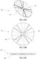
- FIG. 19A illustrates a perspective view of a spacer-locator that aligns 8 mating surfaces according to one embodiment of the present invention.
- FIG. 19B illustrates a side view of the embodiment illustrated in FIG. 19A .
- FIG. 19C illustrates a top view of the embodiment illustrated in FIGS. 19A and B.
- FIG. 20A illustrates a perspective view of a spacer-locator that aligns a concave and a convex surface according to one embodiment of the present invention.
- FIG. 20B illustrates a side view of the embodiment illustrated in FIG. 20A .
- FIG. 20C illustrates a top view of the embodiment illustrated in FIGS. 20A and B.
- FIG. 21A illustrates a transparent side view of two objects held in position by a spacer-locator with a cylinder locator and no spacer tabs according to the present invention.
- FIG. 21B illustrates a cross-sectional view of the embodiment illustrated in FIG. 21A .
- FIG. 22A illustrates a transparent perspective view of two objects held in position by a spacer-locator with a slot locator and no spacer tabs according to the present invention.
- FIG. 22B illustrates a transparent side view of the embodiment illustrated in FIG. 22A .
- FIG. 23A illustrates a perspective view of a spacer-locator that is integrated with one of the objects to be joined.
- FIG. 23B illustrates a side view of the embodiment illustrated in FIG. 23A .
- FIG. 23C illustrates a top view of the embodiment illustrated in FIGS. 23A and B.
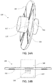
- FIG. 24A illustrates a cross-sectional, transparent, exploded perspective view of two objects held in position with a locator pin on one object and spacer tabs on the opposing object.
- FIG. 24B illustrates a cross-sectional side view of the embodiment illustrated in FIG. 24A .
- FIG. 24C illustrates a transparent perspective view of the embodiment illustrated in FIGS. 24A and B.
- FIG. 25A illustrates a side view of a cylindrical spacer-locator pin according to one embodiment of the present invention.
- FIG. 25B illustrates a side view of an ellipsoid spacer-locator pin according to one embodiment of the present invention.
- FIG. 26A illustrates a side view of a cylindrical spacer-locator pin integrally attached to a surface according to one embodiment of the present invention.
- FIG. 26B illustrates a side view of a semiellipsoid spacer-locator pin integrally attached to a surface according to one embodiment of the present invention.
- FIG. 27A illustrates a top perspective view of a door member with at least one side spacer without a locating pin according to one embodiment of the present invention.
- FIG. 27B illustrates a detail view of a side spacer without a locating pin according to one embodiment of the present invention.
- FIG. 27C illustrates a top view of a door member with at least one side spacer and at least one vertical spacer according to one embodiment of the present invention.
- FIG. 27D illustrates a side view of a vertical spacer according to one embodiment of the present invention.
- FIG. 27E illustrates a top perspective view of a door member with at least one side spacer and at least one vertical spacer, wherein the door member is inserted into a second door member according to one embodiment of the present invention.
- FIG. 27F illustrates a cross section view of a door member with a vertical spacer according to one embodiment of the present invention.
- the present invention is generally directed to a spacer-locator for use in spacing and locating two objects.
- the spacer-locator provides for spacing and locating two objects to be chemically or physically affixed to one another, such as with adhesive, by welding, by soldering, by vacuum, by mechanical fastening and the like.
- the present invention includes a spacer-locator that provides for a controlled thickness of an adhesive to be used in bonding and maintaining the bond between two bonded surfaces.
- the present invention includes a spacer-locator manufactured from the same material as the bonded surfaces.
- the present invention includes a spacer-locator including locating pins that provide additional shear strength.
- the present invention includes a spacer-locator that prevents rotation between two mating surfaces.
- Typical prior art spacers generally provide adhesive thickness tolerance or locational tolerance of adhered surfaces.
- the prior art does not disclose, teach, or suggest the use of a spacer-locator that provides for controlled spacing to be used in joining and maintaining the joint between two mating surfaces, enhanced positional tolerance for ease of assembly, and enhanced structural rigidity of joint by incorporating locator pins which provide a mechanical advantage against shear stress.
- the present invention is directed to a method of joining two or more surfaces and at least one spacer-locator with locator pins that provide location control and a mechanical advantage against shear stress.
- the method of the present invention includes locating holes in the two or more surfaces. The locating holes are created by drilling or, alternatively, the locating holes are created through a different process, by way of example and not limitation, incorporating the negative space into the design of the two or more surfaces.
- the method of the present invention further includes placing spacer-locators into the locating holes of one or more of the two or more surfaces.
- the method of the present invention further includes applying adhesive or other joining agent to one or more of the two or more surfaces.
- the present invention further includes the aligning of corresponding locating holes on each of the two or more surfaces that are being joined and pressing the surfaces together, thereby joining the surfaces and the at least one spacer's locator pins, aligning the surfaces in relation to one another.
- locator pins are placed in the corresponding locator holes, the two or more surfaces are aligned and pressed together, and the joining agent is subsequently injected into the gap between the two or more surfaces.
- the invention is a spacer-locator of a predetermined thickness that is capable of withstanding the pressure applied during a joining process, thereby maintaining the separation of the mating surfaces while ensuring controlled thickness of the joining agent between the mating surfaces.
- the spacer-locator preferably incorporates pins which serve as locators for aligning the mating surfaces and provide additional shear strength to the joint after the joining process has been completed.
- the spacer-locator includes a spacer body, to which the locator pins are reversibly or irreversibly attachable.
- the surfaces of the spacer-locator are created with different tolerances, depending on the use of the spacer. This reduces manufacturing costs associated with high-tolerance surfaces that are not critical to the bonding application.
- the locator pin sizing is manufactured to a tighter tolerance or looser tolerance depending on whether positioning jigs are used during the bonding process of the two surfaces.
- the spacer tab thickness is manufactured to a tighter tolerance or looser tolerance depending on the importance of the adhesive thickness or joint separation.
- the tolerance ranges from 1% to 15% of the specified spacer tab thickness.
- the locator pins act as a functional replacement to the positioning jigs currently needed to align components during the joining process.
- bonding a step to a platform requires numerous unique jigs to maintain the positional tolerance during the adhering process.
- An example of bonding a step to a platform includes, but is not limited to, the step attached to an elevated platform used with utility trucks.
- Implementing tight tolerance for a spacer-locator with locator pins provides the same benefits of the jig without the added expense of storage and maintenance of numerous jig assemblies. This provides for lower manufacturing costs and subsequently higher profits.
- the spacer tabs and locator pins are made of the same material as the mating surfaces. This maintains uniform material characteristics throughout the entire assembly, including by way of example and not limitation, conductivity, corrosion resistance, and aesthetic qualities. Suitable materials include, but are not limited to, fiberglass, plastics, metals, resins, epoxy, composite laminate, and/or ceramic.
- the spacer-locator is designed to prevent rotation of bonded surfaces.
- rotation is prevented between joined surfaces by incorporating two spacer-locators of the present invention on the same mating surfaces.
- rotation is prevented between mating surfaces by incorporating an anti-rotation feature into the spacer tab.
- the spacer-locator provides for controlling the degrees of freedom between two or more surfaces.
- degrees of freedom with respect to one another (six relative degrees of freedom): the x-, y- and z-axes and the theta, phi, and psi angles ( FIG. 1 ).
- the x-axis and y-axis are along the plane of the first mating surfaces and the z-axis traverses the interface of the first mating surfaces.
- the z-axis is perpendicular to the plane of the mating surfaces.
- the psi angle is in the plane of the first mating surfaces (around the z-axis); the phi angle is around the x-axis, and the theta angle is around y-axis.
- Adding a locator pin constrains two axes (x- and y-axes) and two rotational degrees of freedom (phi and theta) and therefore reduces the degrees of freedom to two.
- Adding an anti-rotation component constrains rotation around the z-axis (psi angle), removes another degree of freedom and reduces the degrees of freedom to one.
- Adding a spacer tab partially constrains a fifth degree of freedom (z-axis) and additionally constrains the phi and psi angles.
- a spacer-locator according to the present invention can constrain two objects to two or one degrees of freedom and can partially constrain the last degree of freedom.
- FIG. 2A is a side view that illustrates a preferred embodiment of the present invention.
- the spacer-locator 100 includes a spacer body 101 , spacer tabs 102 , and locator pins 103 .
- the spacer body 101 acts as the core of the spacer-locator 100 , and acts as a mounting surface for the spacer tabs 102 and the locator pins 103 .
- the spacer tabs 102 lay on a plane and extend outward perpendicularly from the direction of the locator pins 103 and outwardly from the spacer body 101 .
- the spacer body 101 , spacer tabs 102 , and locator pins 103 are formed from one piece of material.
- the locator pins 103 attach to the spacer body 101 through threaded members.
- the locator pins 103 attach to the spacer body 101 with adhesive.
- the spacer body is about 0.030′′ thick.
- the spacer body thickness is between 0.010′′ and 0.030′′.
- the spacer body thickness is between 0.030′′ and 0.1′′.
- the spacer includes a smooth surface where the locator pin is mounted with adhesive.
- the spacer body incorporates an internal threading for mechanical fastening of a locator pin.
- the spacer tabs have a thickness of about 0.030′′.
- the spacer tab thickness is between 0.010′′ and 0.030′′.
- the spacer tab thickness is between 0.030′′ and 0.1′′.
- the spacer tab thickness is determined by the final adhesive thickness requirements between the bonded surfaces.
- the spacer-locator including the spacer tabs and locator pins are created from a single piece of material.
- the spacer-locator is formed, milled, molded, stamped, and/or 3-D printed as one piece.
- the spacer tabs and locator pins are made of a different material than the mating material based on the joining application.
- the spacer tabs and locator pins are made of a material having a higher shear strength than the mating material and the mating agent.
- the shear strength of Methyl Methacrylate is approximately 3 ksi and the shear strength of carbon steel ranges from 36 to 120 ksi.
- the spacer-locator is formed from at least two pieces of material.
- the spacer body is formed, milled, molded, stamped, and/or 3-D printed separately from the locator pins. Locator pins are then selected and attached to the spacer body depending on the requirements of the bonded assembly. Attachment of the locator pins to the spacer body occurs through mechanical fastening, by way of example and not limitation, through the utilization of threaded members.
- the locator pins incorporate a threaded member with an external thread
- the spacer body incorporates a threaded member with internal threads.
- the spacer body incorporates external threads and the locator pins incorporates internal threads.
- the locator pins are attached with adhesive.
- Suitable adhesive includes, but is not limited to, laminates, hot adhesives, reactive adhesives, polyester-polyurethane resin, polyols-polyurethane resin, acrylic polymers-polyurethane resin, epoxy, methacrylate, and/or cyanoacrylate.
- the locator pins are attached through thermal bonding, including but not limited to, plastic welding, electric welding, tungsten arc welding and/or soldering.
- the locator pins are attached through the use of magnets within the locator pins and the spacer body. This modular design provides flexibility of the spacer-locator characteristics, thereby having the advantage of reduced costs as spacer-locators do not need to be custom-made for every bonding application.
- FIG. 2B is a perspective view of the spacer-locator embodiment illustrated in FIG. 2A .
- FIG. 2C is a top view of the spacer-locator illustrated in FIGS. 2A and B, further showing the centerline of the spacer tabs 104 .
- the spacer tabs 104 are offset randomly or non-randomly.
- the offset of the centerline of the spacer tabs 104 is governed by an equation, wherein the equation is, by way of example and not limitation, 360 degrees divided by the number of spacer tabs.
- An example is shown in FIG. 2C , where the centerlines of the three spacer tabs are offset non-randomly by 120 degrees around the vertical.
- the locator pins are sized and shaped according to the shear strength required of the assembly.
- Prior art spacers ultimately weaken the joint by displacing a portion of adhesive and providing no additional strength to the joint.
- the spacer-locator of the present invention addresses this weakness and improves upon the prior art by not only preventing the loss of strength at the joint by maintaining spacing, but by adding mechanical shear strength at the joint through the use of locator pins.
- the locator pins work in tandem with the shear strength associated with the joining agent.
- the locator pins are shaped to maximize the shear strength of the joint.
- FIG. 3A shows one embodiment of the present invention where the locator pins are shaped and sized for their ability to provide shear strength to the joint.
- FIG. 3A is a side view that illustrates an embodiment of the present invention.
- the spacer-locator 100 includes spacer tabs 102 , and locator pins 103 .
- the spacer tabs 102 act as the core of the spacer-locator 100 , and are a mounting surface for the locator pins 103 .
- the spacer tabs 102 lay on a plane and extend outward perpendicularly from the direction of the locator pins 103 .
- the spacer tabs 102 , and locator pins 103 are formed from one piece of material.
- the locator pins 103 attach to the spacer tabs 102 through threaded members.
- the locator pins 103 attach to the spacer tabs 102 with adhesive.
- FIG. 3B is a top view of the spacer-locator embodiment illustrated in FIG. 3A .
- FIG. 3C is a side view of the spacer-locator embodiment illustrated in FIGS. 3A and B, further showing an example of bonding surfaces 105 .
- FIG. 4A is a side view of the spacer-locator embodiment in FIG. 3A , wherein the locator pins 103 are hexagonal in shape.
- the hexagonal shape of the locator pins 103 advantageously prevents two substrates from rotating about the spacer-locator if only 1 spacer-locator is used in bonding the two substrates.
- FIG. 4B is a top view of the spacer-locator embodiment in FIG. 3B , wherein the locator pins 103 are hexagonal in shape.
- the spacer-locator contains two spacer tabs. In another alternative the spacer-locator contains more than two spacer tabs. In another embodiment the spacer-locator contains between three and eight spacer tabs. Alternatively, the spacer-locator contains one spacer tab.
- the spacer's locator pins incorporate anti-rotation features, thereby eliminating the need for the second spacer-locator in an assembly.
- the incorporated anti-rotation feature provides the benefit of reducing cost, weight, and assembly time.
- FIG. 5A is a perspective view of the spacer-locator embodiment in FIG. 3A , wherein the locator pins 103 are triangular in shape and the spacer-locator includes only one spacer tab 102 .
- the triangle shape of the locator pins 103 advantageously prevents two substrates from rotating about the spacer-locator even if only 1 spacer-locator is used in bonding the two substrates.
- the spacer-locator illustrated in FIG. 5A prevents rotation between bonded surfaces by incorporating an anti-rotation feature into the locator pin.
- FIG. 5B is a top view of the spacer-locator embodiment in FIG. 5A .
- FIG. 5C is a side view of the spacer-locator embodiment in FIG. 5A .
- FIG. 6A is a perspective view of the spacer-locator embodiment in FIG. 3A , wherein the locator pins 103 are slotted in shape.
- the slotted locator pins are advantageously the simplest method to machine.
- the shape of the slotted spacer-locator also advantageously provides for anti-rotation feature.
- FIG. 6B is a top view of the spacer-locator embodiment in FIG. 6A .
- FIG. 6C is a side view of the spacer-locator embodiment in FIG. 6A .
- FIG. 7A is a perspective view of the spacer-locator embodiment in FIG. 3A , wherein the locator pins 103 are double-square in shape.
- the double-square spacer-locator provides increased resistance to rotational motions of the two substrates to which the double-square spacer-locator is bonded.
- the double-square also provides greater contact area between the locator pin and the substrates than an equally sized slotted spacer-locator, thereby reducing the risk of deforming the substrates and/or spacer.
- FIG. 7B is a top view of the spacer-locator embodiment in FIG. 7A .
- FIG. 7C is a side view of the spacer-locator embodiment in FIG. 7A .
- the spacer tabs are any shape that is able to maintain a specified spacing between two substrates.
- the tabs can be planar or non-planar.
- Example profile shapes for spacer tabs are shown in FIG. 8 . This same figure also shows example cross-sectional shapes of the locator pins.
- FIG. 9A is a perspective view of a lattice structure spacer-locator according to one embodiment of the present invention.
- the spacer-locator 100 is shaped in a lattice structure.
- the spacer-locator 100 includes 12 locator pins 103 and 17 spacer tabs 102 .
- the spacer-locator 100 including the spacer tabs 102 , and locator pins 103 are formed from one piece of material.
- the locator pins 103 attach to the spacer tabs 102 through threaded members.
- the locator pins 103 attach to the spacer tabs 102 with adhesive.
- the locator pins 103 attach to the spacer tabs 102 with thermal bonding.
- the lattice design of the spacer-locator intentionally sacrifices adhesive contact area in order to maximize shear strength.
- the lattice structure spacer-locator is preferably made of a material with a higher shear strength than the joining agent utilized.
- the lattice structure spacer-locator is made out of a material with an approximately equivalent shear strength to the joining agent utilized.
- FIG. 9B is a side view of the spacer-locator embodiment illustrated in FIG. 9A .
- FIG. 9C is a top view of the spacer-locator embodiment illustrated in FIG. 9A .
- FIG. 10A is a perspective view of the spacer-locator embodiment illustrated in FIG. 9A , further illustrating the spacer-locator 100 in between bonded materials 105 .
- FIG. 10B is a side view of the spacer-locator embodiment illustrated in FIG. 10A , further identifying the individual locator pins 103 .
- FIG. 11A is a perspective view of a locator pin according to one embodiment of the present invention.
- the male locator pin 106 represents one half of the locator pin assembly, and includes threading 108 that mates with the female locator pin (illustrated as 107 in FIGS. 12A and B). Together, the male locator pin 106 and the female locator pin 107 attach to one or more spacer tabs, forming a spacer-locator.
- FIG. 11B is a perspective view of the locator pin embodiment illustrated in FIG. 11A .
- FIG. 12A is a perspective view of a locator pin according to one embodiment of the present invention.
- the female locator pin 107 represents one half of the locator pin assembly, and includes threading 108 that mates with the male locator pin (illustrated in FIG. 11A and FIG. 14A ).
- FIG. 12B is a perspective view of the locator pin embodiment illustrated in 10 A.
- FIG. 13A is a perspective view of a spacer tab according to one embodiment of the present invention.
- the spacer tab 102 incorporates fluid channels 109 and an opening 110 in the center of the spacer tab 102 for fitting locator pins.
- the spacer tab includes fluid channels in order to provide control over flow of fluids, such as adhesives, etching fluids, solvents, cleaners, primers, sealants, paints, gasses, dyes or other fluids used for the purpose of inspection, thermoset resins and/or thermoplastic resins.
- fluids such as adhesives, etching fluids, solvents, cleaners, primers, sealants, paints, gasses, dyes or other fluids used for the purpose of inspection, thermoset resins and/or thermoplastic resins.
- FIG. 13B is a top view of the spacer tab embodiment illustrated in FIG. 13A .
- FIG. 13C is a side view of the spacer tab embodiment illustrated in FIG. 13A .
- FIG. 14A is a perspective view of a spacer-locator embodiment utilizing the male locator pin illustrated in FIGS. 11A and B, the female locator pin illustrated in FIGS. 11A and B, and the spacer tab illustrated in FIGS. 13A-C , according to one embodiment of the present invention.
- the spacer-locator 100 includes a spacer tab 102 with fluid channels 109 , as well as a male locator pin 106 and a female locator pin 107 .
- the male locator pin 106 extends through an opening 110 in the center of the spacer tab 102 and mates with the female locator pin 107 .
- the male locator pin and female locator pin are operable to function with a variety of spacer tabs with different thicknesses.
- the fluid channels 109 of the spacer tab direct the flow of adhesive and other fluids outward from the center of the spacer tab.
- FIG. 14B is a side view of the spacer-locator embodiment illustrated in FIG. 14A , further illustrating the threading 108 that facilitates the mating of the male locator pin 106 and the female locator pin 107 .
- FIG. 15A is a perspective view of a spacer-locator according to one embodiment of the present invention.
- the spacer-locator 100 includes 2 locator pins 103 and a spacer tab 102 .
- the spacer tab 102 , and locator pins 103 are formed from one piece of material.
- the locator pins 103 attach to the spacer tab 102 through threaded members.
- the locator pins 103 attach to the spacer tab 102 with adhesive.
- FIG. 15B is a side view of the spacer-locator embodiment illustrated in FIG. 15A .
- FIG. 15C is a top view of the spacer-locator embodiment illustrated in FIG. 15A .
- the spacer-locator is shaped to allow the joining of more than two surfaces, wherein the multiple surfaces are not all on the same plane.
- FIG. 16A is a perspective view of another spacer-locator according to one embodiment of the present invention.
- the spacer-locator 100 includes spacer tabs 102 and locator pins 103 .
- the spacer-locator 100 including the spacer tabs 102 , and locator pins 103 are formed from one piece of material.
- the locator pins 103 attach to the spacer tabs 102 through threaded members.
- the locator pins 103 attach to the spacer tabs 102 with adhesive.
- the locator pins 103 attach to the spacer tabs 102 with thermal bonding.
- the spacer-locator illustrated in FIG. 16A is shaped to provide an additional spacer plane to allow the bonding of at least 3 surfaces.
- FIG. 16B is a side view of the spacer-locator embodiment illustrated in FIG. 16A .
- FIG. 16C is a top view of the spacer-locator embodiment illustrated in FIG. 16A .
- the spacer-locator allows the joining of at least 4 surfaces ( FIGS. 17A-C ).
- the locator pins are not perpendicular to the mating surface ( FIGS. 18A-B ). This allows for joining objects that cannot be inserted into the space orthogonally to the mating surfaces, or are angled with respect to the mating surfaces and not of sufficient size to accommodate a perpendicular locator pin.
- FIGS. 19A-C illustrates a spacer-locator for joining 8 surfaces wherein the anti-rotation feature is provided by the spacer tabs.
- the vertical tabs 111 in addition to maintaining the space between the surfaces, also prevent rotation of the surfaces because the orthogonal shape formed by two adjacent spacer-tabs prevents the rotation of the orthogonal objects being bonded.
- the present invention also provides for spacer-locators designed and configured to join non-planar surfaces together.
- An example spacer-locator with non-planar spacer tab 112 is shown in FIGS. 20A-C .
- a partial-sphere surface spacer-locator is illustrated which is used to join together a concave and a convex surface.
- Another example includes a partial-cylinder surface spacer-locator (not shown).
- the spacer-locator contains no spacer tabs.
- the desired separation is maintained by using at least one spacer locator pin with a length that is greater than the combined depth of the positioning holes.
- the spacer locator pin is thus sized to provide the desired separation between the mating surfaces and the desired mechanical strength against shear stress.
- the spacer locator pin is shaped as a prolate spheroid, cylinder ( FIGS. 21A &B) or slot ( FIGS. 22A &B)
- the slot shape has a cross-section that is an elongated rectangular with rounded corners; this cross-section shape is also called stadium, discorectangle, or obround.
- FIGS. 23A-C Another embodiment provides for a spacer-locator integrated into one of the objects to be joined ( FIGS. 23A-C ).
- FIG. 23A illustrates a perspective view of two spacer-locators integrated into an object.
- FIGS. 23B and C are a side view and a top view of the embodiment, respectively.
- the mating object contains the corresponding locator hole(s).
- the present invention provides a system for joining two objects together, wherein the spacer-locator is integral with one of the objects and the other object contains a corresponding locator hole.
- the spacer tab and the locator pin are located on the same object. Alternatively, they are located on opposing objects, as shown in FIGS. 24A-C .
- the spacer-locator and/or locator pin are preferably manufactured with a material that has the same or similar intrinsic material properties as the mating surfaces.
- the spacer-locator material has the same or similar electrical conductivity, thermal expansion, corrosion resistance, and/or aesthetic qualities as the mating surfaces.
- the various components of the spacer-locator are attached to one another using any acceptable means or combinations of means.
- the components are attached to one another by mechanical fastening, by way of example and not limitation, through the utilization of threaded members.
- the components are attached using adhesives, that include, but are not limited to, laminates, hot adhesives, reactive adhesives, polyester-polyurethane resin, polyols-polyurethane resin, acrylic polymers-polyurethane resin, epoxy, methacrylate, and/or cyanoacrylate.
- the components are attached by thermal bonding, including but not limited to, plastic welding, electric welding, tungsten arc welding and/or soldering.
- the components are attached through the use of magnets within the locator pins and the spacer body.
- FIGS. 25A and 25B illustrate one embodiment of the present invention, wherein the spacer-locator includes only a spacer-locator pin, wherein the spacer-locator pin is constructed without a separate spacer.
- a spacer-locator pin 2401 both separates two surfaces and positions the surfaces without the need for separate spacer elements.
- the spacer-locator pin 2401 sits within spacer-locator slots 2403 , wherein a depth of the spacer locator slot 2403 A is less than half of the length of the spacer-locator pin 2401 A when the spacer-locator slots are of equal depth.
- the spacer-locator slots have differing depths, wherein a depth of the first spacer-locator slot 2403 A is different than a depth of the second spacer-locator slot 2403 B, and wherein a sum of the first depth 2403 A and the second depth 2403 B is less than the length of the spacer-locator pin 2401 A in order to provide space between the surfaces.
- These constructions each provide space between the two surfaces while simultaneously providing positioning.
- the spacer-locator pin 2401 and the spacer-locator slots 2403 restricts movement in at least two dimensions (e.g., x-axis and y-axis) and restricts rotation in at least one or two dimensions (e.g., ⁇ and ⁇ ).
- the spacer-locator pin 2401 is operable to be constructed with any shape, size, or dimensions as disclosed in reference to previous spacers and locator pins, including polygonal constructions and shapes that prevent rotation in a third dimension (e.g., ⁇ ).
- the spacer-locator pin 2401 is combined with at least one additional spacer locator pin, wherein the at least one additional spacer-locator pin is either connected to the spacer-locator pin 2401 or operates separately, and wherein the combination prevents rotation in at least one additional dimension (e.g., ⁇ ).
- the spacer-locator pin is operable to be constructed from any shape, size, or dimension that both restricts movement and rotation and provides space between the surfaces.
- FIG. 25B illustrates one alternative embodiment, wherein an ellipsoid spacer locator-pin 4205 prevents movement in two directions (i.e., x-axis and y-axis).
- a corresponding dome-shaped spacer-locator slot 2407 has a depth 2407 A equal to less than half of the height of the spacer-locator pin 2405 A when slots on both surfaces have an equal depth ( 2407 A, 2407 B).
- the depth of the first spacer-locator slot 2407 A and the depth of the second spacer-locator slot 2407 B are different, and a sum of the depth of the first spacer locator depth 2407 A and the second spacer locator depth 2407 B is less than a height of the spacer 2405 A.
- the ellipsoid spacer-locator pin is combined with at least one additional ellipsoid spacer-locator pin (and/or any other shaped spacer-locator pin) to prevent rotation in at least one direction (e.g., ⁇ or ⁇ ).
- spacer-locator pins and spacer-locator slots are exaggerated for clarity, lower tolerances are preferably constructed for a tighter fit (e.g., a close running fit or a sliding fit) for attachment of the spacer-locator pin to the spacer-locator slot.
- the spacer-locator pin is adhered, attached, or secured in place via physical, mechanical, or chemical means, including by adhesive, welding, magnetism, pins, screws, bolts, nuts, or any other method known in the art of mechanical design or disclosed herein.
- FIGS. 26A and 26B illustrate another embodiment of the spacer-locator pin, wherein the spacer-locator pin is integrally constructed from, attached to, or secured to one surface.
- the cylindrical spacer locator pin 2501 is integral with a first surface 2509 and sits within the spacer-locator slot 2503 of a second surface.
- the extruded portion of the second surface that makes up the spacer-locator pin 2501 has a height 2501 A that is greater than the height of the spacer-locator slot 2503 A.
- FIG. 25A illustrates another embodiment of the spacer-locator pin, wherein the spacer-locator pin is integrally constructed from, attached to, or secured to one surface.
- the cylindrical spacer locator pin 2501 is integral with a first surface 2509 and sits within the spacer-locator slot 2503 of a second surface.
- the extruded portion of the second surface that makes up the spacer-locator pin 2501 has a height 2501 A that is greater than the height of the space
- a semiellipsoid spacer-locator pin 2505 is integral with a first surface 2511 and sits within the spacer-locator slot 2507 of a second surface.
- the extruded portion of the second surface that makes up the spacer-locator pin 2505 has a height 2505 A that is greater than the height of the spacer-locator slot 2507 A.
- spacer-locator slots of FIG. 25A, 25B, 26A , or 26 B either match or do not match a profile of the spacer-locator pin and/or include pins, locks, sliders, snaps, or other retaining mechanisms to improve retention of the spacer-locators.
- the spacer-locator includes any of the elements disclosed in prior spacer or locator pin embodiments, such as shapes, cross sections, sizes, threading, holes, or other constructions.
- FIG. 27A illustrates one embodiment of a spacer-locator with only spacer tabs and no locator pins.
- at least one spacer 2601 is arranged along a surface 2603 of a door member 2605 , wherein the spacers control a space between the surface 2603 and a second surface (see FIG. 27E ).
- a thickness of the spacer 2601 determines a distance between the surface 2603 and a second surface, and two or more spacers on two or more surfaces restrict rotation along one or more axes (e.g., ⁇ ).
- each of the spacers are each equal in thickness.
- the spacers are different thicknesses.
- spacers along a first surface are 0.5 inches (12.7 millimeters) thick, and spacers along a second surface are 0.25 inches (6.35 millimeters) thick.
- spacers of the illustrated embodiment are matched with retaining elements such as embossed slots, sleeves, holes, or other similar constructions on a second surface, wherein the retaining elements provide positioning, locating, and support to the spacers.
- the spacers in this embodiment are thicker, wider, or otherwise larger than the retaining elements in order to maintain spacing between a surface on which spacer is constructed and a surface on which the retaining element is constructed.
- the retaining element is an embossed slot with a depth of 0.5 inches (12.7 millimeters), and the spacer has a depth of greater than 0.5 inches (12.7 millimeters).
- the retaining element is cone shaped sleeve with a base diameter of 1 inch (25.4 millimeters), and the spacer is cone shaped with a base diameter greater than 1 inch (25.4 millimeters), which ensures that the conic retaining element cannot engage past the 1 inch (25.4 millimeter) diameter of the spacer and maintains space between the two surfaces.
- FIG. 27B illustrates a detail view of a spacer 2601 , wherein the spacer 2601 is tapered such that a slope of at least part of the spacer 2601 is steeper than that of the surface 2603 to provide thickness and separate the surface 2603 from a second surface.
- FIG. 27C illustrates a top view of a door member 2605 including spacers according to one embodiment of the present invention.
- Side spacers 2601 without locator pins, as illustrated in FIGS. 27A and 27B are included as well as vertical spacer pins 2607 .
- Vertical spacer pins 2607 are spacers that provide separation between the door member 2605 and a second surface in a similar manner to the spacer-locator pins illustrated in FIGS. 26A-26B .
- the vertical spacers 2607 in the illustrated embodiment extend from a bottom surface of the door member 2605 .
- the vertical spacer pins 2607 are operable to have any shape disclosed herein for spacers and pins, including cylindrical, hemispherical, wedge shaped, or any other suitable constructions, including those with cross sections that are triangular, star, rectangle and/or any other suitable shape.
- FIG. 27D illustrates a side view of a spacer pin 2607 according to one embodiment of the present invention.
- FIG. 27E illustrates one embodiment of the door member 2605 inserted into a second door member 2609 , wherein at least one side spacer 2601 and at least one vertical spacer pin both provide separation of surfaces on the door member 2605 from surfaces of the second door member 2609 .
- the second door member 2609 is only in contact with spacers and spacer pins of the door member 2601 .
- FIG. 27F illustrates a cross section of the door member 2605 with one embodiment of a vertical spacer 2607 , wherein the vertical spacer has a rounded shape and is extends from a bottom of the door member 2605 .
- Each of the above disclosed spacers and pins are preferably removably or irremovably joined together or joined to a surface, a sleeve, a hole, and/or any other spacing and positioning element via physical bonding, chemical bonding, mechanical attachment, mechanical interlocking, magnetism, reversible adhesive, irreversible adhesive, welding including plastic welding, infusion, lamination, and/or vacuum attachment.
- horizontal spacers, vertical spacers, or any other spacers or pins are all attached or integrated with a first surface or a second surface, or not all of a plurality of spacers and pins are attached or integrated with the same surface.
- one or more spacers are integral with a first surface, and one or more additional spacers are integral with a second surface.
- at least one first spacer tab is integral with a first mating surface of a first object or a first mating surface of a second object, wherein the at least one first spacer tab is in contact with an opposite surface of the first mating surface of the first object or an opposite surface of the first mating surface of the second object, and at least one second spacer tab is integral with a second mating surface of the first object or a second mating surface of the second object, wherein the at least one second spacer tab is in contact with an opposite surface of the second mating surface of the first object or an opposite surface of the second mating surface of the second object;
- the spacer-locator may be different shapes.
- the locator pins may be different shapes and sizes to provide required strength characteristics or accommodate manufacturing processes.
- this invention is highly adjustable, customizable and adaptable.
- the above-mention examples are just some of the many configurations that the mentioned components can take on. All modifications and improvements have been deleted herein for the sake of conciseness and readability but are properly within the scope of the present invention.
Abstract
Description
Claims (21)
Priority Applications (3)
| Application Number | Priority Date | Filing Date | Title |
|---|---|---|---|
| US16/663,034 US11220066B2 (en) | 2016-10-03 | 2019-10-24 | Spacer for use in precision bonding applications that provides enhanced shear strength |
| US17/571,027 US11639035B2 (en) | 2016-10-03 | 2022-01-07 | Spacer for use in precision bonding applications that provides enhanced shear strength |
| US18/139,704 US20230256686A1 (en) | 2016-10-03 | 2023-04-26 | Spacer for use in precision bonding applications that provides enhanced shear strength |
Applications Claiming Priority (3)
| Application Number | Priority Date | Filing Date | Title |
|---|---|---|---|
| US201662403418P | 2016-10-03 | 2016-10-03 | |
| US15/722,718 US10456991B2 (en) | 2016-10-03 | 2017-10-02 | Spacer for use in precision bonding applications that provides enhanced shear strength |
| US16/663,034 US11220066B2 (en) | 2016-10-03 | 2019-10-24 | Spacer for use in precision bonding applications that provides enhanced shear strength |
Related Parent Applications (1)
| Application Number | Title | Priority Date | Filing Date |
|---|---|---|---|
| US15/722,718 Continuation-In-Part US10456991B2 (en) | 2016-10-03 | 2017-10-02 | Spacer for use in precision bonding applications that provides enhanced shear strength |
Related Child Applications (1)
| Application Number | Title | Priority Date | Filing Date |
|---|---|---|---|
| US17/571,027 Continuation US11639035B2 (en) | 2016-10-03 | 2022-01-07 | Spacer for use in precision bonding applications that provides enhanced shear strength |
Publications (2)
| Publication Number | Publication Date |
|---|---|
| US20200055262A1 US20200055262A1 (en) | 2020-02-20 |
| US11220066B2 true US11220066B2 (en) | 2022-01-11 |
Family
ID=69524422
Family Applications (3)
| Application Number | Title | Priority Date | Filing Date |
|---|---|---|---|
| US16/663,034 Active 2037-11-21 US11220066B2 (en) | 2016-10-03 | 2019-10-24 | Spacer for use in precision bonding applications that provides enhanced shear strength |
| US17/571,027 Active US11639035B2 (en) | 2016-10-03 | 2022-01-07 | Spacer for use in precision bonding applications that provides enhanced shear strength |
| US18/139,704 Pending US20230256686A1 (en) | 2016-10-03 | 2023-04-26 | Spacer for use in precision bonding applications that provides enhanced shear strength |
Family Applications After (2)
| Application Number | Title | Priority Date | Filing Date |
|---|---|---|---|
| US17/571,027 Active US11639035B2 (en) | 2016-10-03 | 2022-01-07 | Spacer for use in precision bonding applications that provides enhanced shear strength |
| US18/139,704 Pending US20230256686A1 (en) | 2016-10-03 | 2023-04-26 | Spacer for use in precision bonding applications that provides enhanced shear strength |
Country Status (1)
| Country | Link |
|---|---|
| US (3) | US11220066B2 (en) |
Families Citing this family (2)
| Publication number | Priority date | Publication date | Assignee | Title |
|---|---|---|---|---|
| US11220066B2 (en) | 2016-10-03 | 2022-01-11 | Altec Industries, Inc. | Spacer for use in precision bonding applications that provides enhanced shear strength |
| TWI828005B (en) * | 2021-11-18 | 2024-01-01 | 達霆精密工業有限公司 | Fastener structure, usage and assembly methods |
Citations (19)
| Publication number | Priority date | Publication date | Assignee | Title |
|---|---|---|---|---|
| US3919452A (en) | 1973-10-23 | 1975-11-11 | Vitta Corp | Precision bonding system |
| US3947311A (en) | 1972-11-23 | 1976-03-30 | Friedrich G. K. Jarchow | Method and apparatus for cementing in the manufacture of double-pane insulating glass units |
| US4346918A (en) | 1979-05-07 | 1982-08-31 | Lycan Goodwin A | Pipe spacer used in welding |
| US4512436A (en) * | 1983-07-01 | 1985-04-23 | Altec Industries, Inc. | Platform rotating mechanism for aerial devices |
| US4786094A (en) | 1987-10-06 | 1988-11-22 | Chrysler Motors Corporation | Mounting clip including break-away spacer element |
| US4825342A (en) * | 1988-05-27 | 1989-04-25 | Chrysler Motors Corporation | Vehicle headlamp assembly locator |
| US5037334A (en) | 1990-11-30 | 1991-08-06 | Amp Corporated | Connector with equal lateral force contact spacer plate |
| US5328087A (en) | 1993-03-29 | 1994-07-12 | Microelectronics And Computer Technology Corporation | Thermally and electrically conductive adhesive material and method of bonding with same |
| US5848152A (en) * | 1995-09-26 | 1998-12-08 | Motorola, Inc. | Communication device having interchangeable faceplates and active keypad cover |
| US6383843B1 (en) | 2000-04-17 | 2002-05-07 | Advanced Micro Devices, Inc. | Using removable spacers to ensure adequate bondline thickness |
| US20040016790A1 (en) * | 2002-07-23 | 2004-01-29 | Bahry Joseph M. | Method and tool for aligning piping components |
| US6826928B2 (en) | 1998-12-04 | 2004-12-07 | Terastor Corporation | Methods for positioning and bonding elements in substrates |
| US20060049669A1 (en) | 2004-09-03 | 2006-03-09 | Nissan Technical Center North America, Inc. | Windshield spacer |
| US20080024926A1 (en) | 2006-07-27 | 2008-01-31 | Esgw Holdings Limited | Self-fixturing pivoting actuator |
| US20090103164A1 (en) * | 2007-10-19 | 2009-04-23 | Pixtronix, Inc. | Spacers for maintaining display apparatus alignment |
| US20100136396A1 (en) | 2009-08-21 | 2010-06-03 | Tesla Motors, Inc. | Cell Separator for Minimizing Thermal Runaway Propagation within a Battery Pack |
| US20160037921A1 (en) * | 2014-08-06 | 2016-02-11 | Airbus Operations Gmbh | Adhesive retainer for fixing to a structure |
| US9550475B1 (en) * | 2015-09-09 | 2017-01-24 | Altec Industries, Inc. | Securely deploying outrigger foot |
| US20180093425A1 (en) * | 2016-10-03 | 2018-04-05 | Altec Industries, Inc. | Spacer for use in precision bonding applications that provides enhanced shear strength |
Family Cites Families (11)
| Publication number | Priority date | Publication date | Assignee | Title |
|---|---|---|---|---|
| US3042572A (en) * | 1958-05-28 | 1962-07-03 | G J Verhulst Reneedling Co Inc | Method of assembling and cementing pins in the groove of a faller bar |
| US7521292B2 (en) * | 2004-06-04 | 2009-04-21 | The Board Of Trustees Of The University Of Illinois | Stretchable form of single crystal silicon for high performance electronics on rubber substrates |
| US9161448B2 (en) * | 2010-03-29 | 2015-10-13 | Semprius, Inc. | Laser assisted transfer welding process |
| DE112011101135B4 (en) * | 2010-03-29 | 2021-02-11 | X-Celeprint Limited | Electrically connected fields of active components in transfer printing technology |
| US8555583B2 (en) * | 2010-04-02 | 2013-10-15 | Romeo Ilarian Ciuperca | Reinforced insulated concrete form |
| US9899329B2 (en) * | 2010-11-23 | 2018-02-20 | X-Celeprint Limited | Interconnection structures and methods for transfer-printed integrated circuit elements with improved interconnection alignment tolerance |
| US8889485B2 (en) * | 2011-06-08 | 2014-11-18 | Semprius, Inc. | Methods for surface attachment of flipped active componenets |
| TWI651784B (en) * | 2014-06-18 | 2019-02-21 | 愛爾蘭商艾克斯瑟樂普林特有限公司 | System and method for controlling release of a transferable semiconductor structure |
| WO2016183845A1 (en) * | 2015-05-21 | 2016-11-24 | Goertek.Inc | Transferring method, manufacturing method, device and electronic apparatus of micro-led |
| US10468363B2 (en) * | 2015-08-10 | 2019-11-05 | X-Celeprint Limited | Chiplets with connection posts |
| US11220066B2 (en) | 2016-10-03 | 2022-01-11 | Altec Industries, Inc. | Spacer for use in precision bonding applications that provides enhanced shear strength |
-
2019
- 2019-10-24 US US16/663,034 patent/US11220066B2/en active Active
-
2022
- 2022-01-07 US US17/571,027 patent/US11639035B2/en active Active
-
2023
- 2023-04-26 US US18/139,704 patent/US20230256686A1/en active Pending
Patent Citations (24)
| Publication number | Priority date | Publication date | Assignee | Title |
|---|---|---|---|---|
| US3947311A (en) | 1972-11-23 | 1976-03-30 | Friedrich G. K. Jarchow | Method and apparatus for cementing in the manufacture of double-pane insulating glass units |
| US3919452A (en) | 1973-10-23 | 1975-11-11 | Vitta Corp | Precision bonding system |
| US4346918A (en) | 1979-05-07 | 1982-08-31 | Lycan Goodwin A | Pipe spacer used in welding |
| US4512436A (en) * | 1983-07-01 | 1985-04-23 | Altec Industries, Inc. | Platform rotating mechanism for aerial devices |
| US4786094A (en) | 1987-10-06 | 1988-11-22 | Chrysler Motors Corporation | Mounting clip including break-away spacer element |
| US4825342A (en) * | 1988-05-27 | 1989-04-25 | Chrysler Motors Corporation | Vehicle headlamp assembly locator |
| US5037334A (en) | 1990-11-30 | 1991-08-06 | Amp Corporated | Connector with equal lateral force contact spacer plate |
| US5328087A (en) | 1993-03-29 | 1994-07-12 | Microelectronics And Computer Technology Corporation | Thermally and electrically conductive adhesive material and method of bonding with same |
| US5848152A (en) * | 1995-09-26 | 1998-12-08 | Motorola, Inc. | Communication device having interchangeable faceplates and active keypad cover |
| US6826928B2 (en) | 1998-12-04 | 2004-12-07 | Terastor Corporation | Methods for positioning and bonding elements in substrates |
| US6383843B1 (en) | 2000-04-17 | 2002-05-07 | Advanced Micro Devices, Inc. | Using removable spacers to ensure adequate bondline thickness |
| US6824038B2 (en) | 2002-07-23 | 2004-11-30 | Joseph M. Bahry | Method and tool for aligning piping components |
| US20040016790A1 (en) * | 2002-07-23 | 2004-01-29 | Bahry Joseph M. | Method and tool for aligning piping components |
| US20060049669A1 (en) | 2004-09-03 | 2006-03-09 | Nissan Technical Center North America, Inc. | Windshield spacer |
| US8040638B2 (en) | 2006-07-27 | 2011-10-18 | Esgw Holdings Limited | Self-fixturing pivoting actuator |
| US20080024926A1 (en) | 2006-07-27 | 2008-01-31 | Esgw Holdings Limited | Self-fixturing pivoting actuator |
| US20090103164A1 (en) * | 2007-10-19 | 2009-04-23 | Pixtronix, Inc. | Spacers for maintaining display apparatus alignment |
| US20100136396A1 (en) | 2009-08-21 | 2010-06-03 | Tesla Motors, Inc. | Cell Separator for Minimizing Thermal Runaway Propagation within a Battery Pack |
| US8367239B2 (en) | 2009-08-21 | 2013-02-05 | Tesla Motors, Inc. | Cell separator for minimizing thermal runaway propagation within a battery pack |
| US20130078494A1 (en) | 2009-08-21 | 2013-03-28 | Tesla Motors, Inc. | Rigid Cell Separator for Minimizing Thermal Runaway Propagation within a Battery Pack |
| US8481191B2 (en) | 2009-08-21 | 2013-07-09 | Tesla Motors, Inc. | Rigid cell separator for minimizing thermal runaway propagation within a battery pack |
| US20160037921A1 (en) * | 2014-08-06 | 2016-02-11 | Airbus Operations Gmbh | Adhesive retainer for fixing to a structure |
| US9550475B1 (en) * | 2015-09-09 | 2017-01-24 | Altec Industries, Inc. | Securely deploying outrigger foot |
| US20180093425A1 (en) * | 2016-10-03 | 2018-04-05 | Altec Industries, Inc. | Spacer for use in precision bonding applications that provides enhanced shear strength |
Also Published As
| Publication number | Publication date |
|---|---|
| US20200055262A1 (en) | 2020-02-20 |
| US20220126526A1 (en) | 2022-04-28 |
| US20230256686A1 (en) | 2023-08-17 |
| US11639035B2 (en) | 2023-05-02 |
Similar Documents
| Publication | Publication Date | Title |
|---|---|---|
| US20230256686A1 (en) | Spacer for use in precision bonding applications that provides enhanced shear strength | |
| KR200468005Y1 (en) | lead frame structure, packing structure and lighting unit thereof | |
| KR101800427B1 (en) | Work pallet positioning and affixing device | |
| US10456991B2 (en) | Spacer for use in precision bonding applications that provides enhanced shear strength | |
| CN104093999B (en) | For connecting method and the component connection system of two components | |
| TW201700208A (en) | Welding fastener and structure of welding on circuit board thereof | |
| US10307652B2 (en) | Climbing hold assembly having load dissipative effect | |
| US20170289420A1 (en) | Imager module for a vehicle camera and method for the manufacture thereof | |
| US20150023757A1 (en) | Housing with nut and method for fixing the nut in the housing | |
| TWM470294U (en) | Placing tool | |
| JP2007180281A (en) | Heat conductive sheet and electronic component assembly | |
| US7816627B2 (en) | Attachment system for attaching an electric cable to a glass pane to provide electricity thereto | |
| JP5153316B2 (en) | Semiconductor package heat sink and plating method thereof | |
| CN104203495A (en) | Magnetic chuck | |
| CN106767589B (en) | Three-coordinate measuring method and device for clamp block type parts | |
| US10658262B2 (en) | Pin flexure array | |
| JP4881798B2 (en) | Member joining method and panel structure | |
| TW202016611A (en) | Display device | |
| CN104124561A (en) | Electrical connector assembly and mounting structure thereof | |
| US20130032313A1 (en) | Heat-dissipation unit and method of manufacturing same | |
| TWM543742U (en) | Welding fastener and structure of its welding on circuit board | |
| TWI620486B (en) | Package for active electronics | |
| KR101634657B1 (en) | Fastening system for add-on parts on a vehicle having a profile-like connection part vehicle having such a fastening system | |
| JP2016205552A (en) | Seal sticking jig and seal sticking method | |
| CN210715399U (en) | Connecting assembly for connecting hard material |
Legal Events
| Date | Code | Title | Description |
|---|---|---|---|
| FEPP | Fee payment procedure |
Free format text: ENTITY STATUS SET TO UNDISCOUNTED (ORIGINAL EVENT CODE: BIG.); ENTITY STATUS OF PATENT OWNER: LARGE ENTITY |
|
| STPP | Information on status: patent application and granting procedure in general |
Free format text: APPLICATION DISPATCHED FROM PREEXAM, NOT YET DOCKETED |
|
| STPP | Information on status: patent application and granting procedure in general |
Free format text: DOCKETED NEW CASE - READY FOR EXAMINATION |
|
| AS | Assignment |
Owner name: ALTEC INDUSTRIES, INC., MISSOURI Free format text: ASSIGNMENT OF ASSIGNORS INTEREST;ASSIGNOR:HEGG, JACE;REEL/FRAME:055016/0907 Effective date: 20200715 |
|
| AS | Assignment |
Owner name: ALTEC INDUSTRIES, INC., MISSOURI Free format text: ASSIGNMENT OF ASSIGNORS INTEREST;ASSIGNORS:MCKINNEY, RYAN J.;HOFFMANN, KYLE E.;SIGNING DATES FROM 20170727 TO 20170731;REEL/FRAME:055030/0858 |
|
| STPP | Information on status: patent application and granting procedure in general |
Free format text: NON FINAL ACTION MAILED |
|
| STPP | Information on status: patent application and granting procedure in general |
Free format text: RESPONSE TO NON-FINAL OFFICE ACTION ENTERED AND FORWARDED TO EXAMINER |
|
| STPP | Information on status: patent application and granting procedure in general |
Free format text: FINAL REJECTION MAILED |
|
| STPP | Information on status: patent application and granting procedure in general |
Free format text: RESPONSE AFTER FINAL ACTION FORWARDED TO EXAMINER |
|
| STPP | Information on status: patent application and granting procedure in general |
Free format text: NOTICE OF ALLOWANCE MAILED -- APPLICATION RECEIVED IN OFFICE OF PUBLICATIONS |
|
| STPP | Information on status: patent application and granting procedure in general |
Free format text: PUBLICATIONS -- ISSUE FEE PAYMENT RECEIVED |
|
| STPP | Information on status: patent application and granting procedure in general |
Free format text: PUBLICATIONS -- ISSUE FEE PAYMENT VERIFIED |
|
| STCF | Information on status: patent grant |
Free format text: PATENTED CASE |