US11219985B2 - Wrench for maximizing torque - Google Patents
Wrench for maximizing torque Download PDFInfo
- Publication number
- US11219985B2 US11219985B2 US16/180,249 US201816180249A US11219985B2 US 11219985 B2 US11219985 B2 US 11219985B2 US 201816180249 A US201816180249 A US 201816180249A US 11219985 B2 US11219985 B2 US 11219985B2
- Authority
- US
- United States
- Prior art keywords
- fastener
- protrusions
- wrench
- open end
- protrusion
- Prior art date
- Legal status (The legal status is an assumption and is not a legal conclusion. Google has not performed a legal analysis and makes no representation as to the accuracy of the status listed.)
- Active, expires
Links
Images


Classifications
-
- B—PERFORMING OPERATIONS; TRANSPORTING
- B25—HAND TOOLS; PORTABLE POWER-DRIVEN TOOLS; MANIPULATORS
- B25B—TOOLS OR BENCH DEVICES NOT OTHERWISE PROVIDED FOR, FOR FASTENING, CONNECTING, DISENGAGING, OR HOLDING
- B25B13/00—Spanners; Wrenches
- B25B13/02—Spanners; Wrenches with rigid jaws
- B25B13/08—Spanners; Wrenches with rigid jaws of open jaw type
Definitions
- This invention relates to an improved tool for turning polygonal fasteners, and in particular to improved open-end wrenches for applying maximum torque to hexagonal fasteners, even in the event that such fasteners have rounded corners.
- open-end wrench A major improvement in open-end wrenches is disclosed in commonly assigned U.S. Pat. No. 6,907,805 (Wright et al. 2005), which open-end wrench is known as the WRIGHT GRIP® wrench.
- the latter wrench has opposing jaws leading to a throat from its open ends.
- the forward facing ends of the jaws are planar and parallel, and they diverge in serrated sections as they lead to the throat to reduce contact with the rear corners of the fastener.
- There are arcuate rear corners which avoid contact with the rear side corners of the fastener and which eliminate stress concentration points.
- the throat is in part defined by gentle curves or flat surfaces leading to a central arc for providing more metal to the throat to stiffen the jaws.
- U.S. Pat. No. 6,443,038 (Hsieh) describes an open-end wrench having a pair of jaws with a nest connecting the two jaws to form a mouth.
- a first convex surface portion on the first jaw driving surface and a first transverse tooth, a second transverse tooth a second convex surface portion on the second jaw surface is provided.
- the two convex surface portions of the second jaw are arranged in a predetermined distance from the first convex surface portion of the first jaw driving surface.
- the distance between the first transverse tooth and the second transverse tooth is a fraction of the distance between the first convex surface portion of the first jaw driving surface and the first transverse tooth.
- an open end wrench has a jaw for screwing or unscrewing a nut.
- the fork or jaw has two jaws or branches for screwing in or unscrewing.
- the groove of the fork provides supporting zones for the proper positioning of the nut.
- an open-end wrench is provided.
- a first convex surface portion is provided on the first jaw driving surface, and a first transverse tooth, a second transverse tooth and a second convex surface is provided on the second jaw driving surface.
- U.S. Pat. No. 3,868,873 discloses an open-end wrench having opposed, spaced-apart jaws, one of the jaws a torqueing jaw and the other being a backup jaw having a planar working surface.
- the torqueing jaw has a braking surface and parallel to the backup jaw, the torqueing jaw having an arcuate surface adjacent the braking surface and the torqueing jaw having a ratcheting surface adjacent the arcuate surface.
- a ratcheting wrench for a hexagonal fastener has a body portion and opposing jaws.
- the first jaw has an inner peripheral surface facing the member receiving area having four contiguous torqueing surfaces configured to receive a hexagonal member.
- the torqueing surfaces are at an angle of 120°
- the second jaw has an inner peripheral surface facing the member receiving area having four contiguous torqueing surfaces configured to receive a hexagonal member, each of which being at an angle of 120° relative to any torqueing surface.
- an open end wrench has a number of 90 or 120 notches for square or hexagonal nuts to give them a series of small turns when in a confined place.
- an open end wrench with two heads can accept fasteners of different nominal sizes.
- Each head has a first jaw bearing, a convex interior surface facing the interior surface of a second jaw.
- the second jaw has plural pair of intersecting facets.
- the included angle formed between the intersecting facets is greater than 90° and less than 120°, and in another embodiment, the included angle is greater than 70° and less than 90°.
- Another object of the present invention is to provide an improved open-end wrench for applying the maximum torque to a fastener, where the latter can be a nut, to facilitate the turning of the nut for either installing the nut on a bolt or removing the nut from the bolt, for removing a bolt having a polygonal head, such as a hexagonal head, from a threaded hole, or the like.
- a yet further object of the invention is the provision of an open-end wrench for applying maximum torque to a hexagonal or other polygonal fastener, even when such fastener has one or more rounded corners.
- Another object of the invention is the provision of a corresponding set of open-end wrenches which is most effective in turning particular sizes of fasteners, and wherein at least one open-end wrench of the set is for applying maximum torque to a hexagonal or other polygonal fastener even when such fastener has one or more rounded corners.
- a further object of the present invention is the provision of a set of open-end wrenches of specified sizes for turning a set of fasteners of corresponding sizes for imparting a respective maximum torque to the respective sizes of fasteners, and wherein at least one open-end wrench of the set is for applying maximum torque to a hexagonal or other polygonal fastener even when such fastener has one or more rounded corners.
- An additional object of the present invention is to provide a set of open-end wrenches of varying sizes for turning hexagonal fasteners of like corresponding sizes while applying maximum torque to the respective sizes of hexagonal fasteners, and wherein at least one open-end wrench of the set is for applying maximum torque to a hexagonal or other polygonal fastener even when such fastener has one or more rounded corners.
- Another object of the present invention is to provide a set of open-end wrenches of various sizes for turning polygonal fasteners of the corresponding sizes for imparting maximum torque on the respective fasteners to affect the turning of the respective fasteners, even if the respective fasteners have rounded corners.
- Open-end wrenches having serrations or protrusions on the opposing working surfaces of the jaws which face each other are known by those skilled in the art as being fairly effective in improving the turning ability of open end wrenches.
- existing open-end wrenches having such protrusions have known shortcomings. For example, existing open-end wrenches, with protrusions round the corners of fasteners, are often-times unable to turn firmly-held fasteners, are often incapable of turning fasteners with rounded corners, and sometimes result in failure of the wrench and/or of the corresponding fastener.
- the present inventors have carefully examined known, specific sizes of open-end wrenches with respect to curvatures of the working surfaces, number of protrusions on the working surfaces, shapes or profiles of the respective protrusions, location of the protrusions, size and shape of the serrations between the protrusions and the pattern of the protrusions, largely based upon the phenomenology of the inventor.
- FIG. 1 is a partial plan view of a wrench according to U.S. Pat. No. 6,907,805 (WRIGHT GRIP®) engaging the head of a hexagonal fastener.
- FIG. 2 is an enlarged detail view of the wrench and the head of the fastener shown in FIG. 1 .
- FIG. 3 is an enlarged detail view of a wrench according to an embodiment of the present invention.
- FIG. 4 is an enlarged, detail view of a portion of a wrench according to an embodiment of the present invention superimposed over a portion of the wrench shown in FIG. 1 , engaging the head of a hexagonal fastener.
- FIGS. 5 and 6 are also enlarged views of the superposition of wrenches with protrusions according to the prior art and wrenches with protrusions according to an embodiment of the present invention for turning a fastener.
- FIGS. 7 and 8 are enlarged details of two types of protrusions for use with embodiments according to the present invention.
- FIG. 9 is an enlarged partial perspective view of a wrench with protrusions according to an embodiment of the present invention.
- FIG. 10 is a schematic outline of part of a wrench according to an embodiment of the invention.
- FIG. 11(A) is a Free Body Diagram (FBD) of a 9/16 wrench profile according to the present invention.
- FIG. 11(B) is a graph showing reaction force vs. applied force in accordance with the present invention.
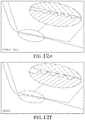
- FIGS. 12( a )-( f ) depict various protrusion profiles of a wrench according to the present invention.
- FIG. 13 (views (a)-(e)) depicts photographs of test samples of a wrench with various protrusions.
- FIGS. 14( a )-( d ) depicts various alternative protrusion patterns in accordance with the present invention.
- FIG. 15 is a bar graph depicting the overall protrusion indentation profiles for a highly loaded wrench according to the invention.
- FIGS. 16 and 17 are illustrations of a wrench according to a preferred embodiment of the invention.
- FIGS. 18 and 18A are partial plan enlarged, detail views of an alternative embodiment of a wrench according to the present invention, with FIG. 18A being an exploded view of a portion of FIG. 18 .
- FIG. 19 is another partial plan view of a portion of a wrench according to an embodiment of the present invention superimposed over a portion of a wrench shown in FIG. 1 , engaging the head of a hexagonal fastener.
- FIG. 2 an enlarged portion of a hexagonal fastener F is shown engaged by a prior art, partially shown open-end wrench 100 according to U.S. Pat. No. 6,907,805 which is incorporated by reference herein in its entirety.
- U.S. Pat. Nos. 7,340,982 and 7,788,994, which also pertain to the aforementioned WRIGHT GRIP® wrench, are also incorporated herein by reference in their entireties.
- Wrench 100 has a head 101 with a pair of fixed jaws 102 and 103 that are connected by a throat 105 . Jaws 102 and 103 , along with throat 105 , define an open-ended fastener-engaging cavity 107 .
- Cavity 107 has an opening 107 A at its forward end which can be slipped on fastener F which may be, for example but not limited to, a nut or a bolt head.
- fastener F which may be, for example but not limited to, a nut or a bolt head.
- the term “open-end” wrench and the like should be understood to cover wrenches with fixed jaws, as are shown in the present figures.
- Each of jaws 102 and 103 has a respective fastener engaging surface 109 and 111 .
- Jaw 102 has a planar section 113 which is parallel with a corresponding planar section 115 of jaw 103 .
- Slightly-outwardly inclined surfaces 117 are angled outwardly at the entrance to cavity 107 on each of jaws 102 and 103 .
- Jaw 102 further has an outwardly diverging curved surface 119 which diverges outwardly from the inner end of planar section 113 towards throat 105 , and on which are provided a set of serrations 123 .
- jaw 103 has a corresponding outwardly diverging curved surface 121 on which are provided a similar set of serrations 125 .
- the serrations are formed by protrusions at the opposing end of each recess between the protrusions (other than the recesses at either end of outwardly diverging curved surfaces 119 and 121 ).
- Wrench 100 When fastener F is engaged by wrench 100 , a pair of rounded rear corners C 1 and C 2 is located in cavity 107 .
- Wrench 100 has a pair of opposing rounded rear corners 124 and 126 which are opposite, respectively, to rear corners C 1 and C 2 of fastener F. There is preferably a clearance between respective rear corners C 1 and C 2 and respective rounded rear corners 124 and 126 of wrench 100 .
- a rearward corner C 3 of fastener F engages throat 105 at an endmost part 105 A of throat 105 .
- Throat 105 is rounded and merges with rear corners 124 and 126 , respectively, in gentle curves.
- Fasteners and fixed jaw wrenches are produced to established standards, which are designed to ensure that the largest fastener that meets specifications for a given nominal size will fit into the smallest wrench of that size. Conversely, the smallest fastener of any nominal size must be gripped and turned by the largest wrench for that size. There will always be some clearance between the fastener and the wrench. The clearance will be minimal with a large fastener and a small wrench and larger with a small fastener and large wrench. The clearance dictates the “free swing” for any given fastener and wrench, i.e., the amount of free rotation of the wrench from the loaded to tightening positions to the opposite or loosening positions. Fastener F has a center of rotation.
- Exemplified wrench 200 has a pair of oppositely disposed equally dimensioned, opposite jaws 202 , 203 .
- Wrench 200 could be, for example, a 9/16 inch size open-end wrench, but the invention will apply to any size of open-end wrench having protrusions as described below along with other features of the invention, including but not limited to 1 ⁇ 4inch, 5/16 inch, 3 ⁇ 8 inch, 7/16 inch, 1 ⁇ 2 inch, 5 ⁇ 8 inch, 11/16 inch, 3 ⁇ 4 inch, 13/16 inch, 7 ⁇ 8 inch, 15/16 inch, 1 inch, 1 1/16 inch, 11 ⁇ 8 inch, 11 ⁇ 4 inch, 1 3/16 inch, and the like.
- Fastener F has six corners as was explained previously with respect to FIG. 1 .
- Wrench 200 has a pair of opposite sets of protrusions 204 and 206 .
- Fastener F is a right hand fastener as mentioned, and is tightened by turning it in the clockwise direction. When wrench 200 is tightening fastener F, protrusions 204 are the driving protrusions. This will be explained further hereinafter.
- WRIGHT GRIP® is believed to be the finest open end wrench available since it was first introduced. Open end wrenches according to the present invention represent yet another innovation, as is explained with reference to FIG. 4 .
- WRIGHT GRIP® wrench 100 is shown as a 9/16 inch size open wrench.
- Jaw 102 from WRIGHT GRIP® wrench 100 is partially shown in FIG. 4 in dotted lines 108 .
- Jaw 202 according to the embodiment of the present invention is partially shown also in FIG. 4 in bold, solid lines 208 .
- Jaws 102 of WRIGHT GRIP® wrench 100 includes set of protrusions 104 including protrusions 110 , 112 , 114 and 116 , but as shown in FIG. 4 , only protrusions 110 and 112 are able to engage the surface of fastener F.
- set of protrusions 204 includes protrusions 210 , 212 , 214 and 216 which all simultaneously engage a surface S of fastener F while in a resting engagement between fastener F and wrench 200 .
- protrusions 110 and 112 which engage fastener F when wrench 100 is turning to tighten fastener F
- protrusions 114 and 116 do not engage fastener F, and are all spaced from a surface S of fastener F.
- protrusions 210 , 212 , 214 and 216 of set of protrusions 204 are aligned much closer together and all engage surface S.
- each crown 210 , 212 , 214 and 216 is also shown to be spaced from each other at a distance in the range of 0.020-0.060 inches.
- set of protrusions 104 is located relatively far from corner C 1
- set of protrusions 204 is relatively close to corner C 1 .
- protrusions 204 and 206 are scalable. In other words, for larger wrenches, the radii will be larger and there may be more protrusions, whereas for smaller wrenches the radii will be smaller and there may be fewer protrusions.
- the number of protrusions can also be dependent on the particular manufacturing method used to fabricate wrench 200 . In other words, it should be understood and appreciated that the dimensions provided above are illustrative to the instant embodiment as shown in the figures. However, it should also be understood that an alternative wrench according to the present invention, for example a wrench 50% larger, would have corresponding dimensions that are 50% larger (i.e., would be scalable).
- a wrench such as a 1 ⁇ 4 inch wrench (or any other wrench smaller than a 3 ⁇ 8 inch wrench) in accordance with the present invention may have only 3 protrusions in each opposing pair of protrusions due to wrench-size limitations.
- a 3 ⁇ 8 inch wrench (and those larger) may have 4 protrusions, or at least 4 protrusions, in each opposing set of protrusions and which are scalable in accordance with the present invention.
- each protrusion of each opposing set of protrusions of a given wrench in accordance with the present invention may be advantageously rotated (or tilted) and configured accordingly to maximize the placement of each protrusion of each opposing set of protrusions of a given innovative wrench relative to the surface of the corresponding fastener and such that each protrusion of each opposing set of protrusions of a given innovative wrench is in contact with the corresponding fastener surface while in a resting state engagement between the innovative wrench and the corresponding fastener.
- at least one protrusion is in at least close proximity with the corresponding fastener surface while in a resting state engagement between the innovative wrench and the corresponding fastener.
- close proximity in this sense is at least 5/1000ths of an inch or less, or in the range of 2/1000ths of an inch- 3/1000ths of an inch.
- a plurality of protrusions are in close proximity with the corresponding fastener surface while in a resting state engagement between the innovative wrench and the corresponding fastener.
- at least one protrusion is in contact with the corresponding fastener surface while in a resting state engagement between the innovative wrench and the corresponding fastener.
- all of the protrusions are in contact with the corresponding fastener surface while in a resting state engagement between the innovative wrench and the corresponding fastener.
- inventive wrench 202 has a set of recesses 218 including individual recesses 220 , 222 , 224 and 226 separating the respective protrusions 210 , 212 , 214 and 216 .
- the radius of inventive wrench 200 equals preferably 0.5273 inches larger than the radius of WRIGHT GRIP® wrench 100 of 0.5016 inches.
- one type of the top of protrusions 214 could be flat as shown in FIG. 4 .
- the plane of the uppermost portions 217 (i.e., crown(s)) of each protrusion 210 , 212 , 214 and 216 in set of protrusions 204 , as illustrated in FIGS. 4 and 7 ) may be slightly angled downwardly towards Corner C 1 when engaged with surface S of fastener F.
- Crowns 217 of each of the set of protrusions 214 are coplanar, and the angle between the plane including crowns 217 and the plane of surface S of fastener F is at an angle ⁇ , which is preferably greater than that for an equal size WRIGHT GRIP® wrench 100 .
- ⁇ is advantageously in the range of 75°-180°, and more particularly in the range of 175°-180° ( FIG. 4 ).
- the protrusions are a very important part of the present invention.
- the protrusions penetrate the fastener which the inventive wrench is turning. Such penetration enhances the gripping of the jaw of the inventive wrench, and enables the turning of fasteners even where the corners of the fastener have been worn down and rounded.
- the radius noted above has been increased over corresponding WRIGHT GRIP® wrenches to improve the profile or definition of the respective protrusions.
- FIG. 5 depicts a failed fastener F, and how exactly the protrusions act on the flats of the fastener.
- one protrusion of the present invention closest to the corner C 1 that has been rounded does not engage protrusion 216 .
- the three protrusions above (i.e. to the right) of the protrusion 216 that does not engage will still carry the load.
- the protrusions start at the very corner of the fastener, and there are fewer of them than with the WRIGHT GRIP® wrench.
- fastener F is at an angle relative to the top surfaces of the protrusions. This provides uneven loading and can cause the wrench to slip on the fastener surface more readily.
- FIG. 5 again shows the superpositions of the prior WRIGHT GRIP® wrench 100 in a partial, detailed illustration in dotted lines and wrench 200 according to an embodiment of the present invention in solid lines.
- Corner C 1 of fastener F has been rounded, and corners C 1 have been deformed as a result of extreme force applied to the opposite end of the open end wrench not according to the present invention.
- WRIGHT GRIP® wrench 100 in the present situation has a protrusion 114 which falls on corner C 1 and contributes to the rounding of corner C 1 .
- a measurement of a particular fastener F for being turned by a 9/16′′ size wrench originally had a diameter 0.634 inches, but was rounded to reduce the diameter by 0.026 inches to 0.608 inches.
- Prior art WRIGHT GRIP® wrench 100 slipped over two corners of fastener F and deformed them until failure, although inventive wrench 200 is nonetheless still able to turn failed fastener F.
- Open end wrench 100 has set of protrusions 104 including protrusions 110 , 112 and 114 . Wrenches 100 and 200 are depicted turning fastener F with corner C 1 . As illustrated, protrusion 114 closest to the corner C 1 of fastener F engages corner C 1 of fastener F and does not “grab” corner F. In fact, protrusion 114 engages and imposes a rounding force on corner C 1 .
- wrench 200 has protrusion 210 , 212 , 214 and 216 , and each of protrusions 210 , 212 and 214 respectively engage side S of fastener F and apply a torque by imposing force on surface S when engaged and turned.
- Protrusion 216 in this instance does not engage corner C 1 at all and does not put a corner-rounding force on corner C 1 .
- Protrusions 210 , 212 and 214 penetrate surface S to a depth proportional to the force applied to the opposite end of wrench 200 .
- a wrench made according to the foregoing embodiment of the invention will not slip from fastener F even under adverse conditions.
- open end wrench 200 has throat 205 for merging jaws 202 and 203 opposite a cavity 207 .
- Wrench 200 has inclined surfaces 217 at the entrance to cavity 207 like surfaces 117 in prior art wrench 100 .
- Open-end wrench 200 has throat 205 which has a uniformly curved surface shown in cross-section by a curve 220 .
- the shape of curve 220 can differ for each size of open-end wrench 200 in a scalable manner as described above. Curve 220 is important because it is at least partly determinative of the timing and area of engagement of the respective individual respective sets of protrusions 204 and 206 depending on the direction of rotation of wrench 200 , and the surface of fastener F.
- curve 220 is at least partly determinative of the location of the area of engagement of each protrusion 210 , 212 and 214 , and the distance of respective areas of engagement of the respective protrusions 210 , 212 and 214 , and corner C.
- FIG. 7 shows a protrusion 221 having a uniform flat crown 217 .
- the protrusion could alternatively have a rounded top.
- FIG. 8 a protrusion 224 is depicted having such a rounded top 226 .
- each flat protrusion top 217 is advantageous in that the pressure put on its top 222 is a generally uniform pressure. This would extend the useful life of sets of protrusions 204 and 206 , but a possible disadvantage is that the penetration is limited into a fastener to be turned, which could limit the amount of torque to be applied to a fastener F.
- the rounded top 226 of protrusion 224 would provide point contact (or contact closer to point contact) which would result in deeper penetration of protrusion 224 into fastener F to increase the torque to be applied to fastener F, but a disadvantage would include a more limited useful life of rounded protrusion 224 as compared to sets of protrusions 204 and 206 with crown shapes due to the wearing down of rounded top 226 , and the unequal force applied by fastener F to protrusion 224 could possibly impair the life of fastener F and protrusion 224 .
- FIG. 9 illustrates a portion of a wrench 300 according to an embodiment of the present invention having a jaw 302 with a set of protrusions 304 .
- Set of protrusions 304 includes five protrusions 306 , 308 , 310 , 312 and 314 as shown therein.
- Protrusion 306 is closest to a surface S of fastener F extending towards a throat T which surface is partly shown in FIG. 9 .
- Each of protrusions 306 , 308 , 310 , 312 and 314 have respective flat crowns 316 , 318 , 320 , 322 and 324 .
- Each of the respective protrusions in set 304 have respective sides 326 , 328 , 330 , 332 and 334 that are curved in cross-section.
- Protrusion 306 has a curved side 336 adjacent to surface S leading to the throat, and the remaining sides 326 , 328 , 330 , 332 and 334 all extend between the respective recesses 338 between each protrusions in set 304 .
- Protrusion 306 has a width greater than that of protrusions 308 , 310 , 312 and 314 , the latter all being of equal widths.
- the technology relating to protrusions, particularly with respect to protrusions on outwardly curved diverging surfaces in open-end wrenches is important with respect to the present invention.
- the wrench turns the fastener (which is often a bolt head or a nut)
- the head of the fastener becomes lodged in the jaw of the wrench closest to the throat.
- the resultant torque applied by the driving jaw of the wrench on the head of fastener increases in proposition to the applied force.
- the protrusions on the driving jaw penetrate the side of the fastener, and this penetration prevents the wrench from slipping.
- the protrusions penetrate the side of the fastener deeper and there is no failure.
- the protrusions along with their angular placement on the jaw of the wrench provide a superior open end wrench to any others of which the inventors are aware with an unmatched design.
- An aspect of the present invention relates to incorporating features in an open-end wrench according to the invention by increasing the maximum torque to the head of the fastener being turned without failure of the wrench.
- the following are at least some of the following features: (1) providing relief of force on the throat of the wrench, rearward of the protrusion adjacent to the throat; (2) lengthening the distance between the protrusions on both jaws of the wrench; (3) increasing the width of the concave region between the respective protrusions (i.e.
- a set of open-end wrenches having a series of wrenches of different sizes for engaging fasteners of corresponding different sizes for applying maximum torque to the fasteners without rounding, spreading or deforming the respective fastener corners.
- the term “fastener” is used herein to cover any item for fastening one piece to another one or more pieces, where the item has a hexagonal or other polygonal cross section, such as (1) a nut including a hexagonal nut, a nylon insert lock, a nylon insert jam lock, a hex nut cap, an acorn incorporating a hex nut, a flange incorporating a hex nut, a square nut and a coupling having a hexagonal cross section, and a thread cutting machine screw with a hexagonal head; (2) a polygonal bolt such as a hex bolt or a flange bolt; and (3) a polygonal washer such as a hex washer or a slotted hex washer.)
- the inventive open end wrench has a pair of a jaws extending from a throat area which is curved in a concave manner away from the opening of the open-end wrench which has a pair of opposing surfaces that face each other (“facing surfaces”) for
- the facing surfaces are generally planar near the open end of the wrench and diverge outwardly away from the central axis of the opened portion between the jaws, and which merge into outwardly diverging curved surfaces, the latter curved surfaces merge into the curved throat portion of the open end wrench.
- the respective outwardly diverging curved surfaces have a set of protrusions which are designed to engage the side of the hexagonal fastener to which a positive force is to be applied, the flat surface of the opposing fastener-engaging surface of the other jaw applies a reactive force to the fastener.
- the outwardly diverging curved surface with the protrusions is designed to apply a force to the fastener which applies a maximum torque to the fastener prior to turning of the wrench to enable an easier and improved turning of the fastener upon the application of a turning force to the open-end wrench.
- the diverging surface with the protrusions is selected so that the protrusions engage the surface of the fastener near, but not on, the corner of the fastener so that each protrusion does not engage and damage the corner of the fastener. Since fasteners come in different sizes, there would be a set of open-end wrenches according to the invention for use with a series of fasteners of different sizes.
- maximum torque is applied to the fasteners regardless of the size of the fastener provided the appropriate open-end wrench according to the invention is selected for use.
- maximum torque is being used herein, but this size for applying the maximum torque is within a certain tolerance since the set of open-wrenches according to the invention would not cover every possible size of fastener, but mainly the sizes of fasteners with which the set of inventive wrenches is to be used.
- Other embodiments of the invention relate to different shapes of the protrusions, different sizes of the protrusions, different locations of the protrusions.
- the clearance between rear corners C 1 and C 2 of fastener F, and rearward corners 124 and 126 of wrench 100 are designed to prevent the engagement of, and rounding of, rearward corners C 1 and C 2 .
- the torque applied by wrench 100 to fastener F upon the application of a turning force to wrench 100 for a fastener having an effective diameter of 3 13/16 inches would apply a force vector to the lever arm L of 0.692 inch.
- FIG. 3 the same fastener F is shown having the same dimensions and shown with the same numerical indicators as with FIG. 2 .
- a wrench according to a preferred embodiment of the invention is shown in FIG. 3 .
- FIG. 3 rather than having an outwardly diverging curved surfaces 119 and 121 extending from the midpoints from the rearwardmost (proximal throat 105 ) ends of outwardly diverging curved surfaces 119 and 121 to the midpoints of rearward curved corners 124 and 126 by the distances 128 and 130 as shown in FIG.
- the distances from the midpoints of the rearwardmost ends of outwardly diverging curved surfaces 228 and 230 extend to the midpoints of rearward curved corners 232 and 234 of wrench 200 by the distances 236 and 238 , substantially less than dimension 128 and 130 in FIG. 2 .
- the most important distance between FIG. 1 and FIG. 2 is that the lever arm (L 2 ) is 0.982 inch in FIG. 3 as compared to the lever arm (L 1 ) in FIG. 2 of 0.692 inch, indicating a much larger lever arm, and maximum torque for the embodiment of the invention shown in FIG. 3 .
- the angle ⁇ for a 9/16 inch size wrench showing the angle of outwardly diverging curved section 32 ′ is from 175° to 180°. This amount increases for larger wrenches according to the invention and decreases for smaller wrenches according to the invention.
- the protrusion profile can be an elongated, tear drop shape.
- the elongated region is due, not only to the compressive or downward force to make the depression, but also to a large shear stress acting to push the material horizontally. It has been noted that in addition to the visual shape of the depression, the resulting radius is of the same shape as that of the concave portion of the protrusion.
- the maximum stressor will be more distributed and will stop deforming further into the head of the fastener. Thus, without further penetration and increased shear stresses on the bolt surface, the material will eventually flow toward the corner of the fastener, and failure may occur there unless the fastener does not fail first.
- FIG. 12 indicates that where the protrusion has a cylindrical shape or a spherical shape, this type of geometry occurs when the protrusion contacts the surface of the fastener. This configuration generates a point loading configuration. This is different than the distributed pressure profile shown in FIG. 11 .
- the point loading orientation particularly in contact mechanics, produces an “infinitely” large initial load. This allows immediate surface penetration. Thus, even at light loading, the profile will start to “grab” onto the fastener head and start embedding into the fastener head surface.
- the last protrusion on the inside of the respective jaws is at the commencement of the throat. It proceeds from the top of the innermost protrusion to the rounded rear corner 234 in FIG. 3 to avoid contact of the fastener with the wrench to allow further penetration of the protrusion into the fastener, resulting in protrusions penetrating deeper into the fastener.
- the inventive concept involves increasing the maximum amount of torque until failure occurs by providing the following:
- the present invention involves an analysis of the changes in the geometry and the determination of the optimal shape of the protrusions used in the present open-end wrenches. This involves a static analysis of the forces acting on the surface of the fastener head as for applying torque to the head. A force body diagram is used to analyse the geometric parameters to the wrench to determine the forces acting thereon.
- Bolt testing was done wherein certain assumptions were made about some parameters and certain assumptions were also made about some properties. There were a total of 6 bolts used for 3 different applied loads and for each protrusion geometry. Therefore a total of 36 test bolts were tested to determine depth data. Bolt depths were accomplished using a Mirco-View visual comparator, which allowed for a quantitative depth determination, but a qualitative view of the bolt surface penetration. A visual image of the protrusion insertion into the bolt surface using the optical comparator can be seen in the side figure of FIG. 11B .
- FIG. 15 presents the overall protrusion indentation profiles for a highly loaded wrench according to the invention.
- a steady 75 ft-lbf torque was applied to the fastener head for 30 seconds.
- both the v1.0 and v2.0 saw maximum penetration into the bolt head.
- the evidence of this is shown in subfigures 13 ( b ) and 13 ( e ), where the material has been shaped to a radius.
- Each identifiable tooth profile has a typical feature, which is an elongated, tear drop shape. The elongated region is not only due to the compressive (downward) force to make the depression, but a large shear stress acting to push the material horizontally.
- the resulting radius at positions 2 and 3 are the same shape as that of the concave portion of the protrusion. It should be noted that when the material reaches the maximum depth of the protrusion, that the maximum stresses will be more distributed and will stop deforming further into the bolt head. Therefore, without further penetration and increased shear stresses on the bolt surface, the material will eventually flow towards the corner of the bolt and that is where failure will occur, if the bolt does not first fail.
- FIG. 11 (A) The formula as shown and depicted in ( FIG. 11 (A) is the force diagram for a 9/16′′ size opening wrench.
- the geometric formula as also shown and depicted in FIG. 11 (A) determines the value of R 2 .
- R 2 F n ⁇ c + b + a ⁇ ⁇ cos ⁇ ⁇ ⁇ c - 1 d c + 1
- R 2 F n + R 2
- the present study compares the prior protrusion profile (v1.0) of the WRIGHT GRIP® wrench against the protrusion profile v2.0 of the present invention.
- Various force loads were applied into the free body diagram geometries for both profiles v1.0 and v2.0 to determine the reaction force R 2 .
- the reaction forces vary in a linear fashion with respect to the applied load as shown in the graph shown and depicted in FIG. 11(B) .
- the reaction force R 2 is used to determine the pressure each protrusion will place on the surface of the head of the fastener.
- the experimental work proceeded as follows.
- the test was made on a 4140 steel housing that was machined to prepare a hole in test bolt.
- the test bolt could be threaded into the prepared fixture.
- the front surface of the bolt was machined.
- the machined hole was drilled and tapped perpendicular to the machined front surface so that the wrench could set flush against the steel fixture.
- the wrench used was a 9/16′′ open-end wrench.
- a load was applied to the 9/16′′ open-end wrench was done with a set of calibrated weights that were fixed to the end of the wrench by a fixture. This was a “dead-hang” set up that allowed for an accurate, constant load applied as the load during each test.
- An angle meter was affixed to the shaft of the wrench to assure proper and accurate loading during each test.
- the associated “normal” applied load force F n was determined for each set of hung weights.
- FIGS. 12( a )-12( e ) depict a v1.0 protrusion profile
- 12 ( b ) depicts a v2.0 protrusion profile
- 12 ( c ) depicts v1.0 overall length and protrusion length and location with respect to the top of the driving jaw
- 12 ( d ) depicts the overall length and protrusion length and location with respect to the top of the driving draw.
- FIG. 12( e ) A depiction is also shown and provided in FIG. 12( e ) of protrusions following tightening of a fastener using a wrench according to the present invention where protrusions are in proper form, and in 12 ( f ) where the protrusions closest to the throat of the wrench are somewhat worn down.
- FIG. 13 having views (a)-(e) is composed of photographs of test samples of the v1.0 and v2.0 protrusion penetration depths for the 75 foot ⁇ pound force loading.
- FIG. 13( a ) is an isometric view of the v1.0 protrusion marks left on Grade 8 bolt head
- FIG. 13( b ) is a side depth profile of the v1.0 protrusion provide
- FIG. 13( c ) is an isometric view of the v2.0 protrusion marks left on the Grade 8 fastener head
- FIG. 13( d ) is the side depth profile
- FIG. 13( c ) is the magnification of the protrusion/fastener head interface of the v1.0 profile.
- FIGS. 14( a ) and 14( c ) respectively show a linearly varying protrusion pattern 400 ( FIG. 14 a ) and a spherical type protrusion geometry 500 ( FIG. 14 c ).
- the linearly varying geometry, FIG. 14( a ) allows for increased material depression since, in reality the forces on each respective tooth is different and each will penetrate the bolt material at a different rate. Additionally, the protrusion “tooth” 410 when touching the bolt material ( 412 ), will produce a uniform pressure over the flat of the tooth.
- FIG. 14( c ) Another type of profile, as shown in FIG. 14( c ) , uses a cylindrical shape/spherical shape protrusion 510 .
- the benefit of this type of geometry occurs when the protrusion contacts the surface of the bolt 512 .
- This configuration will generate a point loading configuration. This is quite different than the distributed pressure profile presented in FIG. 14( a ) .
- the point loading orientation especially in contact mechanics, will produce an “infinitively” large initial load, thus allowing for immediate surface penetration. Therefore, even at light loading, the profile will start to “grab” onto the bolt head and start embedding into the bolt head surface in accordance with the present invention.
- a linearly decreasing protrusion profile and/or a cylindrical shaped protrusion are part of the inventive concept.
- the linearly decreasing protrusion allows the first protrusion to have a deeper cavity initially while the other cavities progressively get shallower. This allows for deeper penetration of the protrusion profiles.
- the second protrusion will exploit the point force and/or line load solution to allow for much deeper initial penetration especially in lightly loaded wrenches.
- FIG. 15 there is a bar graph depicting the overall protrusion indentation profiles for a highly loaded wrench according to the invention.
- FIGS. 16 and 17 A version of the inventive wrench is disclosed in FIGS. 16 and 17 .
- FIG. 16 is a picture of the inventive wrench described as “Wright Grip 2.0,” and two other wrenches made by the Wright Tool Company and a third wrench made by other companies. It can be seen from the bar graph that the inventive wrench has more than 50% of tooth engagement than the previous WRIGHT GRIP® wrench, and 80% more tooth engagement than any other open end wrench made by other companies.
- FIG. 17 is another view of the inventive wrench for the 9/16′′ size. These are indeed remarkable wrenches, providing more strength, higher gripping power and able to turn fasteners whose corners have been rounded down and unable to be turned by prior wrenches known in the art.
- FIGS. 18 and 18A an enlarged and exploded, respectively, representation of a portion of an open-end wrench 600 according to a preferred embodiment of the invention is shown and described.
- wrench 600 has protrusions on one of the working surfaces that would turn to tighten the depicted right hand hexagonal fastener F.
- Exemplified wrench 600 has a pair of oppositely disposed equally dimensioned, opposite jaws 602 , 603 .
- Wrench 600 could be, for example in this instance, a 3 ⁇ 8 inch size open-end wrench.
- Fastener F has six corners as was explained previously with respect to FIG. 1 .
- Wrench 600 has a pair of opposite sets of protrusions 604 and 606 .
- Fastener F is a right hand fastener as mentioned, and is tightened by turning it in the clockwise direction.
- protrusions 606 are the driving protrusions in the same manner as described above.
- set of protrusions 604 includes protrusions 610 , 612 , 614 and 616 which all simultaneously engage a surface S of fastener F while in a resting engagement between fastener F and wrench 600 . Moreover, protrusions 610 , 612 , 614 and 616 of set of protrusions 604 are aligned much closer together and all engage surface S. The distance (D 2 ) from the beginning of a protrusion (protrusion 616 in FIG.
- each crown 610 , 612 , 614 and 616 is also shown to be spaced from each other at a distance in the range of about 0.018 inches.
- set of protrusions 604 is relatively close to corner C 2 .
Landscapes
- Engineering & Computer Science (AREA)
- Mechanical Engineering (AREA)
- Details Of Spanners, Wrenches, And Screw Drivers And Accessories (AREA)
Abstract
Description
4(0.020 in.×0.216 in.)+0.026 in.×0.216 in.=0.0229 in.2
-
- A=overall depth of wrench from tip of opening to end of the throat
- B=depth from tip of opening to endmost part of the throat
- C=depth from end of planar section 30′ to endmost part 19′ of
throat 18′ - D=depth from inner end of outwardly diverging curved surface to endmost part of the throat
- E=distance between planar opposing surfaces of the jaws
- F=distance between the longitudinal center of open-end wrench which intersects with depth D to define the radius for the outer curvature of one of the jaws
- G=distance between the longitudinal center of open-
end wrench 10′ and the axis of rotation for the curve of one of the outwardly diverging curved surfaces - H=the axis of curvature for the respective protuberances and recesses for one of the jaws
- I=the distance from the throat to location H
- α=radius of the throat
- β=radius of curvature for the portion of the throat on opposite sides of endmost part of the throat
- γ=radius of curvature between β and the innermost part of outwardly diverging curved surfaces
- δ=radius of an innermost protrusion
- ε=radius of an outermost recess
- ζ=angle of curvature of an outermost portion of outwardly diverging curved surface 36′
- η=radius of curvature of the sequentially inner portion of outward diverging curved surface
- ι=radius of curvature of the next sequentially portion of outwardly diverging curved surface
- κ=radius of curvature of the next sequentially inner portion of outwardly diverging curved surface
- λ=radius of curvature of the next sequentially inner portion of outwardly diverging curved surface when such radius of curvature exists
- μ=radius of curvature of the inner most portion of outwardly diverging curved surface
- ν=radius of curvature of the rearwardmost radius
- ξ=angle of slightly-inclined surface at the entrance to the cavity of the wrench
-
- a. there is a relief of the wrench throat rearward of the most-rearward protrusion;
- b. lengthening the distance between the protrusions;
- c. increasing the width of the concave region between the protrusions, to increase the area for receiving the portion of the fastener;
- d. providing that the closer the respective protrusions go to point contact reduces the force distribution, i.e. resulting in a decrease in the surface contact of each protrusion;
- e. number of protrusions is increased that engage the fastener; and
- f. the increase in the maximum torque to failure occurs.
Claims (22)
Priority Applications (1)
| Application Number | Priority Date | Filing Date | Title |
|---|---|---|---|
| US16/180,249 US11219985B2 (en) | 2017-11-03 | 2018-11-05 | Wrench for maximizing torque |
Applications Claiming Priority (2)
| Application Number | Priority Date | Filing Date | Title |
|---|---|---|---|
| US201762581088P | 2017-11-03 | 2017-11-03 | |
| US16/180,249 US11219985B2 (en) | 2017-11-03 | 2018-11-05 | Wrench for maximizing torque |
Publications (2)
| Publication Number | Publication Date |
|---|---|
| US20190134787A1 US20190134787A1 (en) | 2019-05-09 |
| US11219985B2 true US11219985B2 (en) | 2022-01-11 |
Family
ID=66328192
Family Applications (1)
| Application Number | Title | Priority Date | Filing Date |
|---|---|---|---|
| US16/180,249 Active 2039-11-20 US11219985B2 (en) | 2017-11-03 | 2018-11-05 | Wrench for maximizing torque |
Country Status (1)
| Country | Link |
|---|---|
| US (1) | US11219985B2 (en) |
Cited By (1)
| Publication number | Priority date | Publication date | Assignee | Title |
|---|---|---|---|---|
| US12533774B2 (en) * | 2023-08-02 | 2026-01-27 | Tsan-Chang Lee | Engaging structure for hand tool |
Families Citing this family (4)
| Publication number | Priority date | Publication date | Assignee | Title |
|---|---|---|---|---|
| US11040432B2 (en) * | 2018-10-19 | 2021-06-22 | Tekton, Inc. | Tool manufacturing method |
| US11780059B2 (en) | 2019-01-23 | 2023-10-10 | Wright Tool Company | Socket wrench opening |
| GB202110519D0 (en) | 2021-07-21 | 2021-09-01 | Buchanan Nigel | Three jaw wrench |
| GB202110511D0 (en) | 2021-07-21 | 2021-09-01 | Buchanan Nigel | Ratcheting open wrench |
Citations (35)
| Publication number | Priority date | Publication date | Assignee | Title |
|---|---|---|---|---|
| GB289703A (en) | 1927-09-27 | 1928-05-03 | Alfred Henry Witter | Improvements in or relating to spanners or wrenches |
| US3003379A (en) | 1958-04-24 | 1961-10-10 | Pribitzer Hans | Open end spanner wrench |
| US3745859A (en) | 1971-09-16 | 1973-07-17 | J Evans | Ratchet-type speed wrench |
| US3757614A (en) | 1971-11-15 | 1973-09-11 | J Evans | Rachet type speed wrench |
| US3850057A (en) | 1973-11-23 | 1974-11-26 | Johnson P | Combination torqueing and ratcheting wrench |
| US3868873A (en) | 1973-04-16 | 1975-03-04 | James P Evans | End wrench with ratcheting capabilities |
| US3931749A (en) | 1973-04-16 | 1976-01-13 | Evans James P | Reversible self-retaining ratcheting wrench |
| US4688454A (en) | 1985-07-26 | 1987-08-25 | The Boeing Company | Open-ended, high torque wrench for use on nuts to which there is limited access |
| US5074171A (en) | 1990-10-29 | 1991-12-24 | Snap-On Tools Corporation | Open-end wrench with reduced size jaws |
| US5117714A (en) | 1989-10-16 | 1992-06-02 | Snap-On Tools Corporation | One-piece, open-end wrenching head with serrated jaws |
| EP0580177A1 (en) | 1992-07-23 | 1994-01-26 | Snap-On Tools Corporation | Speed wrench |
| CN2179808Y (en) | 1993-10-28 | 1994-10-19 | 谢智庆 | Open-end wrench to drive rounded ties |
| US5533428A (en) | 1994-11-21 | 1996-07-09 | Pradelski; William M. | Ratchetable open-ended wrench |
| US5551322A (en) | 1989-07-11 | 1996-09-03 | Snap-On Technologies, Inc. | Speed wrench |
| EP0921912A1 (en) | 1996-08-12 | 1999-06-16 | Serge Simplet | Open end wrench with manual and alternative rotation control |
| US5953968A (en) | 1998-05-15 | 1999-09-21 | Proprietary Technologies, Inc. | Surface conforming, torque enhancing wrench with non-parallel working surfaces |
| US5996449A (en) | 1998-01-23 | 1999-12-07 | Hsieh; Chih-Ching | Open end wrench practical for turning normal and worn-out bolts and nuts of different specifications |
| US6089131A (en) | 1995-06-23 | 2000-07-18 | Facom | Ratcheting wrench for driving an element with a hexagonal head, in particular a bolt or nut |
| US6145414A (en) * | 1998-01-23 | 2000-11-14 | Hsieh; Chih-Ching | Open end wrench for turning normal and worn-out bolts and nuts of different specifications |
| US6276240B1 (en) | 1998-11-09 | 2001-08-21 | Gordon D. Blacklock | Multi-sized, reversible ratcheting action open end wrench |
| FR2807356A1 (en) | 2000-04-07 | 2001-10-12 | Facom | TOOL FOR TRAINING A HEXALOBE ORGAN |
| US6443038B2 (en) | 1998-02-11 | 2002-09-03 | Chin-Ching Hsieh | Open-end wrench for turning normal and worn-out bolts and nuts of different specifications |
| CN2561556Y (en) | 2002-07-24 | 2003-07-23 | 谢智庆 | Wrench structure for piping |
| JP2003340733A (en) | 2002-05-27 | 2003-12-02 | Rin Shutei | Spanner for preventing slip or corner dulling |
| US6907805B2 (en) * | 2002-07-24 | 2005-06-21 | Wright Tool Company | Wrench |
| US20110239831A1 (en) * | 2010-04-05 | 2011-10-06 | Charles Austin Cole | Wrench with wrench head having a planar overhang |
| EP2517831A1 (en) | 2011-04-28 | 2012-10-31 | New Way Tools Co., Ltd. | Open-end wrench for quickly turning an object |
| US20120272794A1 (en) | 2011-04-26 | 2012-11-01 | Ping-Wen Huang | Open-end Wrench for Quickly Turning an Object |
| US20120297936A1 (en) | 2011-05-25 | 2012-11-29 | E-Make Tools Co., Ltd | Open end wrench |
| US8359952B2 (en) * | 2005-06-07 | 2013-01-29 | Chih-Ching Hsieh | Open-end wrench |
| US20130192428A1 (en) | 2011-05-25 | 2013-08-01 | Kung-Cheng Chen | Open end wrench |
| US20130340575A1 (en) * | 2005-06-07 | 2013-12-26 | Kabo Tool Company | Open-End Wrench |
| US8695460B2 (en) | 2012-02-09 | 2014-04-15 | Jia-Guann Liau | Wrench |
| US8973471B2 (en) * | 2011-07-15 | 2015-03-10 | Kabo Tool Company | Three-protuberance open-end wrench |
| US9452511B2 (en) | 2010-11-24 | 2016-09-27 | Last Tool Factory Llc | Combination ER wrench |
-
2018
- 2018-11-05 US US16/180,249 patent/US11219985B2/en active Active
Patent Citations (38)
| Publication number | Priority date | Publication date | Assignee | Title |
|---|---|---|---|---|
| GB289703A (en) | 1927-09-27 | 1928-05-03 | Alfred Henry Witter | Improvements in or relating to spanners or wrenches |
| US3003379A (en) | 1958-04-24 | 1961-10-10 | Pribitzer Hans | Open end spanner wrench |
| US3745859A (en) | 1971-09-16 | 1973-07-17 | J Evans | Ratchet-type speed wrench |
| US3757614A (en) | 1971-11-15 | 1973-09-11 | J Evans | Rachet type speed wrench |
| US3868873A (en) | 1973-04-16 | 1975-03-04 | James P Evans | End wrench with ratcheting capabilities |
| US3931749A (en) | 1973-04-16 | 1976-01-13 | Evans James P | Reversible self-retaining ratcheting wrench |
| US3850057A (en) | 1973-11-23 | 1974-11-26 | Johnson P | Combination torqueing and ratcheting wrench |
| US4688454A (en) | 1985-07-26 | 1987-08-25 | The Boeing Company | Open-ended, high torque wrench for use on nuts to which there is limited access |
| US5551322A (en) | 1989-07-11 | 1996-09-03 | Snap-On Technologies, Inc. | Speed wrench |
| US5117714A (en) | 1989-10-16 | 1992-06-02 | Snap-On Tools Corporation | One-piece, open-end wrenching head with serrated jaws |
| US5074171A (en) | 1990-10-29 | 1991-12-24 | Snap-On Tools Corporation | Open-end wrench with reduced size jaws |
| EP0580177A1 (en) | 1992-07-23 | 1994-01-26 | Snap-On Tools Corporation | Speed wrench |
| CN2179808Y (en) | 1993-10-28 | 1994-10-19 | 谢智庆 | Open-end wrench to drive rounded ties |
| US5533428A (en) | 1994-11-21 | 1996-07-09 | Pradelski; William M. | Ratchetable open-ended wrench |
| US6089131A (en) | 1995-06-23 | 2000-07-18 | Facom | Ratcheting wrench for driving an element with a hexagonal head, in particular a bolt or nut |
| EP0921912A1 (en) | 1996-08-12 | 1999-06-16 | Serge Simplet | Open end wrench with manual and alternative rotation control |
| US6145414A (en) * | 1998-01-23 | 2000-11-14 | Hsieh; Chih-Ching | Open end wrench for turning normal and worn-out bolts and nuts of different specifications |
| US5996449A (en) | 1998-01-23 | 1999-12-07 | Hsieh; Chih-Ching | Open end wrench practical for turning normal and worn-out bolts and nuts of different specifications |
| US6443038B2 (en) | 1998-02-11 | 2002-09-03 | Chin-Ching Hsieh | Open-end wrench for turning normal and worn-out bolts and nuts of different specifications |
| US5953968A (en) | 1998-05-15 | 1999-09-21 | Proprietary Technologies, Inc. | Surface conforming, torque enhancing wrench with non-parallel working surfaces |
| US6276240B1 (en) | 1998-11-09 | 2001-08-21 | Gordon D. Blacklock | Multi-sized, reversible ratcheting action open end wrench |
| FR2807356A1 (en) | 2000-04-07 | 2001-10-12 | Facom | TOOL FOR TRAINING A HEXALOBE ORGAN |
| JP2003340733A (en) | 2002-05-27 | 2003-12-02 | Rin Shutei | Spanner for preventing slip or corner dulling |
| US6907805B2 (en) * | 2002-07-24 | 2005-06-21 | Wright Tool Company | Wrench |
| US7340982B2 (en) | 2002-07-24 | 2008-03-11 | Wright Tool Company | Wrench |
| US7788994B2 (en) | 2002-07-24 | 2010-09-07 | Wright Tool Company | Wrench |
| CN2561556Y (en) | 2002-07-24 | 2003-07-23 | 谢智庆 | Wrench structure for piping |
| US8359952B2 (en) * | 2005-06-07 | 2013-01-29 | Chih-Ching Hsieh | Open-end wrench |
| US8667873B2 (en) | 2005-06-07 | 2014-03-11 | Kabo Tool Company | Open-end wrench |
| US20130340575A1 (en) * | 2005-06-07 | 2013-12-26 | Kabo Tool Company | Open-End Wrench |
| US20110239831A1 (en) * | 2010-04-05 | 2011-10-06 | Charles Austin Cole | Wrench with wrench head having a planar overhang |
| US9452511B2 (en) | 2010-11-24 | 2016-09-27 | Last Tool Factory Llc | Combination ER wrench |
| US20120272794A1 (en) | 2011-04-26 | 2012-11-01 | Ping-Wen Huang | Open-end Wrench for Quickly Turning an Object |
| EP2517831A1 (en) | 2011-04-28 | 2012-10-31 | New Way Tools Co., Ltd. | Open-end wrench for quickly turning an object |
| US20120297936A1 (en) | 2011-05-25 | 2012-11-29 | E-Make Tools Co., Ltd | Open end wrench |
| US20130192428A1 (en) | 2011-05-25 | 2013-08-01 | Kung-Cheng Chen | Open end wrench |
| US8973471B2 (en) * | 2011-07-15 | 2015-03-10 | Kabo Tool Company | Three-protuberance open-end wrench |
| US8695460B2 (en) | 2012-02-09 | 2014-04-15 | Jia-Guann Liau | Wrench |
Cited By (1)
| Publication number | Priority date | Publication date | Assignee | Title |
|---|---|---|---|---|
| US12533774B2 (en) * | 2023-08-02 | 2026-01-27 | Tsan-Chang Lee | Engaging structure for hand tool |
Also Published As
| Publication number | Publication date |
|---|---|
| US20190134787A1 (en) | 2019-05-09 |
Similar Documents
| Publication | Publication Date | Title |
|---|---|---|
| US11219985B2 (en) | Wrench for maximizing torque | |
| US20240075591A1 (en) | Locking Pliers with Movable Torque-Increasing Jaw Section | |
| JP5185931B2 (en) | Load-indicating fastener and method of manufacture | |
| EP3634692B1 (en) | Anti-slip torque tool | |
| US4498825A (en) | Load indicating flange | |
| JP2961377B2 (en) | Adjustment wrench | |
| AU740372B2 (en) | Box wrench and socket wrench having stopper portions for preventing slippage along a nut or a bolt head | |
| US5551322A (en) | Speed wrench | |
| EP0740981A2 (en) | One-piece, open-end wrenching head with serrated jaws | |
| US5092203A (en) | Wrench openings | |
| NL9200420A (en) | SCREWDRIVER SYSTEM. | |
| ZA200601657B (en) | Improved ratchetable open-ended wrench | |
| CA2261087A1 (en) | Cam-lobed salvage tool | |
| US6962099B2 (en) | Open-end adjustable ratcheting wrench | |
| EP1371453A2 (en) | Asymmetric wrench and fastener system | |
| US20130263705A1 (en) | Lockable grip wrench | |
| US20050109171A1 (en) | Fastener and driving tool with retaining blade | |
| US5671644A (en) | Open-ended ratcheting wrench | |
| US5743158A (en) | Hand wrenching tool for removing torque limited fasteners | |
| ZA200406510B (en) | Set screw with rotating point. | |
| AU7263094A (en) | Process and tool for rotating connecting elements, and connecting element used therewith | |
| AU660551B2 (en) | Speed wrench | |
| US12263560B1 (en) | Anchor and release tool | |
| US20220136357A1 (en) | Locking Pin Tool for use with a Locking Pin of a Wellhead | |
| US20060086212A1 (en) | Adjustable wrench |
Legal Events
| Date | Code | Title | Description |
|---|---|---|---|
| AS | Assignment |
Owner name: WRIGHT TOOL COMPANY, OHIO Free format text: ASSIGNMENT OF ASSIGNORS INTEREST;ASSIGNORS:MILLIGAN, KENNETH R.;TAYLOR, TERRY G.;SIGNING DATES FROM 20171102 TO 20181025;REEL/FRAME:047409/0708 |
|
| FEPP | Fee payment procedure |
Free format text: ENTITY STATUS SET TO UNDISCOUNTED (ORIGINAL EVENT CODE: BIG.); ENTITY STATUS OF PATENT OWNER: SMALL ENTITY |
|
| FEPP | Fee payment procedure |
Free format text: ENTITY STATUS SET TO SMALL (ORIGINAL EVENT CODE: SMAL); ENTITY STATUS OF PATENT OWNER: SMALL ENTITY |
|
| STPP | Information on status: patent application and granting procedure in general |
Free format text: DOCKETED NEW CASE - READY FOR EXAMINATION |
|
| STPP | Information on status: patent application and granting procedure in general |
Free format text: NON FINAL ACTION MAILED |
|
| STPP | Information on status: patent application and granting procedure in general |
Free format text: RESPONSE TO NON-FINAL OFFICE ACTION ENTERED AND FORWARDED TO EXAMINER |
|
| STPP | Information on status: patent application and granting procedure in general |
Free format text: NOTICE OF ALLOWANCE MAILED -- APPLICATION RECEIVED IN OFFICE OF PUBLICATIONS |
|
| STPP | Information on status: patent application and granting procedure in general |
Free format text: PUBLICATIONS -- ISSUE FEE PAYMENT VERIFIED |
|
| STCF | Information on status: patent grant |
Free format text: PATENTED CASE |
|
| MAFP | Maintenance fee payment |
Free format text: PAYMENT OF MAINTENANCE FEE, 4TH YR, SMALL ENTITY (ORIGINAL EVENT CODE: M2551); ENTITY STATUS OF PATENT OWNER: SMALL ENTITY Year of fee payment: 4 |