US11219841B2 - Heat exchange device featuring gas-liquid separation - Google Patents
Heat exchange device featuring gas-liquid separation Download PDFInfo
- Publication number
- US11219841B2 US11219841B2 US16/704,723 US201916704723A US11219841B2 US 11219841 B2 US11219841 B2 US 11219841B2 US 201916704723 A US201916704723 A US 201916704723A US 11219841 B2 US11219841 B2 US 11219841B2
- Authority
- US
- United States
- Prior art keywords
- liquid
- phase
- tube
- gaseous
- heat exchange
- Prior art date
- Legal status (The legal status is an assumption and is not a legal conclusion. Google has not performed a legal analysis and makes no representation as to the accuracy of the status listed.)
- Active, expires
Links
- 239000007788 liquid Substances 0.000 title claims abstract description 46
- 238000000926 separation method Methods 0.000 title claims abstract description 29
- 238000009833 condensation Methods 0.000 claims abstract description 81
- 230000005494 condensation Effects 0.000 claims abstract description 81
- 239000007791 liquid phase Substances 0.000 claims abstract description 66
- 230000017525 heat dissipation Effects 0.000 claims abstract description 63
- 239000007792 gaseous phase Substances 0.000 claims abstract description 52
- 238000001704 evaporation Methods 0.000 claims abstract description 23
- 230000008020 evaporation Effects 0.000 claims abstract description 23
- 239000007789 gas Substances 0.000 claims abstract description 11
- 238000004891 communication Methods 0.000 claims abstract description 10
- 239000012530 fluid Substances 0.000 claims description 45
- XAGFODPZIPBFFR-UHFFFAOYSA-N aluminium Chemical compound [Al] XAGFODPZIPBFFR-UHFFFAOYSA-N 0.000 claims description 14
- 229910052782 aluminium Inorganic materials 0.000 claims description 14
- RYGMFSIKBFXOCR-UHFFFAOYSA-N Copper Chemical compound [Cu] RYGMFSIKBFXOCR-UHFFFAOYSA-N 0.000 claims description 8
- 229910052802 copper Inorganic materials 0.000 claims description 8
- 239000010949 copper Substances 0.000 claims description 8
- 238000001125 extrusion Methods 0.000 claims description 4
- 238000001816 cooling Methods 0.000 description 5
- 230000000694 effects Effects 0.000 description 4
- 230000005484 gravity Effects 0.000 description 4
- 238000012545 processing Methods 0.000 description 3
- 238000007789 sealing Methods 0.000 description 3
- 238000010521 absorption reaction Methods 0.000 description 2
- 230000008859 change Effects 0.000 description 2
- 238000000034 method Methods 0.000 description 2
- 239000012071 phase Substances 0.000 description 2
- 230000009467 reduction Effects 0.000 description 2
- 238000013473 artificial intelligence Methods 0.000 description 1
- 238000007796 conventional method Methods 0.000 description 1
- 125000004122 cyclic group Chemical group 0.000 description 1
- 230000002708 enhancing effect Effects 0.000 description 1
- 238000004880 explosion Methods 0.000 description 1
- 230000006872 improvement Effects 0.000 description 1
- 239000000463 material Substances 0.000 description 1
- 238000012986 modification Methods 0.000 description 1
- 230000004048 modification Effects 0.000 description 1
- 230000002035 prolonged effect Effects 0.000 description 1
- 230000003014 reinforcing effect Effects 0.000 description 1
- 238000012546 transfer Methods 0.000 description 1
Images


Classifications
-
- B—PERFORMING OPERATIONS; TRANSPORTING
- B01—PHYSICAL OR CHEMICAL PROCESSES OR APPARATUS IN GENERAL
- B01D—SEPARATION
- B01D5/00—Condensation of vapours; Recovering volatile solvents by condensation
- B01D5/0003—Condensation of vapours; Recovering volatile solvents by condensation by using heat-exchange surfaces for indirect contact between gases or vapours and the cooling medium
- B01D5/0015—Plates
-
- B—PERFORMING OPERATIONS; TRANSPORTING
- B01—PHYSICAL OR CHEMICAL PROCESSES OR APPARATUS IN GENERAL
- B01D—SEPARATION
- B01D19/00—Degasification of liquids
- B01D19/0063—Regulation, control including valves and floats
-
- B—PERFORMING OPERATIONS; TRANSPORTING
- B01—PHYSICAL OR CHEMICAL PROCESSES OR APPARATUS IN GENERAL
- B01D—SEPARATION
- B01D19/00—Degasification of liquids
- B01D19/0073—Degasification of liquids by a method not covered by groups B01D19/0005 - B01D19/0042
-
- F—MECHANICAL ENGINEERING; LIGHTING; HEATING; WEAPONS; BLASTING
- F28—HEAT EXCHANGE IN GENERAL
- F28D—HEAT-EXCHANGE APPARATUS, NOT PROVIDED FOR IN ANOTHER SUBCLASS, IN WHICH THE HEAT-EXCHANGE MEDIA DO NOT COME INTO DIRECT CONTACT
- F28D1/00—Heat-exchange apparatus having stationary conduit assemblies for one heat-exchange medium only, the media being in contact with different sides of the conduit wall, in which the other heat-exchange medium is a large body of fluid, e.g. domestic or motor car radiators
- F28D1/02—Heat-exchange apparatus having stationary conduit assemblies for one heat-exchange medium only, the media being in contact with different sides of the conduit wall, in which the other heat-exchange medium is a large body of fluid, e.g. domestic or motor car radiators with heat-exchange conduits immersed in the body of fluid
- F28D1/04—Heat-exchange apparatus having stationary conduit assemblies for one heat-exchange medium only, the media being in contact with different sides of the conduit wall, in which the other heat-exchange medium is a large body of fluid, e.g. domestic or motor car radiators with heat-exchange conduits immersed in the body of fluid with tubular conduits
- F28D1/047—Heat-exchange apparatus having stationary conduit assemblies for one heat-exchange medium only, the media being in contact with different sides of the conduit wall, in which the other heat-exchange medium is a large body of fluid, e.g. domestic or motor car radiators with heat-exchange conduits immersed in the body of fluid with tubular conduits the conduits being bent, e.g. in a serpentine or zig-zag
- F28D1/0475—Heat-exchange apparatus having stationary conduit assemblies for one heat-exchange medium only, the media being in contact with different sides of the conduit wall, in which the other heat-exchange medium is a large body of fluid, e.g. domestic or motor car radiators with heat-exchange conduits immersed in the body of fluid with tubular conduits the conduits being bent, e.g. in a serpentine or zig-zag the conduits having a single U-bend
- F28D1/0476—Heat-exchange apparatus having stationary conduit assemblies for one heat-exchange medium only, the media being in contact with different sides of the conduit wall, in which the other heat-exchange medium is a large body of fluid, e.g. domestic or motor car radiators with heat-exchange conduits immersed in the body of fluid with tubular conduits the conduits being bent, e.g. in a serpentine or zig-zag the conduits having a single U-bend the conduits having a non-circular cross-section
-
- F—MECHANICAL ENGINEERING; LIGHTING; HEATING; WEAPONS; BLASTING
- F28—HEAT EXCHANGE IN GENERAL
- F28D—HEAT-EXCHANGE APPARATUS, NOT PROVIDED FOR IN ANOTHER SUBCLASS, IN WHICH THE HEAT-EXCHANGE MEDIA DO NOT COME INTO DIRECT CONTACT
- F28D1/00—Heat-exchange apparatus having stationary conduit assemblies for one heat-exchange medium only, the media being in contact with different sides of the conduit wall, in which the other heat-exchange medium is a large body of fluid, e.g. domestic or motor car radiators
- F28D1/02—Heat-exchange apparatus having stationary conduit assemblies for one heat-exchange medium only, the media being in contact with different sides of the conduit wall, in which the other heat-exchange medium is a large body of fluid, e.g. domestic or motor car radiators with heat-exchange conduits immersed in the body of fluid
- F28D1/04—Heat-exchange apparatus having stationary conduit assemblies for one heat-exchange medium only, the media being in contact with different sides of the conduit wall, in which the other heat-exchange medium is a large body of fluid, e.g. domestic or motor car radiators with heat-exchange conduits immersed in the body of fluid with tubular conduits
- F28D1/053—Heat-exchange apparatus having stationary conduit assemblies for one heat-exchange medium only, the media being in contact with different sides of the conduit wall, in which the other heat-exchange medium is a large body of fluid, e.g. domestic or motor car radiators with heat-exchange conduits immersed in the body of fluid with tubular conduits the conduits being straight
- F28D1/0535—Heat-exchange apparatus having stationary conduit assemblies for one heat-exchange medium only, the media being in contact with different sides of the conduit wall, in which the other heat-exchange medium is a large body of fluid, e.g. domestic or motor car radiators with heat-exchange conduits immersed in the body of fluid with tubular conduits the conduits being straight the conduits having a non-circular cross-section
- F28D1/05366—Assemblies of conduits connected to common headers, e.g. core type radiators
- F28D1/05383—Assemblies of conduits connected to common headers, e.g. core type radiators with multiple rows of conduits or with multi-channel conduits
-
- F—MECHANICAL ENGINEERING; LIGHTING; HEATING; WEAPONS; BLASTING
- F28—HEAT EXCHANGE IN GENERAL
- F28D—HEAT-EXCHANGE APPARATUS, NOT PROVIDED FOR IN ANOTHER SUBCLASS, IN WHICH THE HEAT-EXCHANGE MEDIA DO NOT COME INTO DIRECT CONTACT
- F28D15/00—Heat-exchange apparatus with the intermediate heat-transfer medium in closed tubes passing into or through the conduit walls ; Heat-exchange apparatus employing intermediate heat-transfer medium or bodies
- F28D15/02—Heat-exchange apparatus with the intermediate heat-transfer medium in closed tubes passing into or through the conduit walls ; Heat-exchange apparatus employing intermediate heat-transfer medium or bodies in which the medium condenses and evaporates, e.g. heat pipes
- F28D15/0266—Heat-exchange apparatus with the intermediate heat-transfer medium in closed tubes passing into or through the conduit walls ; Heat-exchange apparatus employing intermediate heat-transfer medium or bodies in which the medium condenses and evaporates, e.g. heat pipes with separate evaporating and condensing chambers connected by at least one conduit; Loop-type heat pipes; with multiple or common evaporating or condensing chambers
-
- F—MECHANICAL ENGINEERING; LIGHTING; HEATING; WEAPONS; BLASTING
- F28—HEAT EXCHANGE IN GENERAL
- F28D—HEAT-EXCHANGE APPARATUS, NOT PROVIDED FOR IN ANOTHER SUBCLASS, IN WHICH THE HEAT-EXCHANGE MEDIA DO NOT COME INTO DIRECT CONTACT
- F28D9/00—Heat-exchange apparatus having stationary plate-like or laminated conduit assemblies for both heat-exchange media, the media being in contact with different sides of a conduit wall
- F28D9/0062—Heat-exchange apparatus having stationary plate-like or laminated conduit assemblies for both heat-exchange media, the media being in contact with different sides of a conduit wall the conduits for one heat-exchange medium being formed by spaced plates with inserted elements
-
- F—MECHANICAL ENGINEERING; LIGHTING; HEATING; WEAPONS; BLASTING
- F28—HEAT EXCHANGE IN GENERAL
- F28F—DETAILS OF HEAT-EXCHANGE AND HEAT-TRANSFER APPARATUS, OF GENERAL APPLICATION
- F28F1/00—Tubular elements; Assemblies of tubular elements
- F28F1/02—Tubular elements of cross-section which is non-circular
- F28F1/022—Tubular elements of cross-section which is non-circular with multiple channels
Definitions
- the present invention relates to a gas-liquid heat exchanger. More particularly, the invention relates to a heat exchange device that features gas-liquid separation and is suitable for use in an electronic product, wherein the gas-liquid separation is achieved by separating the path of a working gas from that of a working liquid.
- a CPU generates a considerable amount of heat during operation. If the heat cannot be effectively dissipated, the CPU will be overheated, and the electronic product using the CPU may eventually slow down or even stop working as a result. The high temperature of the overheated CPU may also damage the neighboring electronic components over time such that the service life of the electronic product is cut short. It is therefore imperative to install a heat dissipation device where the electronic product generates most of the heat, in order for the heat dissipation device to dissipate the heat (i.e., to cool the electronic product) rapidly through thermal conduction or convection, thereby protecting the electronic product and maintaining its normal operation.
- One typical technique for cooling the CPU of an electronic product is to provide the electronic product with a built-in fan, the objective being to generate an airflow that helps bring down the temperature of the CPU; however, the cooling effect of the fan is quite limited when ambient temperature is high. Considering that the conventional CPU cooling methods still leave room for improvement, the inventor of the present invention thought it necessary to devise a novel method for cooling a CPU effectively.
- the primary objective of the present invention is to provide a heat exchange device that features gas-liquid separation and is suitable for use in an electronic product.
- the present invention provides a heat exchange device featuring gas-liquid separation, comprising an evaporator unit and a condenser unit.
- the evaporator unit comprises a housing, an evaporation chamber provided in the housing, and a gas outlet provided at a top side of the evaporation chamber.
- the condenser unit comprises a central main guide tube, a plurality of condensation tubes connected to the central main guide tube, and a heat dissipation fin assembly provided on a periphery of each condensation tube.
- the central main guide tube comprises a gaseous-phase confluence chamber and a liquid-phase confluence chamber.
- the gaseous-phase confluence chamber is provided in an upper portion of the central main guide tube and communicates with the gas outlet through a gaseous-phase connection tube
- the liquid-phase confluence chamber is provided in a lower portion of the central main guide tube and communicates with the evaporation chamber through a liquid-phase connection tube.
- the condensation tubes are connected to two lateral sides of the central main guide tube in pairs, and each condensation tube comprises a first communicating section in communication with the gaseous-phase confluence chamber, a bent section bent downward from the first communicating section, and a second communicating section connecting the bent section to the liquid-phase confluence chamber.
- the present invention also provides a heat exchange device featuring gas-liquid separation, comprising an evaporator unit and a condenser unit.
- the evaporator unit comprises a housing, an evaporation chamber provided in the housing, and a gas outlet provided at a top side of the evaporation chamber.
- the condenser unit comprises a first-side main guide tube, a second-side main guide tube, at least one condensation tube, and a heat dissipation fin assembly provided on a periphery of the condensation tube.
- the condensation tube has two ends connected respectively to the first-side main guide tube and the second-side main guide tube.
- the first-side main guide tube comprises a gaseous-phase confluence chamber in communication with the gas outlet through a gaseous-phase connection tube
- the second-side main guide tube comprises a liquid-phase confluence chamber in communication with the evaporation chamber through a liquid-phase connection tube.
- the heat dissipation fin assembly is composed of a plurality of recumbent square U-shaped fins that are sequentially connected in a head-to-tail manner, or is an integrated wavy fin assembly extruded through rollers or stamping.
- the heat dissipation fin assembly and the condensation tubes are made of aluminum and/or copper.
- first-side main guide tube and the second-side main guide tube respectively include a tube body, a sealing cap provided at one end of the tube body, and a connecting cap provided at the other end of the tube body.
- the housing is provided with a heat dissipation cover, which covers a portion of the gaseous-phase connection tube and is made of aluminum or copper; and, the heat dissipation cover is composed of a plurality of recumbent square U-shaped fins that are sequentially connected in a head-to-tail manner, or is an integrated wavy fin assembly extruded through rollers or stamping.
- the position at which the gaseous-phase connection tube is connected to the housing is higher than the position at which the liquid-phase connection tube is connected to the housing.
- gaseous-phase connection tube has a larger tube diameter than the liquid-phase connection tube.
- condensation tube is made by an aluminum extrusion means and has a flattened cross section.
- condensation tube is provided therein with a plurality of supporting ribs.
- the inner wall of the condensation tube and the surface of each supporting rib are respectively provided with a plurality of microstructures.
- gaseous-phase confluence chamber and the liquid-phase confluence chamber are separately provided to separate the working path of the gaseous-phase working fluid from that of the liquid-phase working fluid, thereby eliminating the impedance the liquid-phase working fluid may otherwise experience when flowing back.
- the evaporator unit and the condenser unit are separately provided and are connected by the gaseous-phase connection tube and the liquid-phase connection tube, the evaporator unit lies compliantly on an external electronic device, and the condenser unit is disposed adjacent to an external fan to receive a largest possible airflow to enhance heat dissipation efficiency.
- the present invention has the following advantages:
- the present invention provides a heat exchange device that features gas-liquid separation. More specifically, the condenser unit of the heat exchange device is provided with a central main guide tube (or two lateral main guide tubes) that separates (or separate) the working path of the gaseous-phase working fluid from that of the liquid-phase working fluid, thereby solving the prior art problem that the returning liquid-phase working fluid tends to be impeded and thus result in a reduction in heat dissipation efficiency.
- the separately provided condenser unit and evaporator unit are connected by a gaseous-phase connection tube and a liquid-phase connection tube that allow the condenser unit to be disposed adjacent to an external fan in order to receive the largest airflow possible, thereby enhancing the heat dissipation efficiency at the evaporation end as well as the condensation end to rapidly cool the external electronic device to which the evaporator unit is applied.
- FIG. 1 is a first perspective view of the heat exchange device featuring gas-liquid separation according to the first embodiment of the present invention.
- FIG. 2 is a second perspective view of the heat exchange device featuring gas-liquid separation according to the first embodiment of the present invention.
- FIG. 3 is a first sectional view of the heat exchange device featuring gas-liquid separation according to the first embodiment of the present invention.
- FIG. 4 is a second sectional view of the heat exchange device featuring gas-liquid separation according to the first embodiment of the present invention.
- FIG. 5 shows the condensation tube of the present invention in partial perspective view.
- FIG. 6 is a first partial enlarged view of the condensation tube of the present invention.
- FIG. 7 is a second partial enlarged view of the condensation tube of the present invention.
- FIG. 8 is a first perspective view of the heat exchange device featuring gas-liquid separation according to the second embodiment of the present invention.
- FIG. 9 is a second perspective view of the heat exchange device featuring gas-liquid separation according to the second embodiment of the present invention.
- FIG. 10 is a first sectional view of the heat exchange device featuring gas-liquid separation according to the second embodiment of the present invention.
- FIG. 11 is a second sectional view of the heat exchange device featuring gas-liquid separation according to the second embodiment of the present invention.
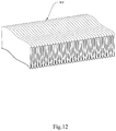
- FIG. 12 is a perspective view of the heat dissipation cover and the heat dissipation fin assembly according to another embodiment of the present invention.
- FIG. 1 and FIG. 2 Please refer to FIG. 1 and FIG. 2 for two perspective views of the heat exchange device featuring gas-liquid separation according to the first embodiment of the present invention.
- the present invention discloses a heat exchange device 100 featuring gas-liquid separation (hereinafter referred to as the gas-liquid separated heat exchange device 100 ) as shown in FIG. 1 and FIG. 2 .
- the gas-liquid separated heat exchange device 100 is configured for use mainly in the fields of optics, communications, data processing, servers, and so on where high-heat laminated circuits are generally required.
- the invention can be applied to such electronic products as servers, data displays, remote radio units (RRUs) for communication purposes, artificial intelligence (AI) devices, display chips, and laser chips to produce a cooling/heat dissipation effect through conduction-, convection-, or material-based heat exchange.
- the gas-liquid separated heat exchange device 100 is advantageously compact and efficient in heat dissipation and is therefore suitable for use in an electronic product with a limited internal mounting space.
- the gas-liquid separated heat exchange device 100 includes an evaporator unit 10 A and a condenser unit 20 A.
- a gaseous-phase connection tube T 1 A and a liquid-phase connection tube T 2 A are provided between the evaporator unit 10 A and the condenser unit 20 A to connect the two units together.
- a working fluid is circulated through the two units while undergoing a cyclic change of phase, which occurs when the working fluid is changed between a heat-absorbing state and a heat-releasing state.
- the phase change helps cool down the electronic product to which the gas-liquid separated heat exchange device 100 is applied, lest the electronic components of the product be damaged, or the performance of the product be lowered, by prolonged exposure to high heat.
- FIG. 3 and FIG. 4 Please refer to FIG. 3 and FIG. 4 for two sectional views of the gas-liquid separated heat exchange device shown in FIG. 1 and FIG. 2 .
- the evaporator unit 10 A includes a housing 11 A, an evaporation chamber 12 A provided in the housing 11 A, and a gas outlet 13 A provided at the top side of the evaporation chamber 12 A.
- the housing 11 A is provided with a heat dissipation cover 14 A, which covers a portion of the gaseous-phase connection tube T 1 A.
- the heat dissipation cover 14 A is made of aluminum or copper and is composed of a plurality of recumbent square U-shaped fins 141 A that are sequentially connected in a head-to-tail manner.
- the gaps between the recumbent square U-shaped fins 141 A form a plurality of airflow channels 142 A that allow passage of air.
- the width of each airflow channel 142 A may range from 0.8 mm to 2 mm to increase the area of contact between the evaporator unit 10 A and air and thereby enhance heat dissipation.
- the evaporation chamber 12 A is provided therein with a plurality of fins 15 A.
- the fins 15 A are integrally formed on the housing 11 A by a relieving means and each have a thickness ranging from 0.2 mm to 1 mm to facilitate heat exchange between the fins 15 A and the liquid-phase working fluid.
- the gaps between the fins 15 A form a plurality of liquid channels to allow passage of the liquid-phase working fluid.
- the gaps between the fins 15 A may range from 0.2 mm to 1 mm to enable sufficient contact, and hence heat exchange, between the liquid-phase working fluid and the fins 15 A.
- the evaporation chamber 12 A includes a first vapor chamber 121 A, which accommodates the fins 15 A, and a second vapor chamber 122 A, which lies above and communicates with the first vapor chamber 121 A.
- the space in the second vapor chamber 122 A is smaller than that in the first vapor chamber 121 A to effect an increase in speed of the working fluid.
- the condenser unit 20 A includes a central main guide tube 21 A, at least one condensation tube 22 A connected to the central main guide tube 21 A (a plurality of condensation tubes 22 A being provided in this embodiment by way example), and a heat dissipation fin assembly 23 A provided on the peripheries of the condensation tubes 22 A.
- the heat dissipation fin assembly 23 A and the condensation tubes 22 A are made of aluminum or copper and are soldered together to avoid gaps in the connected surfaces between the heat dissipation fin assembly 23 A and the condensation tubes 22 A, the goal being to achieve better thermal conduction through tighter connection between the heat dissipation fin assembly 23 A and the condensation tubes 22 A.
- the heat dissipation fin assembly 23 A and the condensation tubes 22 A are preferably made of aluminum.
- the heat dissipation fin assembly 23 A is composed of a plurality of recumbent square U-shaped fins 231 A that are sequentially connected in a head-to-tail manner.
- the gaps between the recumbent square U-shaped fins 231 A form a plurality of airflow channels 232 A that allow passage of air.
- the width of each airflow channel 232 A may range from 0.8 mm to 2 mm to increase the area of contact between the condenser unit 20 A and air and thereby enhance heat dissipation.
- the portion of the heat dissipation fin assembly 23 A that lies beneath the condensation tubes 22 A is higher than the portion of the heat dissipation fin assembly 23 A that lies on top of the condensation tubes 22 A, and the bottom side of the condenser unit 20 A has a larger contact area than the bottom side of the evaporator unit 10 A, in order to achieve highly efficient heat dissipation.
- the central main guide tube 21 A includes a gaseous-phase confluence chamber 211 A and a liquid-phase confluence chamber 212 A.
- the gaseous-phase confluence chamber 211 A is provided in an upper portion of the central main guide tube 21 A and communicates with the gas outlet 13 A through the gaseous-phase connection tube T 1 A.
- the liquid-phase confluence chamber 212 A is provided in a lower portion of the central main guide tube 21 A and communicates with the evaporation chamber 12 A through the liquid-phase connection tube T 2 A.
- the gaseous-phase confluence chamber 211 A and the liquid-phase confluence chamber 212 A are separately provided to separate the working path of the gaseous-phase working fluid from that of the liquid-phase working fluid, thereby eliminating the impedance the liquid-phase working fluid may otherwise experience when flowing back, lest such impedance reduce heat dissipation efficiency.
- the evaporator unit 10 A and the condenser unit 20 A are also separately provided and are connected by the gaseous-phase connection tube T 1 A and the liquid-phase connection tube T 2 A.
- the evaporator unit 10 A is designed to lie compliantly on an electronic device.
- the condenser unit 20 A can be disposed adjacent to a fan in order to receive the largest airflow possible to enhance the heat dissipation efficiency at the evaporation end as well as the condensation end.
- the position at which the gaseous-phase connection tube T 1 A is connected to the housing 11 A is higher than the position at which the liquid-phase connection tube T 2 A is connected to the housing 11 A.
- This arrangement not only allows the evaporator unit 10 A to receive the liquid-phase working fluid with ease, but also uses the gravity of the liquid-phase working fluid to produce a siphoning force that causes circulation of the working fluid, thereby enabling the gas-liquid separated heat exchange device 100 to operate continuously without being driven by an electromechanical means.
- the gaseous-phase connection tube T 1 A has a larger tube diameter than the liquid-phase connection tube T 2 A to make it easier for the force of gravity acting on the liquid-phase working fluid to drive the gas-liquid separated heat exchange device 100 into continuous operation.
- the condensation tubes 22 A are connected to the two lateral sides of the central main guide tube 21 A in pairs and each include a first communicating section 221 A in communication with the gaseous-phase confluence chamber 211 A, a bent section 222 A bent downward from the first communicating section 221 A, and a second communicating section 223 A connecting the bent section 222 A to the liquid-phase confluence chamber 212 A.
- the condensation tubes 22 A with the bent sections 222 A bring the gaseous-phase confluence chamber 211 A and the liquid-phase confluence chamber 212 A into communication with each other.
- FIG. 5 to FIG. 7 show three embodiments of the condensation tube of the present invention in partial perspective view, with FIG. 6 and FIG. 7 providing additional partial enlarged views for two of the embodiments.
- the condensation tube 22 A is made by an aluminum extrusion means so that the integrally formed condensation tube 22 A can withstand the high pressure generated by the working fluid passing through the condensation tube.
- the condensation tube 22 A has a flattened cross section, preferably of a height ranging from 1 mm to 2 mm to facilitate passage of the working fluid and enable sufficient heat absorption by the working fluid, and preferably of a width ranging from 12 mm to 40 mm to provide a relatively large heat dissipation area and thereby enhance contact, and hence heat exchange, with air and the heat dissipation fin assembly 23 A.
- the condensation tube 22 A is provided therein with a plurality of supporting ribs 224 A.
- the supporting ribs 224 A extend along the entire length of the condensation tube 22 A.
- the number of the supporting ribs 224 A may range from the value of one third of the width (in millimeter) of the condensation tube 22 A to the value of the full width (in millimeter) of the condensation tube 22 A.
- the width of the condensation tube 22 A is 12 mm
- the inner wall of the condensation tube 22 A and the surface of each supporting rib 224 A may be flat (as shown in FIG. 5 ) or provided with a plurality of microstructures, wherein the microstructures may be serrated structures 225 A (as shown in FIG.
- wavy structures 226 A as shown in FIG. 7
- web-like, fiber-like, grooved, or sintered capillary structures in order to increase the area of contact between the interior of the condensation tube 22 A and the working fluid and thereby enhance the efficiency of heat dissipation.
- FIG. 8 to FIG. 11 Please refer to FIG. 8 to FIG. 11 for two perspective views and two sectional views of the gas-liquid separated heat exchange device according to the second embodiment of the present invention.
- the gas-liquid separated heat exchange device 200 includes an evaporator unit 10 B and a condenser unit 20 B.
- a gaseous-phase connection tube T 1 B and a liquid-phase connection tube T 2 B are provided between the evaporator unit 10 B and the condenser unit 20 B to connect the two units together.
- the evaporator unit 10 B includes a housing 11 B, an evaporation chamber 12 B provided in the housing 11 B, and a gas outlet 13 B provided at the top side of the evaporation chamber 12 B.
- the housing 11 B is provided with a heat dissipation cover 14 B, which covers a portion of the gaseous-phase connection tube T 1 B.
- the heat dissipation cover 14 B is made of aluminum or copper and is composed of a plurality of recumbent square U-shaped fins 141 B that are sequentially connected in a head-to-tail manner.
- the gaps between the recumbent square U-shaped fins 141 B form a plurality of airflow channels 142 B that allow passage of air.
- the width of each airflow channel 142 B may range from 0.8 mm to 2 mm to increase the area of contact between the evaporator unit 10 B and air and thereby enhance heat dissipation.
- the evaporation chamber 12 B is provided therein with a plurality of fins 15 B.
- the fins 15 B are integrally formed on the housing 11 B by a relieving means and each have a thickness ranging from 0.2 mm to 1 mm to facilitate heat exchange between the fins 15 B and the liquid-phase working fluid.
- the gaps between the fins 15 B form a plurality of liquid channels to allow passage of the liquid-phase working fluid.
- the gaps between the fins 15 B may range from 0.2 mm to 1 mm to enable sufficient contact, and hence heat exchange, between the liquid-phase working fluid and the fins 15 B.
- the evaporation chamber 12 B includes a first vapor chamber 121 B, which accommodates the fins 15 B, and a second vapor chamber 122 B, which lies above and communicates with the first vapor chamber 121 B.
- the space in the second vapor chamber 122 B is smaller than that in the first vapor chamber 121 B to effect an increase in speed of the working fluid.
- the condenser unit 20 B includes a first-side main guide tube 21 B, a second-side main guide tube 22 B, at least one condensation tube 23 B (a plurality of condensation tubes 23 B being provided in this embodiment by way example), and a heat dissipation fin assembly 24 B provided on the peripheries of the condensation tubes 23 B, wherein each condensation tube 23 B has two ends connected respectively to the first-side main guide tube 21 B and the second-side main guide tube 22 B.
- the heat dissipation fin assembly 24 B and the condensation tubes 23 B are made of aluminum or copper and are soldered together to avoid gaps in the connected surfaces between the heat dissipation fin assembly 24 B and the condensation tubes 23 B, the goal being to achieve better thermal conduction through tighter connection between the heat dissipation fin assembly 24 B and the condensation tubes 23 B.
- the heat dissipation fin assembly 24 B and the condensation tubes 23 B are preferably made of aluminum.
- the heat dissipation fin assembly 24 B is composed of a plurality of recumbent square U-shaped fins 241 B that are sequentially connected in a head-to-tail manner.
- the gaps between the recumbent square U-shaped fins 241 B form a plurality of airflow channels 242 B that allow passage of air.
- the width of each airflow channel 242 B may range from 0.8 mm to 2 mm to increase the area of contact between the condenser unit 20 B and air and thereby enhance heat dissipation.
- the portion of the heat dissipation fin assembly 24 B that lies beneath the condensation tubes 23 B is higher than the portion of the heat dissipation fin assembly 24 B that lies on top of the condensation tubes 23 B, and the bottom side of the condenser unit 20 B has a larger contact area than the bottom side of the evaporator unit 10 B, in order to achieve highly efficient heat dissipation.
- the first-side main guide tube 21 B includes a tube body 211 B, a sealing cap 212 B provided at one end of the tube body 211 B, and a connecting cap 213 B provided at the other end of the tube body 211 B.
- the tube body 211 B includes a gaseous-phase confluence chamber 214 B, which communicates with the gaseous-phase connection tube T 1 B through the connecting cap 213 B.
- the second-side main guide tube 22 B includes a tube body 221 B, a sealing cap 222 B provided at one end of the tube body 221 B, and a connecting cap 223 B provided at the other end of the tube body 221 B.
- the tube body 221 B includes a liquid-phase confluence chamber 224 B, which communicates with the liquid-phase connection tube T 2 B through the connecting cap 223 B.
- the first-side main guide tube 21 B and the second-side main guide tube 22 B are connected by the condensation tubes 23 B such that the gaseous-phase confluence chamber 214 B and the liquid-phase confluence chamber 224 B are in communication with each other.
- the gaseous-phase confluence chamber 214 B and the liquid-phase confluence chamber 224 B are separately provided to separate the working path of the gaseous-phase working fluid from that of the liquid-phase working fluid, thereby eliminating the impedance the liquid-phase working fluid may otherwise experience when flowing back, lest such impedance reduce heat dissipation efficiency.
- the evaporator unit 10 B and the condenser unit 20 B are also separately provided and are connected by the gaseous-phase connection tube T 1 B and the liquid-phase connection tube T 2 B.
- the evaporator unit 10 B is designed to lie compliantly on an electronic device.
- the condenser unit 20 B can be disposed adjacent to a fan in order to receive the largest airflow possible to enhance the heat dissipation efficiency at the evaporation end as well as the condensation end.
- the position at which the gaseous-phase connection tube T 1 B is connected to the housing 11 B is higher than the position at which the liquid-phase connection tube T 2 B is connected to the housing 11 B.
- This arrangement not only allows the evaporator unit 10 B to receive the liquid-phase working fluid with ease, but also uses the gravity of the liquid-phase working fluid to produce a siphoning force that causes circulation of the working fluid, thereby enabling the gas-liquid separated heat exchange device 200 to operate continuously without being driven by an electromechanical means.
- the gaseous-phase connection tube T 1 B has a larger tube diameter than the liquid-phase connection tube T 2 B to make it easier for the force of gravity acting on the liquid-phase working fluid to drive the gas-liquid separated heat exchange device 200 into continuous operation.
- the condensation tubes 23 B are made by an aluminum extrusion means so that the integrally formed condensation tubes 23 B can withstand the high pressure generated by the working fluid passing through the condensation tubes.
- Each condensation tube 23 B has a flattened cross section, preferably of a height ranging from 1 mm to 2 mm to facilitate passage of the working fluid and enable sufficient heat absorption by the working fluid, and preferably of a width ranging from 12 mm to 40 mm to provide a relatively large heat dissipation area and thereby enhance contact, and hence heat exchange, with air and the heat dissipation fin assembly 24 B.
- Each condensation tube 23 B is provided therein with a plurality of supporting ribs 231 B that extend along the entire length of the condensation tube.
- the number of the supporting ribs 231 B in each condensation tube 23 B may range from the value of one third of the width (in millimeter) of the condensation tube 23 B to the value of the full width (in millimeter) of the condensation tube 23 B.
- the width of the condensation tube 23 B is 12 mm
- the inner walls of the condensation tubes 23 B and the surface of each supporting rib 231 B may be flat or provided with a plurality of microstructures, wherein the microstructures may be serrated structures, wavy structures, or web-like, fiber-like, grooved, or sintered capillary structures, in order to increase the area of contact between the interiors of the condensation tubes 23 B and the working fluid and thereby enhance the efficiency of heat dissipation.
- the condensation tubes 23 B in this embodiment are different from the condensation tubes 22 A in the previous embodiment only in that the former lack the bent sections 222 A. For the sake of brevity, therefore, the condensation tubes 23 B will not be further described with reference to the drawings.
- the specific structures of the heat dissipation cover and the heat dissipation fin assembly not only can be composed of a plurality of recumbent square U-shaped fins that are sequentially connected in a head-to-tail manner, but also can be an integrated wavy fin assembly extruded through rollers or stamping, as shown in FIG. 12 .
- the integrated wavy fin assembly also provides a densely arranged heat dissipating surface and air flow passages to enhance the overall heat dissipation efficiency of the gas-liquid separated heat exchange device.
- the central main guide tube (or the two lateral main guide tubes) in the condenser unit of the present invention separates (or separate) the working path of the gaseous-phase working fluid from that of the liquid-phase working fluid to prevent a reduction in heat dissipation efficiency as may otherwise result from the returning liquid-phase working fluid being impeded.
- the provision of the gaseous-phase connection tube and the liquid-phase connection tube makes it possible to dispose the condenser unit adjacent to a fan so that the condenser unit can receive the largest possible airflow to enhance the heat dissipation efficiency at both the condensation end and the evaporation end.
Landscapes
- Engineering & Computer Science (AREA)
- Physics & Mathematics (AREA)
- Thermal Sciences (AREA)
- Mechanical Engineering (AREA)
- General Engineering & Computer Science (AREA)
- Chemical & Material Sciences (AREA)
- Chemical Kinetics & Catalysis (AREA)
- Life Sciences & Earth Sciences (AREA)
- Sustainable Development (AREA)
- Geometry (AREA)
- Cooling Or The Like Of Semiconductors Or Solid State Devices (AREA)
- Cooling Or The Like Of Electrical Apparatus (AREA)
Abstract
Description
Claims (11)
Applications Claiming Priority (2)
| Application Number | Priority Date | Filing Date | Title |
|---|---|---|---|
| TW108137523 | 2019-10-17 | ||
| TW108137523A TWI719675B (en) | 2019-10-17 | 2019-10-17 | Liquid-gas separation type heat-exchange device |
Publications (2)
| Publication Number | Publication Date |
|---|---|
| US20210113938A1 US20210113938A1 (en) | 2021-04-22 |
| US11219841B2 true US11219841B2 (en) | 2022-01-11 |
Family
ID=75492483
Family Applications (1)
| Application Number | Title | Priority Date | Filing Date |
|---|---|---|---|
| US16/704,723 Active 2040-02-26 US11219841B2 (en) | 2019-10-17 | 2019-12-05 | Heat exchange device featuring gas-liquid separation |
Country Status (2)
| Country | Link |
|---|---|
| US (1) | US11219841B2 (en) |
| TW (1) | TWI719675B (en) |
Cited By (5)
| Publication number | Priority date | Publication date | Assignee | Title |
|---|---|---|---|---|
| US11525637B2 (en) * | 2020-01-19 | 2022-12-13 | Raytheon Technologies Corporation | Aircraft heat exchanger finned plate manufacture |
| US11674758B2 (en) | 2020-01-19 | 2023-06-13 | Raytheon Technologies Corporation | Aircraft heat exchangers and plates |
| US11920517B2 (en) | 2020-01-03 | 2024-03-05 | Rtx Corporation | Aircraft bypass duct heat exchanger |
| US11982232B2 (en) | 2020-01-20 | 2024-05-14 | Rtx Corporation | Aircraft heat exchangers |
| US12140077B2 (en) | 2020-01-03 | 2024-11-12 | Rtx Corporation | Aircraft heat exchanger assembly |
Families Citing this family (7)
| Publication number | Priority date | Publication date | Assignee | Title |
|---|---|---|---|---|
| KR102400223B1 (en) * | 2017-12-21 | 2022-05-23 | 한온시스템 주식회사 | Heat exchanger |
| JP2022142665A (en) * | 2021-03-16 | 2022-09-30 | 富士通株式会社 | Cooling device |
| US11732976B1 (en) * | 2022-03-02 | 2023-08-22 | Aic Inc. | Rapid heat dissipation device |
| CN115574643B (en) * | 2022-09-26 | 2025-12-23 | 上海热拓电子科技有限公司 | High-performance gas-liquid two-phase heat exchange radiator and manufacturing method thereof |
| CN116017954A (en) * | 2023-02-02 | 2023-04-25 | 深圳市飞荣达科技股份有限公司 | Tube fin thermosiphon radiator |
| TWI890628B (en) * | 2024-11-28 | 2025-07-11 | 營邦企業股份有限公司 | Low boiling-point cooling module |
| TWI907283B (en) * | 2025-03-07 | 2025-12-01 | 英業達股份有限公司 | Heat dissipation module, radiator and server |
Citations (5)
| Publication number | Priority date | Publication date | Assignee | Title |
|---|---|---|---|---|
| US4480684A (en) * | 1979-05-16 | 1984-11-06 | Daikin Kogyo Co., Ltd. | Heat exchanger for air conditioning system |
| US6442951B1 (en) * | 1998-06-30 | 2002-09-03 | Ebara Corporation | Heat exchanger, heat pump, dehumidifier, and dehumidifying method |
| US20100050685A1 (en) * | 2008-08-28 | 2010-03-04 | Johnson Controls Technology Company | Multichannel Heat Exchanger with Dissimilar Flow |
| US20110290448A1 (en) * | 2010-05-26 | 2011-12-01 | International Business Machines Corporation | Dehumidifying cooling apparatus and method for an electronics rack |
| US20160061532A1 (en) * | 2014-09-02 | 2016-03-03 | Aavid Thermalloy, Llc | Evaporator and condenser section structure for thermosiphon |
Family Cites Families (4)
| Publication number | Priority date | Publication date | Assignee | Title |
|---|---|---|---|---|
| JP5651991B2 (en) * | 2010-05-10 | 2015-01-14 | 富士通株式会社 | RADIATOR AND ELECTRONIC DEVICE HAVING THE SAME |
| CN201803630U (en) * | 2010-08-16 | 2011-04-20 | 无锡市凯利铝业有限公司 | Hot extrusion parallel flow flat tube |
| TWM505162U (en) * | 2015-02-04 | 2015-07-11 | 萬在工業股份有限公司 | Refrigerant heat sink and evaporator with heat sink fins |
| TWI650520B (en) * | 2017-08-02 | 2019-02-11 | 萬在工業股份有限公司 | Phase change evaporator and phase change heat sink |
-
2019
- 2019-10-17 TW TW108137523A patent/TWI719675B/en active
- 2019-12-05 US US16/704,723 patent/US11219841B2/en active Active
Patent Citations (5)
| Publication number | Priority date | Publication date | Assignee | Title |
|---|---|---|---|---|
| US4480684A (en) * | 1979-05-16 | 1984-11-06 | Daikin Kogyo Co., Ltd. | Heat exchanger for air conditioning system |
| US6442951B1 (en) * | 1998-06-30 | 2002-09-03 | Ebara Corporation | Heat exchanger, heat pump, dehumidifier, and dehumidifying method |
| US20100050685A1 (en) * | 2008-08-28 | 2010-03-04 | Johnson Controls Technology Company | Multichannel Heat Exchanger with Dissimilar Flow |
| US20110290448A1 (en) * | 2010-05-26 | 2011-12-01 | International Business Machines Corporation | Dehumidifying cooling apparatus and method for an electronics rack |
| US20160061532A1 (en) * | 2014-09-02 | 2016-03-03 | Aavid Thermalloy, Llc | Evaporator and condenser section structure for thermosiphon |
Cited By (6)
| Publication number | Priority date | Publication date | Assignee | Title |
|---|---|---|---|---|
| US11920517B2 (en) | 2020-01-03 | 2024-03-05 | Rtx Corporation | Aircraft bypass duct heat exchanger |
| US12140077B2 (en) | 2020-01-03 | 2024-11-12 | Rtx Corporation | Aircraft heat exchanger assembly |
| US11525637B2 (en) * | 2020-01-19 | 2022-12-13 | Raytheon Technologies Corporation | Aircraft heat exchanger finned plate manufacture |
| US11674758B2 (en) | 2020-01-19 | 2023-06-13 | Raytheon Technologies Corporation | Aircraft heat exchangers and plates |
| US11898809B2 (en) | 2020-01-19 | 2024-02-13 | Rtx Corporation | Aircraft heat exchanger finned plate manufacture |
| US11982232B2 (en) | 2020-01-20 | 2024-05-14 | Rtx Corporation | Aircraft heat exchangers |
Also Published As
| Publication number | Publication date |
|---|---|
| TW202117257A (en) | 2021-05-01 |
| US20210113938A1 (en) | 2021-04-22 |
| TWI719675B (en) | 2021-02-21 |
Similar Documents
| Publication | Publication Date | Title |
|---|---|---|
| US11219841B2 (en) | Heat exchange device featuring gas-liquid separation | |
| US7408776B2 (en) | Conductive heat transport cooling system and method for a multi-component electronics system | |
| US20200284523A1 (en) | Gravity-driven gas-liquid circulation device | |
| US7077189B1 (en) | Liquid cooled thermosiphon with flexible coolant tubes | |
| US7561417B2 (en) | Thermal module and fin assembly thereof | |
| EP1383170B1 (en) | Thermosiphon for electronics cooling with nonuniform airflow | |
| US20070144707A1 (en) | Cooling assembly with successively contracting and expanding coolant flow | |
| US20040163798A1 (en) | Compact thermosiphon for dissipating heat generated by electronic components | |
| US20140321050A1 (en) | Cooling device for cooling rack-type server, and data center provided with same | |
| US20080128114A1 (en) | Liquid cooling device | |
| US20100269517A1 (en) | Module for cooling semiconductor device | |
| CN213816733U (en) | Heat dissipation device and laser light source | |
| US20080006037A1 (en) | Computer cooling apparatus | |
| WO2003046463A2 (en) | Stacked low profile cooling system and method for making same | |
| JPH053141B2 (en) | ||
| US6826923B2 (en) | Cooling device for semiconductor elements | |
| US20240015927A1 (en) | Water cooling device | |
| US20070095508A1 (en) | Heat dissipation device having louvered heat-dissipating fins | |
| US20040140084A1 (en) | Heat dissipating device with forced coolant and air flow | |
| US20060289146A1 (en) | Thermal module incorporating heat pipe | |
| US7448438B2 (en) | Heat pipe type heat dissipation device | |
| CN107861593A (en) | A kind of heat abstractor for computer heating element | |
| US11519674B2 (en) | Gravity high-efficiency heat dissipation apparatus | |
| US11255586B2 (en) | Parallel-connected condensation device | |
| US7444827B2 (en) | Cooling device for multiple heat-generating components |
Legal Events
| Date | Code | Title | Description |
|---|---|---|---|
| AS | Assignment |
Owner name: MAN ZAI INDUSTRIAL CO., LTD., TAIWAN Free format text: ASSIGNMENT OF ASSIGNORS INTEREST;ASSIGNORS:WAN, CHENG-CHIEN;WAN, CHENG-JUI;SU, CHUN-HSIEN;AND OTHERS;SIGNING DATES FROM 20190117 TO 20190118;REEL/FRAME:051196/0772 |
|
| FEPP | Fee payment procedure |
Free format text: ENTITY STATUS SET TO UNDISCOUNTED (ORIGINAL EVENT CODE: BIG.); ENTITY STATUS OF PATENT OWNER: SMALL ENTITY |
|
| FEPP | Fee payment procedure |
Free format text: ENTITY STATUS SET TO SMALL (ORIGINAL EVENT CODE: SMAL); ENTITY STATUS OF PATENT OWNER: SMALL ENTITY |
|
| STPP | Information on status: patent application and granting procedure in general |
Free format text: DOCKETED NEW CASE - READY FOR EXAMINATION |
|
| STPP | Information on status: patent application and granting procedure in general |
Free format text: NON FINAL ACTION MAILED |
|
| STPP | Information on status: patent application and granting procedure in general |
Free format text: RESPONSE TO NON-FINAL OFFICE ACTION ENTERED AND FORWARDED TO EXAMINER |
|
| STPP | Information on status: patent application and granting procedure in general |
Free format text: NON FINAL ACTION MAILED |
|
| STPP | Information on status: patent application and granting procedure in general |
Free format text: NOTICE OF ALLOWANCE MAILED -- APPLICATION RECEIVED IN OFFICE OF PUBLICATIONS |
|
| STPP | Information on status: patent application and granting procedure in general |
Free format text: PUBLICATIONS -- ISSUE FEE PAYMENT VERIFIED |
|
| STCF | Information on status: patent grant |
Free format text: PATENTED CASE |
|
| MAFP | Maintenance fee payment |
Free format text: PAYMENT OF MAINTENANCE FEE, 4TH YR, SMALL ENTITY (ORIGINAL EVENT CODE: M2551); ENTITY STATUS OF PATENT OWNER: SMALL ENTITY Year of fee payment: 4 |