US11219829B2 - Non-transitory computer-readable storage medium storing image processing program, image processing system, image processing apparatus, and image processing method - Google Patents
Non-transitory computer-readable storage medium storing image processing program, image processing system, image processing apparatus, and image processing method Download PDFInfo
- Publication number
- US11219829B2 US11219829B2 US16/682,049 US201916682049A US11219829B2 US 11219829 B2 US11219829 B2 US 11219829B2 US 201916682049 A US201916682049 A US 201916682049A US 11219829 B2 US11219829 B2 US 11219829B2
- Authority
- US
- United States
- Prior art keywords
- terrain
- virtual camera
- image processing
- player character
- dimensional object
- Prior art date
- Legal status (The legal status is an assumption and is not a legal conclusion. Google has not performed a legal analysis and makes no representation as to the accuracy of the status listed.)
- Active
Links
Images


Classifications
-
- G—PHYSICS
- G06—COMPUTING OR CALCULATING; COUNTING
- G06T—IMAGE DATA PROCESSING OR GENERATION, IN GENERAL
- G06T19/00—Manipulating three-dimensional [3D] models or images for computer graphics
- G06T19/20—Editing of three-dimensional [3D] images, e.g. changing shapes or colours, aligning objects or positioning parts
-
- A—HUMAN NECESSITIES
- A63—SPORTS; GAMES; AMUSEMENTS
- A63F—CARD, BOARD, OR ROULETTE GAMES; INDOOR GAMES USING SMALL MOVING PLAYING BODIES; VIDEO GAMES; GAMES NOT OTHERWISE PROVIDED FOR
- A63F13/00—Video games, i.e. games using an electronically generated display having two or more dimensions
- A63F13/55—Controlling game characters or game objects based on the game progress
- A63F13/56—Computing the motion of game characters with respect to other game characters, game objects or elements of the game scene, e.g. for simulating the behaviour of a group of virtual soldiers or for path finding
-
- A—HUMAN NECESSITIES
- A63—SPORTS; GAMES; AMUSEMENTS
- A63F—CARD, BOARD, OR ROULETTE GAMES; INDOOR GAMES USING SMALL MOVING PLAYING BODIES; VIDEO GAMES; GAMES NOT OTHERWISE PROVIDED FOR
- A63F13/00—Video games, i.e. games using an electronically generated display having two or more dimensions
- A63F13/50—Controlling the output signals based on the game progress
- A63F13/52—Controlling the output signals based on the game progress involving aspects of the displayed game scene
- A63F13/525—Changing parameters of virtual cameras
- A63F13/5252—Changing parameters of virtual cameras using two or more virtual cameras concurrently or sequentially, e.g. automatically switching between fixed virtual cameras when a character changes room or displaying a rear-mirror view in a car-driving game
-
- A—HUMAN NECESSITIES
- A63—SPORTS; GAMES; AMUSEMENTS
- A63F—CARD, BOARD, OR ROULETTE GAMES; INDOOR GAMES USING SMALL MOVING PLAYING BODIES; VIDEO GAMES; GAMES NOT OTHERWISE PROVIDED FOR
- A63F13/00—Video games, i.e. games using an electronically generated display having two or more dimensions
- A63F13/55—Controlling game characters or game objects based on the game progress
- A63F13/57—Simulating properties, behaviour or motion of objects in the game world, e.g. computing tyre load in a car race game
-
- G—PHYSICS
- G06—COMPUTING OR CALCULATING; COUNTING
- G06T—IMAGE DATA PROCESSING OR GENERATION, IN GENERAL
- G06T15/00—Three-dimensional [3D] image rendering
- G06T15/10—Geometric effects
- G06T15/20—Perspective computation
-
- G—PHYSICS
- G06—COMPUTING OR CALCULATING; COUNTING
- G06T—IMAGE DATA PROCESSING OR GENERATION, IN GENERAL
- G06T15/00—Three-dimensional [3D] image rendering
- G06T15/50—Lighting effects
- G06T15/503—Blending, e.g. for anti-aliasing
-
- G—PHYSICS
- G06—COMPUTING OR CALCULATING; COUNTING
- G06T—IMAGE DATA PROCESSING OR GENERATION, IN GENERAL
- G06T15/00—Three-dimensional [3D] image rendering
- G06T15/50—Lighting effects
- G06T15/80—Shading
-
- G—PHYSICS
- G06—COMPUTING OR CALCULATING; COUNTING
- G06T—IMAGE DATA PROCESSING OR GENERATION, IN GENERAL
- G06T19/00—Manipulating three-dimensional [3D] models or images for computer graphics
- G06T19/003—Navigation within 3D models or images
-
- A—HUMAN NECESSITIES
- A63—SPORTS; GAMES; AMUSEMENTS
- A63F—CARD, BOARD, OR ROULETTE GAMES; INDOOR GAMES USING SMALL MOVING PLAYING BODIES; VIDEO GAMES; GAMES NOT OTHERWISE PROVIDED FOR
- A63F2300/00—Features of games using an electronically generated display having two or more dimensions, e.g. on a television screen, showing representations related to the game
- A63F2300/60—Methods for processing data by generating or executing the game program
- A63F2300/66—Methods for processing data by generating or executing the game program for rendering three dimensional images
- A63F2300/6653—Methods for processing data by generating or executing the game program for rendering three dimensional images for altering the visibility of an object, e.g. preventing the occlusion of an object, partially hiding an object
-
- G—PHYSICS
- G06—COMPUTING OR CALCULATING; COUNTING
- G06T—IMAGE DATA PROCESSING OR GENERATION, IN GENERAL
- G06T2219/00—Indexing scheme for manipulating 3D models or images for computer graphics
- G06T2219/20—Indexing scheme for editing of 3D models
- G06T2219/2021—Shape modification
Definitions
- the present disclosure relates to image processing programs, image processing systems, image processing apparatuses, and image processing methods that are capable of generating an image.
- this non-limiting example embodiment has the following features.
- An image processing program of this embodiment causes a computer of an information processing apparatus to control a virtual camera in a virtual space, and dispose a terrain object in the virtual space.
- the image processing program also causes the computer to execute generating an object in a range located with reference to a boundary line between the terrain object and a background as viewed from the virtual camera, on the terrain object.
- the image processing program also causes the computer to execute generating an image of the virtual space, based on the virtual camera, the image being to be displayed on a display device.
- an object is generated in a range located with reference to a boundary line between a terrain object and a background as viewed from a virtual camera.
- representation of the terrain in the range located with reference to the boundary line can be improved, and a region closer to the virtual camera than the range is can be more easily seen.
- the terrain object may be in the shape of at least a portion of the side surface of a cylinder or at least a portion of a spherical surface.
- the terrain object is the side surface of a cylinder or a spherical surface, and therefore, a boundary between the terrain object and the background as viewed from the virtual camera can be more easily identified.
- the image processing program may cause the computer to further execute deforming at least a range of a flat terrain corresponding a field of view of the virtual camera, to generate the terrain object having a curved surface shape.
- a curved terrain object can be formed by deforming a flat terrain. Therefore, it is not necessary to previously prepare a curved terrain object, resulting in an improvement in development efficiency.
- the boundary line may be determined based on a positional relationship between the virtual camera and the terrain object.
- the boundary line is determined between a positional relationship between the virtual camera and the terrain object. Therefore, for example, when the virtual camera moves relative to the terrain object, the boundary line also moves, and the object can be dynamically generated.
- the boundary line may be determined based on a point of tangency of a tangent line from the virtual camera to the curved surface.
- a line determined based on a point of tangency of a tangent line from the virtual camera to the curved surface can be set as a boundary line. Therefore, a boundary line between the terrain object and the background can be determined.
- the computer may include a graphics processor having a vertex shader function, and the deformation of the terrain and the generation of the object may be performed by coordinate conversion using the vertex shader function.
- vertices of each object are displaced by the graphics processor using the vertex shader function, resulting in a higher-speed process.
- the object may include a grass object.
- the image processing program may also cause the computer to generate, on a portion of the terrain object on which generation of the grass object is allowed, the grass object by coordinate conversion of a vertex of the grass object so that the grass object, when located closer to the virtual camera in the range, has a shorter length.
- a scene that grass grows on the terrain object can be represented.
- the object may include a snow object.
- the image processing program may also cause the computer to generate, on a portion of the terrain object on which generation of the snow object is allowed, the snow object by coordinate conversion of a vertex of the snow object so that the snow object, when located closer to the virtual camera in the range, has a shorter length.
- a scene that snow lies on the terrain object can be represented.
- the object may have a height, and the object may be generated so that the height of the object varies depending on a distance thereof from the virtual camera.
- a height of the object can be decreased with a decrease in distance to the virtual camera.
- the height of the object can be increased with a decrease in distance to the boundary line.
- the image processing program may cause the computer to further execute moving a player character on the terrain object according to an operation input.
- a position of the virtual camera may be controlled based on a position of the player character so that the player character is located in front of the virtual camera in a line-of-sight direction of the virtual camera, and the boundary line is located further from the virtual camera than the player character is in the line-of-sight direction of the virtual camera.
- the player character is located in front of the virtual camera, and the boundary line is located further from the virtual camera than the player character is, and the object is generated in a region located with reference to the boundary line. Therefore, the player character in front of the virtual camera can be more easily seen, and representation of the region located further from the virtual camera than the player character is can be improved.
- the image processing program may cause the computer to further execute disposing an item object on the terrain object, and causing the player character to perform an action on the item object, according to the operation input.
- the player character is located in front of the virtual camera, and performs an action.
- a boundary line is located further from the virtual camera than the player character is, and the object is generated in a region located with reference to the boundary line. Therefore, an action performed by the player character in front of the virtual camera can be more easily seen, and representation of the region located further from the virtual camera than the player character is can be improved.
- the image processing program may cause the computer to further execute moving a player character on the terrain object that is flat, in the virtual space, according to an operation input, and controlling a position of the virtual camera based on a position of the player character.
- the image processing program may cause the computer to further execute generating the object at a position corresponding to the range on the flat terrain object based on the position of the virtual camera, and displacing vertices of the terrain object, the object, and the player character that are included in at least a field of view of the virtual camera so that the flat terrain object is deformed into a curved surface.
- the player character can be moved on the flat terrain object, and the object can be generated in a range on the flat terrain object, and thereafter, vertices of the flat terrain object, the object, and the player character can be displaced so that the flat terrain object is deformed into a curved surface.
- an image processing apparatus and image processing system for executing the above process may be provided, and an image processing method to be executed by the image processing system may be provided.
- representation of a terrain in a range with reference to a boundary line can be improved, and a region closer to a virtual cameral than the region is can be more easily seen.
- FIG. 1 is a non-limiting example game system 1 in this embodiment
- FIG. 2 is a block diagram showing a non-limiting example internal configuration of the game system 1 ,
- FIG. 3 is a diagram showing a non-limiting example virtual space in which a game of this embodiment is played
- FIG. 4 is a diagram showing a non-limiting example image that is displayed on a display 12 when the game of this embodiment is being executed, where no grass objects are shown,
- FIG. 5 is a diagram showing a non-limiting example image that is displayed on the display 12 when the game of this embodiment is being executed, where grass objects 32 are displayed,
- FIG. 6 is a diagram showing a non-limiting example virtual space before a drum deformation process is performed
- FIG. 7 is a diagram showing a non-limiting example virtual space after the drum deformation process is performed.
- FIG. 8 is a diagram showing a non-limiting example virtual space as viewed in a direction parallel to an x-axis before the drum deformation process is performed
- FIG. 9 is a diagram showing a non-limiting example virtual space as viewed in a direction parallel to the x-axis after the drum deformation process is performed.
- FIG. 10 is a diagram for describing a method for determining a grass generation region
- FIG. 11 is a diagram showing a non-limiting example height of a grass object 32 .
- FIG. 12 is a diagram showing a non-limiting example in which a virtual camera VC has moved relative to a ground object 30 from the state of FIG. 10 ,
- FIG. 13 is a diagram showing non-limiting example data stored in a body apparatus 2 (DRAM 26 thereof),
- FIG. 14 is a flowchart showing a non-limiting example game process performed in a processor 20 of the body apparatus 2 .
- FIG. 15 is a flowchart showing a non-limiting example of a grass generation process of step S 107 .
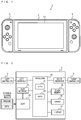
- FIG. 1 is a diagram showing a non-limiting example of the game system 1 of this embodiment.
- the game system 1 includes a body apparatus (non-limiting example image processing apparatus) 2 as a game apparatus, a left controller 3 , and a right controller 4 .
- the body apparatus 2 includes a display 12 .
- the left controller 3 and the right controller 4 may be removable from the body apparatus 2 .
- the left controller 3 is controlled using the user's left hand, and the right controller 4 is controlled using the user's right hand.
- the left controller 3 and the right controller 4 include a plurality of operation buttons, and an analog stick as a direction input unit.
- FIG. 2 is a block diagram showing a non-limiting example internal configuration of the game system 1 .
- the body apparatus 2 includes a processor 20 , a slot interface 23 , a slot 24 , a flash memory 25 , and a DRAM 26 .
- the processor 20 includes a central processing unit (CPU) 21 and a graphics processing unit (GPU) 22 .
- the CPU 21 can execute a game program to process operation data from the controllers 3 and 4 , execute a game process based on the operation data, and transmit an instruction to the GPU 22 to generate an image.
- the GPU 22 is a processor for performing image processing.
- the GPU 22 has a vertex shader function for converting coordinates of vertices of a virtual object. Note that the CPU 21 and the GPU 22 may be mounted on separate chips or may be mounted on a single chip as a system-on-a-chip (SoC).
- SoC system-on-a-chip
- the processor 20 is coupled to the slot interface 23 , the flash memory 25 , the DRAM 26 , and the display 12 .
- the processor 20 is also coupled through a left interface to the left controller 3 , and through a right interface to the right controller 4 .
- An external storage medium is removably inserted into the slot 24 .
- the external storage medium stores a program (a game program described below) and data (a flat ground object, etc., described below). Note that the program and data may be previously stored in the flash memory 25 , or may be downloaded and stored into the flash memory 25 through a network (e.g., the Internet).
- the program and data stored in the external storage medium are loaded to the DRAM 26 during the start of a game described below.
- the CPU 21 executes the program to perform a game process described below.
- the CPU 21 also transmits an instruction to the GPU 22 to display an image on the display 12 , and the GPU 22 renders an image according to the instruction, and causes the display 12 to display the image.
- the body apparatus 2 may be coupled to an external display apparatus different from the display 12 , and an image generated by the GPU 22 may be displayed on the external display apparatus.
- FIG. 3 is a diagram showing a non-limiting example virtual space in which the game of this embodiment is played.
- a virtual space is defined in the body apparatus 2 , and various virtual objects are disposed in the virtual space.
- a user moves a player character 40 in the virtual space using the left controller 3 and the right controller 4 , so that the game proceeds.
- an xyz orthogonal coordinate system is set in the virtual space.
- the x-axis is a lateral direction axis of the virtual space
- the z-axis is a depth direction axis of the virtual space
- the y-axis is a height direction axis of the virtual space.
- a ground object 30 and a river object 31 are disposed in the virtual space.
- the ground object 30 is a flat object, e.g. a surface parallel to the xz plane.
- the ground object 30 may be a substantially flat surface that has irregularities or unevenness (a generally flat surface), or may be an exactly flat surface that does not have irregularities or unevenness.
- the ground object 30 and the river object 33 are terrain objects representing the terrain in the virtual space.
- a house object 35 , a tree object 36 , and a cliff object 37 are disposed as virtual objects on the ground object 30 in the virtual space.
- the cliff object 37 is also a terrain object that represents a terrain in the virtual space.
- the player character 40 is disposed on a terrain object.
- a virtual camera VC is disposed behind the player character 40 .
- the user operates a controller (the left controller 3 or the right controller 4 ) to cause the player character 40 to move on the ground object 30 and perform a predetermined motion, so that the game proceeds.
- the virtual camera VC is located at a predetermined position behind the player character 40 , and is moved, depending on the movement of the player character 40 .
- the display 12 displays an image of the virtual space as viewed from the virtual camera VC.
- FIG. 4 is a diagram showing a non-limiting example image that is displayed on the display 12 when the game of this embodiment is being executed, where no grass objects are shown.
- FIG. 5 is a diagram showing a non-limiting example image that is displayed on the display 12 when the game of this embodiment is being executed, where grass objects 32 are displayed.
- an image containing the ground object 30 , the river object 31 , the house object 35 , the tree object 36 , and the player character 40 is displayed, on the display 12 , as a non-limiting example game image of the virtual space as viewed from the virtual camera VC.
- the flat ground object 30 is bent into a drum shape during image generation, and an image containing the ground object 30 , bent into a drum shape, is displayed on the display 12 .
- a boundary line between the ground object 30 and the background is displayed as a land horizon.
- the ground object 30 is divided into a plurality of objects such as a grassland object 30 a and a road object 30 b .
- the grassland object 30 a has a green color representing the presence of grass.
- the road object 30 b represents an earth region that is not covered with grass, and has a brown color.
- the user causes the player character 40 to move the player character 40 on the ground object 30 and perform a predetermined action.
- the user moves the player character 40 to the position of the tree object 36 , and causes the player character 40 to perform a predetermined motion (e.g., a motion of swaying the tree object 36 ).
- a predetermined motion e.g., a motion of swaying the tree object 36
- a fruit 36 a of the tree object 36 drops on the ground object 30
- the player character 40 acquires the fruit 36 a .
- the player character 40 is moved, or the player character 40 is caused to perform a predetermined action (e.g., a motion of picking up the fruit 36 a ) on an item object, so that the game proceeds.
- a predetermined action e.g., a motion of picking up the fruit 36 a
- grass objects 32 are displayed in the game of this embodiment as shown FIG. 5 .
- grass objects 32 are generated and displayed on and near the land horizon as viewed from the virtual camera VC.
- the grass object 32 is, for example, a triangular, green object.
- Two vertices included in the base of the grass object 32 are disposed so as to share the same positions as those of vertices of the ground object 30 , and the remaining vertex (peak vertex) of the grass object 32 is located at a higher position than that of the ground object 30 .
- Grass objects 32 are generated in a predetermined region (also hereinafter referred to as a “grass generation region”) located with reference to the land horizon.
- grass objects 32 are generated in a grass generation region including a region that includes the land horizon and is closer to the virtual camera VC than the land horizon is, and a region that is further from the virtual camera VC than the land horizon is in the line-of-sight direction of the virtual camera VC.
- Grass objects 32 are dynamically generated in a grass generation region located with reference to the land horizon.
- the virtual camera VC also moves, following the player character 40 .
- the position on the ground object 30 of the land horizon as viewed from the virtual camera VC differs before and after the movement of the player character 40 .
- the house object 35 is located substantially on the land horizon in the screen shown in FIG. 5 .
- the player character 40 moves in the depth direction of the screen (the positive line-of-sight direction of the virtual camera VC)
- the position of the land horizon on the display 12 remains unchanged, and the house object 35 is moved to a position located in front of the land horizon.
- the position on the ground object 30 of the land horizon moves further away from the house object 35 in the depth direction, depending on the movement of the player character 40 .
- the position on the ground object 30 of the land horizon also moves while the position on the display 12 of the land horizon remains unchanged. While the position of the land horizon moves, the grass generation region located with reference to the land horizon also moves.
- grass objects 32 are dynamically generated and displayed in the grass generation region located with reference to the land horizon.
- grass objects 32 are generated in a new grass generation region located with reference to the moved land horizon.
- Grass objects 32 that have been generated before the movement of the player character 40 are deleted if those grass objects 32 are no longer located in the grass generation region located with reference to the moved land horizon.
- the position on the ground object 30 of the land horizon moves, depending on the movement of the player character 40 , and grass objects 32 are newly generated in a grass generation region located with reference to the moved land horizon.
- grass objects 32 may be deleted by removing grass objects 32 disposed on the ground object 30 .
- a grass object 32 disposed on the ground object 30 may be deleted by removing the three vertices of the grass object 32 .
- a grass object 32 disposed on the ground object 30 may be deleted by setting the height of the grass object 32 to “0” so that the grass object 32 is not displayed.
- no grass objects 32 are generated in the predetermined region. Specifically, no grass objects 32 are generated in the region of the road object 30 b on the ground object 30 , in which the player character 40 is allowed to move.
- the road object 30 b is formed in a region around the house object 35 , and no grass objects 32 are generated in the region of the road object 30 b .
- no grass objects 32 are generated on the road object 30 b.
- No grass objects 32 are generated in regions of the grassland object 30 a , in which the player character 40 is allowed to move, other than the predetermined region located with reference to the land horizon. Specifically, no grass objects 32 are generated in a region of the grassland object 30 a that is located closer to the virtual camera VC than the predetermined region located with reference to the land horizon is.
- the virtual camera VC also moves, following the player character 40 . Therefore, during execution of the game, the player character 40 is located at a predetermined position (e.g., the center of the screen) on the display 12 . Because no grass objects 32 are generated in a region closer to the virtual camera VC than the predetermined region located with reference to the land horizon is, the player character 40 moves and performs a predetermined action in a region where no grass objects 32 are generated.
- the player character 40 is located in a region where grass objects 32 are generated, it may be difficult to see a necessary portion, an unnatural image may be displayed, or unnecessary calculation may be required.
- the feet of the player character 40 may be hidden by grass objects 32 and therefore it may be difficult to see the feet, or when the player character 40 performs a predetermined action on a predetermined item (e.g., to pick up an item dropped on the ground), it may be difficult to see the predetermined item.
- it may look as if the feet of the player character 40 were floating above the grass object 32 .
- a collision between the feet of the player character 40 and grass objects 32 may be calculated, and display may be controlled based on the result of the calculation. For example, when the feet of the player character 40 strike grass objects 32 , the grass objects 32 may be deformed.
- such a calculation is complicated, and if a large number of grass objects 32 are involved, a great burden is placed on the processor 20 .
- grass objects 32 are generated in a predetermined region located with reference to the land horizon, and are not generated in a region where the player character 40 is located. Therefore, such a problem can be avoided.
- grass objects 32 are generated in a grass generation region located with reference to the land horizon. Therefore, grass objects 32 having a predetermined height can be displayed in a land horizon portion, and the land horizon portion can be represented so as to look real.
- the grass image on the grassland object 30 a is not a three-dimensional virtual object, unlike the grass object 32 . Therefore, although a flat image is provided in a region closer to the virtual camera VC than the grass generation region is, the angle between the direction pointing from the virtual camera VC toward the closer region, and the ground object 30 , is so great that a natural image can be provided without the need of three-dimensional grass objects 32 .
- the land horizon portion the angle between the direction pointing from the virtual camera VC toward the land horizon, and the ground object 30 , is small. Therefore, if three-dimensional grass objects 32 are not generated, the land horizon portion is flat, and a less realistic image is likely to be generated. However, in this embodiment, grass objects 32 growing in the height direction are generated in the land horizon portion, and therefore, the land horizon portion can be represented so as to look natural.
- the flat ground object 30 and other objects ( 32 , 35 - 37 , 40 , etc.) on the ground object 30 are disposed.
- a portion of the virtual space including the ground object 30 and other objects, that is covered by at least the field of view of the virtual camera VC is deformed into a drum shape.
- a drum deformation process of deforming the virtual space into a drum shape will be described.
- the method for generating grass objects 32 will be described.
- FIG. 6 is a diagram showing a non-limiting example virtual space before the drum deformation process is performed.
- a ground object 30 is disposed as a terrain object, and a house object 35 is disposed on the ground object 30 .
- a virtual camera VC is set in the virtual space.
- a CxCyCz-coordinate system fixed to the virtual camera VC is set.
- the Cx-axis is a lateral direction axis of the virtual camera VC.
- the Cy-axis is an upward direction of the virtual camera VC.
- the Cz-axis is a line-of-sight direction of the virtual camera VC.
- the Cx-axis is set to be parallel to the x-axis of the virtual space.
- the virtual camera VC is also movable in the height direction of the virtual space. When the virtual camera VC is moved in the height direction, the virtual camera VC is turned around the Cx-axis (pitch direction). Because the Cx-axis is set to be parallel to the x-axis of the virtual space, the direction in which the line-of-sight direction of the virtual camera VC extends along the ground object 30 is parallel to the z-axis.
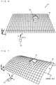
- FIG. 7 is a diagram showing a non-limiting example virtual space after the drum deformation process is performed.
- the entire terrain is deformed so that the ground object 30 extends along the side surface of a cylinder (drum).
- the entire train is deformed so that the ground object 30 that forms the terrain is at least a portion of the side surface of a cylinder having a radius of R and a central axis parallel to the x-axis of the virtual space.
- the Cx-axis of the virtual camera VC is set to be parallel to the x-axis of the virtual space
- the entire terrain is deformed so that the ground object 30 gradually becomes lower in the line-of-sight direction of the virtual camera VC (the depth direction of the screen when an image is displayed).
- a house object 35 (and other objects such as a tree object 36 and a player character 40 ) on the ground object 30 are deformed so that these objects are located along the ground object 30 .
- each of the vertices of the ground object 30 and each of the vertices of other objects disposed on the ground object 30 are subjected to coordinate conversion so that each vertex is turned around the x-axis.
- the drum deformation process will now be described in greater detail with reference to FIGS. 8 and 9 .
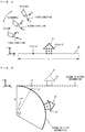
- FIG. 8 is a diagram showing a non-limiting example virtual space as viewed in a direction parallel to the x-axis before the drum deformation process is performed.
- FIG. 9 is a diagram showing a non-limiting example virtual space as viewed in a direction parallel to the x-axis after the drum deformation process is performed.
- the y-coordinate value and z-coordinate value of a vertex V 1 on the ground object 30 are (y1, z1). It is also assumed that the y-coordinate value and z-coordinate value of a vertex V 2 of the house object 35 are (y2, z2). It is also assumed that a predetermined distance in the z-axis direction is L. Note that L is a fixed value.
- the height of the virtual camera VC is changed according to the user's operation. For example, it is assumed that the position of the virtual camera VC can be set to “low,” “normal,” and “high.” When the virtual camera VC is located at the “low” position, the line-of-sight direction of the virtual camera VC is set to a first direction, and the angle between the z-axis and the Cz-axis is set to a relatively small value (e.g., 0-20 degrees). In this case, an image of the virtual space as viewed from a side is displayed on the display 12 .
- a relatively small value e.g., 0-20 degrees
- the line-of-sight direction of the virtual camera VC is set to a second direction pointing further downward than the first direction, and the angle between the z-axis and the Cz-axis is set to a value (e.g., 45 degrees) greater than when the virtual camera VC is located at the “low” position.
- a value e.g. 45 degrees
- the line-of-sight direction of the virtual camera VC is set to a third direction pointing further downward than the second direction, and the angle between the z-axis and the Cz-axis is set to a relatively great value (e.g., 60-70 degrees).
- a relatively great value e.g. 60-70 degrees
- the vertices V 1 and V 2 of FIG. 8 are displaced to vertices V 1 ′ and V 2 ′ shown in FIG. 9 .
- the y-coordinate value and z-coordinate value (y′, z′) of a vertex V′ after displacement are calculated based on the y-coordinate value and z-coordinate value (y, z) of a vertex V before displacement, using expressions 1-5. Note that the x-coordinate value of each vertex remains unchanged.
- ⁇ represents the central angle of an arc that is determined based on the height of the virtual camera VC.
- All the vertices of the ground object 30 and the objects on the ground object 30 are subjected to the coordinate conversion based on expressions 1-5. Specifically, each vertex is subjected to the coordinate conversion based on expressions 1-5, which depends on the position of the vertex in the z-axis direction. In other words, each vertex is subjected to the coordinate conversion based on expressions 1-5, which depends on the position of the vertex in the depth direction along the ground object 30 .
- the vertex V 1 on the ground object 30 is displaced to a position on the arc having a radius of R and a central angle of ⁇ .
- the ground object 30 is deformed so as to form a portion of the side surface of a cylinder having a radius of R.
- the vertex V 2 of the house object 35 on the ground object 30 is subjected to similar coordinate conversion to be displaced to a position shown in FIG. 9 .
- the house object 35 is disposed on the side surface of the cylinder.
- each vertex is displaced by the GPU 22 using the vertex shader function.
- the GPU 22 performs the coordinate conversion based on expressions 1-5 according to an instruction from the CPU 21 .
- the GPU 22 performs a rendering process based on the virtual camera VC, and causes the display 12 to display an image.
- the vertices of the ground object 30 and the objects on the ground object 30 are displaced by the GPU 22 using the vertex shader function, so that the entire terrain is deformed.
- ⁇ is determined by the line-of-sight direction of the virtual camera VC (the height of the virtual camera VC). For example, when the line-of-sight direction of the virtual camera VC is set to the first direction, ⁇ is set to a first value. When the line-of-sight direction of the virtual camera VC is set to the second direction, ⁇ is set to a second value greater than the first value. Specifically, when the line-of-sight direction of the virtual camera VC is set to the second direction pointing further downward than the first direction, ⁇ is set to a greater value. In other words, when the line-of-sight direction of the virtual camera VC is the second direction pointing further downward than the first direction, the resultant deformed ground has a greater curvature.
- the value of ⁇ is set to a third value smaller than the first and second values.
- the resultant deformed ground has a smaller curvature.
- the drum deformation process may not be performed.
- the process of deforming the terrain and objects on the terrain into a drum shape may not be performed.
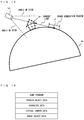
- FIG. 10 is a diagram for describing a method for determining a grass generation region.
- FIG. 11 is a diagram showing a non-limiting example height of the grass object 32 .
- the CPU 21 calculates the tangent line from the position of the virtual camera VC to the ground object 30 after the drum deformation process.
- the point of tangency between the tangent line and the drum-shaped ground object 30 is indicated by P.
- a line determined based on the point P of tangency is a land horizon (a boundary line between the ground object 30 and the background) as viewed from the virtual camera VC.
- a tangent line (perpendicular to the x-axis) may be drawn from the position of the virtual camera VC to the ground object 30
- a land horizon may be defined as a straight line that passes through the point P of tangency of the tangent line, extending in parallel to the x-axis.
- the CPU 21 determines, as a grass generation region, a predetermined region including a region that includes the point P of tangency (land horizon) and is closer to the virtual camera VC than the land horizon is, and a region that is further from the virtual camera VC than the point P of tangency is in the line-of-sight direction of the virtual camera VC (in a direction away from the virtual camera VC).
- the grass generation region is determined before the drum deformation process is actually performed.
- the CPU 21 calculates the tangent line that will be in contact with a cylindrical object when the drum deformation process has been performed on the flat ground object 30 .
- the land horizon may not be included in the field of view of the virtual camera VC. In this case, a tangent line cannot be drawn, and therefore, a grass generation region is not present, and no grass objects 32 are generated. For example, when the virtual camera VC is located at the “high” position of FIG. 8 , the land horizon is not be included in the field of view of the virtual camera VC, and therefore, no grass objects 32 are generated.
- the CPU 21 determines a grass generation region
- the CPU 21 disposes a plurality of grass objects 32 in the grass generation region on the flat ground object 30 , and determines the height of each grass object 32 .
- the height of the grass object 32 varies depending on the distance from the virtual camera VC.
- the height of the grass object 32 is determined so as to decrease with a decrease in the distance from the virtual camera VC.
- the height of the grass object 32 gradually becomes higher in the depth direction (the line-of-sight direction of the virtual camera VC) in a range from a position closer to the virtual camera VC than the point P of tangency is to the point P of tangency.
- the height of the grass object 32 is greatest at the point P of tangency (land horizon), and in a region B extending from the point P of tangency in the depth direction, the greatest height is maintained.
- grass objects 32 are disposed on the ground object 30 , but the heights of the grass objects 32 are set to “0.”
- the three vertices of each grass object 32 are disposed on the ground object 30 . Therefore, in the region C, it looks like there is no growth of the grass objects 32 .
- no grass objects 32 are disposed (i.e., the three vertices are not disposed).
- the peak vertex of a triangular grass object 32 is displaced by the GPU 22 using the vertex shader function, so that the grass object 32 is generated and displayed. Specifically, the height of the grass object 32 determined by the CPU 21 is input to the GPU 22 , which in turn displaces the position of the peak vertex of the grass object 32 by coordinate conversion. As a result, the peak vertices of grass objects 32 are moved in the vertical direction, and therefore, it looks like grass objects 32 seamlessly appear.
- the drum deformation process is performed by the GPU 22 displacing the vertices of each object using the vertex shader function. Thereafter, the GPU 22 generates an image of the virtual space, which is displayed on the display 12 as shown in FIG. 5 .
- FIG. 12 is a diagram showing a non-limiting example in which the virtual camera VC has moved relative to the ground object 30 from the state of FIG. 10 .
- the position of the point P of tangency on the ground object 30 moves. While in FIG. 10 the grass generation region is located closer to the virtual camera VC than the house object 35 is, in FIG. 12 the grass generation region is located beyond the house object 35 .
- the grass generation region moves, depending on the movement of the virtual camera VC in the depth direction.
- the tangent line from the virtual camera VC to the cylindrical ground object 30 is calculated and the grass generation region is set in real time.
- grass objects 32 are generated or removed, depending on the movement of the virtual camera VC in the depth direction.
- the height of the grass object 32 is changed, depending on the movement of the virtual camera VC in the depth direction.
- the player character 40 and the virtual camera VC may be moved on the ground object 30 by moving the player character 40 and the virtual camera VC in the virtual space in the depth direction.
- the player character 40 and the virtual camera VC may be apparently moved in the depth direction by turning the entire drum-shaped terrain with the positions of the player character 40 and the virtual camera VC remaining unchanged.
- the player character 40 and the virtual camera VC may be moved in the virtual space, or the drum-shaped terrain may be turned with the positions in the virtual space of the player character 40 and the virtual camera VC fixed.
- the drum-shaped terrain may be turned by adding an angle corresponding to the amount of movement in the depth direction when the coordinate conversion described with reference to FIG. 9 is performed.
- OFFSET is determined based on the movement in the depth direction of the player character 40 .
- expression 1′ “rad” is calculated based on a value obtained by adding the OFFSET value to z. Thereafter, “rad” calculated using expression 1′ is substituted into expressions 2 and 5, so that the coordinate values of a converted vertex V are calculated.
- the entire terrain can be deformed into a drum shape, and the entirety of the drum-shaped terrain can be turned around the central axis of the drum, and therefore, apparent movement of the virtual camera VC can be achieved without actually moving the virtual camera VC in the virtual space.
- by adding the OFFSET value to the z-coordinate value as in expression 1′ it looks as if the virtual camera VC moved in the depth direction by the amount of “OFFSET.”
- grass objects 32 are generated in a predetermined region that is located on the ground object 30 with reference to a boundary line (land horizon) between the ground object 30 and the background as viewed from the virtual camera VC. Therefore, the boundary line portion on the ground object 30 can be represented so as to look real.
- the player character 40 is located closer to the virtual camera VC than the predetermined region is, and moves and performs a predetermined action in a region where no grass objects 32 are generated. As a result, it can be reliably easy to see scenes that the player character 40 moves and performs a predetermined action on a predetermined item.
- Grass objects 32 are generated so as to gradually become longer toward the boundary line from a region closer to the virtual camera VC than the boundary line is. Because longer grass objects 32 are formed on the boundary line of the ground object 30 , the scene that grass objects 32 grow upward from the ground object 30 in the virtual space can be enhanced, resulting in an increase in reality.
- the ground object 30 is deformed along the circumferential direction of a cylinder as viewed from the virtual camera VC, and therefore, it can be easier to see the scene that grass objects 32 grow from the land horizon portion.
- the heights of grass objects 32 are adjusted by the GPU 22 using the vertex shader function in real time. As a result, it is not necessary to previously prepare grass objects 32 having different heights.
- a grass object 32 can be moved by displacing a vertex of the grass object 32 using the vertex shader function of the GPU 22 .
- the scene that grass objects 32 sway can be displayed by displacing the peak vertices of the grass objects 32 rightward and leftward.
- the amount of data may be large, and the grass objects 32 may sway monotonously.
- vertices of grass objects 32 are displaced by the GPU 22 using the vertex shader function, it is not necessary to prepare such a moving image.
- the swaying of grass objects 32 can be represented so as to look natural.
- the vertices of a flat terrain and objects on the terrain are displaced in real time by the GPU 22 using the vertex shader function.
- the vertex shader function As a result, it is not necessary to previously prepare a curved terrain.
- other objects the house object 35 and the tree object 36 disposed on the terrain need to be created so as to fit the curved surface, and therefore, a game creator needs to spend a lot of time and effort.
- the curvature of the drum is decreased ( ⁇ is decreased) when the line-of-sight direction of the virtual camera VC is the first direction, and the curvature of the drum is increased ( ⁇ is increased) when the line-of-sight direction of the virtual camera VC is the second direction pointing further downward than the first direction.
- the curvature is small, and therefore, even when the entire terrain is deformed into a drum shape, an image that is natural to the user can be provided. For example, if the curvature is extremely great, the entire terrain looks greatly curved, so that an image that is unnatural to the user is likely to be displayed.
- the curvature of the drum is set to a small value, and therefore, such an unnatural feeling is less likely to occur.
- FIG. 13 is a diagram showing non-limiting example data stored in the body apparatus 2 (the DRAM 26 thereof).
- the body apparatus 2 stores a game program, terrain object data, character data, virtual camera data, and grass object data.
- the body apparatus 2 stores various kinds of data such as operation data corresponding to the user's operation, and other data of items, etc., used in a game.
- the game program is for executing a game of this embodiment.
- the game program is, for example, stored in an external storage medium, and loaded from the external storage medium to the DRAM 26 during the start of the game.
- the terrain object data is related to an object representing a terrain in the virtual space.
- the terrain object data contains the flat ground object 30 , the flat river object 31 , on which no grass objects 32 are generated, etc.
- the terrain object data also contains data that is related to the grassland object 30 a , on which grass objects 32 can be generated, and the road object 30 b , on which no grass objects 32 are generated.
- Data related to the ground object 30 contains a plurality of vertices.
- the object data indicates other kinds of objects (the house object 35 , the tree object 36 , the cliff object 37 , etc.) disposed on a terrain.
- Each piece of object data contains a plurality of vertices.
- a piece of object data contains, as data indicating each vertex, data indicating a position relative to a representative vertex.
- an object e.g., the house object 35
- the coordinate values in the virtual space of each vertex of the object are determined based on data indicating the relative position thereof.
- the object data is, for example, stored in an external storage medium, and loaded from the external storage medium to the DRAM 26 during the start of the game.
- the character data contains data indicating the player character 40 disposed on a terrain.
- the data indicating the player character 40 contains a plurality of vertices, and as data indicating each vertex, data indicating a position relative to a representative vertex.
- the character data may contain data indicating a character that is controlled by the CPU 21 (so-called CPU character).
- the virtual camera data which is related to a state of the virtual camera VC, indicates the position in the virtual space, line-of-sight direction, etc., of the virtual camera VC.
- the grass object data is related to each grass object 32 .
- the data related to each grass object 32 contains data indicating the position of the grass object 32 and data indicating the height of the grass object 32 .
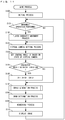
- FIG. 14 is a flowchart showing a non-limiting example game process performed in the processor 20 of the body apparatus 2 .
- the process of FIG. 14 is performed by the CPU 21 or the GPU 22 of the body apparatus 2 executing a game program. Note that FIG. 14 shows only processes related to the generation of grass objects 32 and the drum deformation process, and does not show the other processes (e.g., the process of causing the player character 40 to perform a predetermined action, etc.).
- the CPU 21 performs an initial process (step S 100 ).
- a fixed xyz-coordinate system is set in the virtual space, and each object is disposed in the virtual space.
- a terrain including a flat ground object, a river object, etc. is formed in the virtual space, and other objects (the house object 35 , the tree object 36 , the player character 40 , etc.) are disposed on the terrain.
- the positions in the virtual space of the vertices of each object are determined.
- the virtual camera VC is disposed in the virtual space.
- step S 101 the CPU 21 executes step S 101 . Thereafter, the CPU 21 executes steps S 101 -S 110 repeatedly, i.e. at predetermined frame time intervals (e.g., 1/60 sec).
- predetermined frame time intervals e.g., 1/60 sec.
- step S 101 the CPU 21 obtains operation data from a controller (the left controller 3 or the right controller 4 ), and based on the operation data, determines whether or not an operation of moving the player character 40 has been performed (step S 101 ).
- step S 101 If it is determined that an operation of moving the player character 40 has been performed (step S 101 : YES), the CPU 21 performs a process of moving the player character 40 (step S 102 ). For example, when the user inputs an instruction to move in the depth direction (z-axis direction), the CPU 21 moves the player character 40 in the depth direction.
- step S 102 If step S 102 has been executed or if the determination result of step S 101 is negative (NO), the CPU 21 performs a virtual camera setting process (step S 103 ). Specifically, the CPU 21 sets the height (line-of-sight direction) of the virtual camera VC according to the user's operation. When the user changes the height of the virtual camera VC, the CPU 21 sets the height (position and line-of-sight direction) of the virtual camera VC.
- the CPU 21 sets the central angle ⁇ , depending on the state of the virtual camera VC (step S 104 ). Specifically, the CPU 21 sets the central angle ⁇ based on the line-of-sight direction (height) of the virtual camera VC set in step S 103 .
- the CPU 21 determines whether or not the player character 40 has moved in the depth direction (z-axis direction) according to the user's operation (step S 105 ).
- the CPU 21 sets an offset value (step S 106 ).
- the offset value set in this case is the “OFFSET” of expression 1′.
- the CPU 21 sets the offset value based on the movement of the player character 40 in the z-axis direction. For example, the CPU 21 sets a negative offset value if the player character 40 has moved in the positive z-axis direction, and a positive offset value if the player character 40 has moved in the negative z-axis direction.
- step S 106 If step S 106 has been executed or if the determination result of step S 105 is negative (NO), the CPU 21 performs a grass generation process (step S 107 ).
- the grass generation process of step S 107 will now be described in detail.
- FIG. 15 is a flowchart showing a non-limiting example of the grass generation process of step S 107 .
- the CPU 21 calculates the tangent line from the position of the virtual camera VC to the ground object 30 deformed in a drum shape, in the field of view of the virtual camera VC (step S 120 ).
- the CPU 21 determines a grass generation region (step S 121 ). Specifically, the CPU 21 determines, as a grass generation region, a predetermined region on the ground object 30 that includes the point P of tangency (a region including a region closer to the virtual camera VC than the point P of tangency is and a region further or deeper from the virtual camera VC than the point P of tangency is).
- the CPU 21 disposes a plurality of grass objects 32 in the determined grass generation region (step S 122 ).
- the CPU 21 may dispose a plurality of grass objects 32 in the grass generation region so that the grass objects 32 are equally spaced.
- a plurality of grass objects 32 are disposed in the grass generation region of the flat ground object 30 .
- the CPU 21 does not dispose a grass object 32 in a region of the grass generation region determined in step S 121 that no grass objects are not allowed to be generated (e.g., the region of the road object 30 b ).
- step S 122 the CPU 21 determines the height of each grass object 32 (step S 123 ).
- the method for determining the height of the grass object 32 is as described above with reference to FIG. 11 .
- the CPU 21 generates grass objects 32 in the grass generation region (step S 124 ). Specifically, the CPU 21 transmits an instruction to the GPU 22 to displace the peak vertex of each grass object 32 , depending on the determined height of the grass object 32 .
- the GPU 22 performs coordinate conversion on the peak vertices of the grass objects 32 using the vertex shader function according to the instruction, to displace the peak vertex of each grass object 32 . As a result, the grass objects 32 are generated on the ground object 30 in the grass generation region.
- step S 124 After execution of step S 124 , the CPU 21 returns to the process of FIG. 14 .
- the CPU 21 causes the GPU 22 to execute the drum deformation process of deforming the terrain and each object on the terrain (step S 108 ).
- the GPU 22 displaces the vertices of the terrain object 30 and each object (the grass objects 32 , the house object 35 , the tree object 36 , the player character 40 , etc.) on the terrain object 30 , using the vertex shader function.
- the flat ground is deformed to form a portion of the side surface of a cylinder, and the objects on the ground are also deformed to fit the side surface of the cylinder. Note that if the offset value has been set in step S 106 , the displacement of the vertices is calculated using expression 1′.
- the CPU 21 causes the GPU 22 to perform a rendering process based on the virtual camera VC (step S 109 ).
- a rendering process based on the virtual camera VC
- the generated image is output to the display 12 , on which the image of the virtual space is displayed (step S 110 ).
- step S 108 are performed only on vertices included in the field of view (image capture range) of the virtual camera VC. In other words, the drum deformation process is not performed on vertices that are not included in the field of view of the virtual camera VC.
- step S 110 If step S 110 has been performed, the CPU 21 executes step S 101 again. Thus, FIG. 14 has been described.
- step S 107 and the drum deformation process of step S 108 are executed repeatedly, i.e. at frame time intervals. Even when the player character 40 moves in the z-axis direction, so that the position on the ground object 30 of the land horizon is changed, the grass generation process is performed in real time.
- the tangent line from the virtual camera VC to the ground object 30 deformed in a drum shape is calculated, and based on the point P of tangency, a grass generation region is determined. Thereafter, a plurality of grass objects 32 are disposed in the grass generation region, the heights of the grass objects 32 are determined, and the vertices of the grass object 32 are displaced, whereby the grass objects 32 are generated.
- the grass objects 32 are generated in a predetermined region that is located with reference to a boundary line between the ground object 30 and the background as viewed from the virtual camera VC.
- the ground surface can be represented so as to look real.
- grass objects 32 are generated on the grassland object 30 a
- grass objects are not the only objects that are generated.
- a snow object having a height may be generated in a predetermined region located with reference to the boundary line between the ground object 30 and the background.
- a snow object may be formed of a single triangular polygon like a grass object, or may be a combination of a plurality of triangles.
- a height of a snow object (a height of accumulated snow) may be greatest at the boundary line like the grass object 32 , and may gradually become smaller toward the virtual camera VC in a region closer to the virtual camera VC than the boundary line is.
- any suitable predetermined object having a height may be generated in the predetermined region.
- grass objects 32 are generated in the predetermined region located with reference to the land horizon.
- the predetermined region located with reference to the land horizon may be either a region that includes the land horizon or a region that does not include the land horizon (e.g., a region closer to the virtual camera VC than the land horizon is).
- objects are generated in a predetermined region located with reference to the land horizon that is a boundary line between the ground object 30 and the background as viewed from the virtual camera VC.
- a predetermined object having a height is generated in a predetermined region located with reference to a boundary line between any suitable terrain object and the background as viewed from the virtual camera VC.
- a predetermined object may be generated in a predetermined region located with reference to a sea horizon that is a boundary line between a terrain object representing a sea, lake, or river and the background.
- a scene that the sea horizontal portion undulates may be represented by generating wave object having a predetermined height as the predetermined object in a predetermined region located with reference to the sea horizon.
- a mountain or heel object having a height may be disposed in the virtual space, and a predetermined object may be generated in a predetermined region located with reference to a boundary line between the mountain or heel object and the background (a boundary line as viewed from the virtual camera VC).
- a terrain object representing any terrain may be disposed in the virtual space, and a predetermined object may be disposed in a predetermined region located with reference to a boundary line (also referred to as a “ridge line”) between the terrain object and the background.
- a boundary line also referred to as a “ridge line”
- the boundary line refers to a boundary between a terrain object and the background as viewed from the virtual camera VC, such as a land horizon, a sea horizon, and a contour of a mountain when the mountain is viewed in front of the background.
- the ground object 30 is assumed to have a drum shape (the side surface of a cylinder).
- the terrain object may have a spherical shape or any other suitable curved shape.
- the drum deformation process of deforming the ground object 30 into a drum shape is performed, the drum deformation process may not necessarily be performed. Specifically, when a flat terrain is displayed, a predetermined object may be generated in a predetermined region located with reference to a boundary line between the flat terrain and the background.
- coordinate conversion is performed on each vertex by the GPU 22 using the vertex shader function. In another embodiment, coordinate conversion may be performed on each vertex by the CPU 21 .
- the above game is merely for illustrative purposes.
- the above-described process may be performed in any other suitable games.
- the above process is performed in the body apparatus 2 of the game system 1 .
- the above process may be performed in any other suitable image processing apparatuses (e.g., a personal computer, smartphone, and tablet terminal), etc.
- the above process may be performed in an image processing system including a plurality of apparatuses (e.g., a system including a terminal and a server).
Landscapes
- Engineering & Computer Science (AREA)
- Theoretical Computer Science (AREA)
- Physics & Mathematics (AREA)
- Multimedia (AREA)
- Computer Graphics (AREA)
- General Physics & Mathematics (AREA)
- Software Systems (AREA)
- Geometry (AREA)
- Computing Systems (AREA)
- Computer Hardware Design (AREA)
- General Engineering & Computer Science (AREA)
- Human Computer Interaction (AREA)
- Radar, Positioning & Navigation (AREA)
- Remote Sensing (AREA)
- Architecture (AREA)
- Processing Or Creating Images (AREA)
Abstract
Description
rad=θ×(z/L) (1)
temp_y=y+R (2)
y_t=temp_y×cos(rad) (3)
y′=y_t−R (4)
z′=temp_y×sin(rad) (5)
rad=θ×((z+OFFSET)/L) (1′)
Claims (29)
Applications Claiming Priority (3)
| Application Number | Priority Date | Filing Date | Title |
|---|---|---|---|
| JPJP2019-054189 | 2019-03-22 | ||
| JP2019054189A JP7223610B2 (en) | 2019-03-22 | 2019-03-22 | Image processing program, image processing system, image processing apparatus, and image processing method |
| JP2019-054189 | 2019-03-22 |
Publications (2)
| Publication Number | Publication Date |
|---|---|
| US20200298117A1 US20200298117A1 (en) | 2020-09-24 |
| US11219829B2 true US11219829B2 (en) | 2022-01-11 |
Family
ID=72513857
Family Applications (1)
| Application Number | Title | Priority Date | Filing Date |
|---|---|---|---|
| US16/682,049 Active US11219829B2 (en) | 2019-03-22 | 2019-11-13 | Non-transitory computer-readable storage medium storing image processing program, image processing system, image processing apparatus, and image processing method |
Country Status (2)
| Country | Link |
|---|---|
| US (1) | US11219829B2 (en) |
| JP (1) | JP7223610B2 (en) |
Families Citing this family (9)
| Publication number | Priority date | Publication date | Assignee | Title |
|---|---|---|---|---|
| US9332285B1 (en) * | 2014-05-28 | 2016-05-03 | Lucasfilm Entertainment Company Ltd. | Switching modes of a media content item |
| CN111667563B (en) * | 2020-06-19 | 2023-04-07 | 抖音视界有限公司 | Image processing method, device, equipment and storage medium |
| US11481962B2 (en) | 2020-06-26 | 2022-10-25 | Gree, Inc. | Information processing device, information processing method, and information processing program |
| JP7270675B2 (en) * | 2021-05-27 | 2023-05-10 | グリー株式会社 | Information processing system, information processing method, information processing program |
| US11995859B2 (en) | 2021-10-28 | 2024-05-28 | Mineral Earth Sciences Llc | Sparse depth estimation from plant traits |
| US12231616B2 (en) * | 2021-10-28 | 2025-02-18 | Deere & Company | Sparse and/or dense depth estimation from stereoscopic imaging |
| JP7849798B2 (en) * | 2023-06-29 | 2026-04-22 | グリーホールディングス株式会社 | Information processing device, information processing method, and program |
| JP7614279B2 (en) * | 2023-09-14 | 2025-01-15 | 任天堂株式会社 | GAME PROGRAM, GAME SYSTEM, GAME PROCESSING METHOD, AND GAME DEVICE |
| JP7614280B2 (en) * | 2023-09-14 | 2025-01-15 | 任天堂株式会社 | GAME PROGRAM, GAME SYSTEM, GAME DEVICE, AND GAME PROCESSING METHOD |
Citations (10)
| Publication number | Priority date | Publication date | Assignee | Title |
|---|---|---|---|---|
| US20060258444A1 (en) * | 2005-05-13 | 2006-11-16 | Nintendo Co., Ltd. | Storage medium having game program stored thereon and game apparatus |
| JP2006318389A (en) | 2005-05-16 | 2006-11-24 | Namco Bandai Games Inc | Program, information storage medium, and image generation system |
| JP2009129167A (en) | 2007-11-22 | 2009-06-11 | Namco Bandai Games Inc | Program, information storage medium, and image generation system |
| US8031193B1 (en) * | 2007-01-25 | 2011-10-04 | Rockwell Collins, Inc. | Dynamic light shading in terrain rendering applications |
| US20130210524A1 (en) * | 2012-02-15 | 2013-08-15 | Nintendo Co., Ltd. | Image processing system, game system, image processing method, image processing apparatus and recording medium |
| US20160307369A1 (en) * | 2013-12-13 | 2016-10-20 | Aveva Solutions Limited | Image rendering of laser scan data |
| US20170294047A1 (en) * | 2016-04-08 | 2017-10-12 | Nintendo Co., Ltd. | Image processing apparatus and storage medium |
| US20180365905A1 (en) * | 2015-08-11 | 2018-12-20 | Amazon Technologies, Inc. | Virtual area generation and manipulation |
| US20190034056A1 (en) * | 2017-07-26 | 2019-01-31 | Adobe Systems Incorporated | Manipulating a camera perspective within a three-dimensional space |
| US20190070505A1 (en) * | 2017-09-01 | 2019-03-07 | Square Enix Ltd | Method and system for rendering video game images |
Family Cites Families (4)
| Publication number | Priority date | Publication date | Assignee | Title |
|---|---|---|---|---|
| JP4056021B2 (en) * | 1997-12-05 | 2008-03-05 | 株式会社バンダイナムコゲームス | Image generating apparatus and information storage medium |
| JP4610748B2 (en) * | 2001-01-16 | 2011-01-12 | 株式会社バンダイナムコゲームス | Image generation system, program, and information storage medium |
| JP4688405B2 (en) * | 2003-02-07 | 2011-05-25 | 株式会社バンダイナムコゲームス | PROGRAM, INFORMATION STORAGE MEDIUM, AND GAME DEVICE |
| JP4804120B2 (en) * | 2005-11-17 | 2011-11-02 | 株式会社バンダイナムコゲームス | Program, information storage medium, and image generation system |
-
2019
- 2019-03-22 JP JP2019054189A patent/JP7223610B2/en active Active
- 2019-11-13 US US16/682,049 patent/US11219829B2/en active Active
Patent Citations (13)
| Publication number | Priority date | Publication date | Assignee | Title |
|---|---|---|---|---|
| US20060258444A1 (en) * | 2005-05-13 | 2006-11-16 | Nintendo Co., Ltd. | Storage medium having game program stored thereon and game apparatus |
| JP2006314633A (en) | 2005-05-13 | 2006-11-24 | Nintendo Co Ltd | GAME PROGRAM AND GAME DEVICE |
| JP2006318389A (en) | 2005-05-16 | 2006-11-24 | Namco Bandai Games Inc | Program, information storage medium, and image generation system |
| US8031193B1 (en) * | 2007-01-25 | 2011-10-04 | Rockwell Collins, Inc. | Dynamic light shading in terrain rendering applications |
| JP2009129167A (en) | 2007-11-22 | 2009-06-11 | Namco Bandai Games Inc | Program, information storage medium, and image generation system |
| JP2013168022A (en) | 2012-02-15 | 2013-08-29 | Nintendo Co Ltd | Image processing system, game system, image processing method, image processing device and computer program |
| US20130210524A1 (en) * | 2012-02-15 | 2013-08-15 | Nintendo Co., Ltd. | Image processing system, game system, image processing method, image processing apparatus and recording medium |
| US20160307369A1 (en) * | 2013-12-13 | 2016-10-20 | Aveva Solutions Limited | Image rendering of laser scan data |
| US20180365905A1 (en) * | 2015-08-11 | 2018-12-20 | Amazon Technologies, Inc. | Virtual area generation and manipulation |
| US20170294047A1 (en) * | 2016-04-08 | 2017-10-12 | Nintendo Co., Ltd. | Image processing apparatus and storage medium |
| JP2017188002A (en) | 2016-04-08 | 2017-10-12 | 任天堂株式会社 | Image processing apparatus, image processing system, and image processing method |
| US20190034056A1 (en) * | 2017-07-26 | 2019-01-31 | Adobe Systems Incorporated | Manipulating a camera perspective within a three-dimensional space |
| US20190070505A1 (en) * | 2017-09-01 | 2019-03-07 | Square Enix Ltd | Method and system for rendering video game images |
Non-Patent Citations (3)
| Title |
|---|
| English translation of Office Action issued in Japanese Applicaiton No. 2019-054189 dated Nov. 8, 2021(5 pages). |
| Stappers (NPL "Experiencing non-Newtonian physics in Virtual Reality") Citation: Stappers, "Experiencing non-Newtonian physics in Virtual Reality", Delft University of Technology, 1997 (Year: 1997). * |
| Youtube Video titled "[Ludum Dare #30] This Little Piggy: Behind the Scenes", URL https://www.youtube.com/watch?v=H7-3dZTERf0, 2014. (Year: 2014). * |
Also Published As
| Publication number | Publication date |
|---|---|
| US20200298117A1 (en) | 2020-09-24 |
| JP7223610B2 (en) | 2023-02-16 |
| JP2020154923A (en) | 2020-09-24 |
Similar Documents
| Publication | Publication Date | Title |
|---|---|---|
| US11219829B2 (en) | Non-transitory computer-readable storage medium storing image processing program, image processing system, image processing apparatus, and image processing method | |
| US8882593B2 (en) | Game processing system, game processing method, game processing apparatus, and computer-readable storage medium having game processing program stored therein | |
| JP2020080007A (en) | Information processor, information processing program, information processing system, and information processing method | |
| CN111773719B (en) | Virtual object rendering method and device, storage medium, and electronic device | |
| US20090244064A1 (en) | Program, information storage medium, and image generation system | |
| US8662976B2 (en) | Game processing system, game processing method, game processing apparatus, and computer-readable storage medium having game processing program stored therein | |
| JP6576874B2 (en) | Image processing apparatus, image processing system, and image processing method | |
| US11244499B2 (en) | Information processing apparatus, non-transitory computer-readable storage medium storing information processing program, information processing system, and information processing method | |
| CA2968589C (en) | System and method for placing a character animation at a location in a game environment | |
| US9147288B1 (en) | Subdivision of surfaces approximation | |
| JP4407434B2 (en) | Image processing apparatus, image processing method, and image processing program | |
| JP6503098B1 (en) | Image processing apparatus, image processing program and image processing method | |
| CN111467800B (en) | Fusion method and device of virtual three-dimensional model | |
| JP2003022452A (en) | Image processor and solid-shape display program | |
| US20100177098A1 (en) | Image generation system, image generation method, and computer program product | |
| JP2020080008A (en) | Information processing apparatus, information processing program, information processing system, and information processing method | |
| KR20220041712A (en) | Lidar-based real-time point image processing and display method and apparatus therefor | |
| US20240282034A1 (en) | Apparatus, systems and methods for animation data | |
| JP6454671B2 (en) | Image processing apparatus, image processing method, program, and recording medium | |
| CN117635814B (en) | Drivable 3D digital human body modeling method, system and equipment based on RGBD data | |
| JP2003228725A (en) | 3D image processing system | |
| KR102534464B1 (en) | System for generating virtual golf course having the geometry of real golf courses, and method for providing putting pracice using the system | |
| EP1788500B1 (en) | Storage medium having game program stored therin, and game apparatus and game processing method therefor | |
| CN115364480A (en) | Game scene construction method and device | |
| US20250242262A1 (en) | Storage medium, game system, game apparatus, and game processing method |
Legal Events
| Date | Code | Title | Description |
|---|---|---|---|
| AS | Assignment |
Owner name: NINTENDO CO., LTD., JAPAN Free format text: ASSIGNMENT OF ASSIGNORS INTEREST;ASSIGNORS:YONEZU, MAKOTO;TAKAHASHI, KOJI;TAKAMURA, JUN;REEL/FRAME:050991/0924 Effective date: 20191023 |
|
| FEPP | Fee payment procedure |
Free format text: ENTITY STATUS SET TO UNDISCOUNTED (ORIGINAL EVENT CODE: BIG.); ENTITY STATUS OF PATENT OWNER: LARGE ENTITY |
|
| STPP | Information on status: patent application and granting procedure in general |
Free format text: FINAL REJECTION MAILED |
|
| STPP | Information on status: patent application and granting procedure in general |
Free format text: DOCKETED NEW CASE - READY FOR EXAMINATION |
|
| STPP | Information on status: patent application and granting procedure in general |
Free format text: NON FINAL ACTION MAILED |
|
| STPP | Information on status: patent application and granting procedure in general |
Free format text: RESPONSE TO NON-FINAL OFFICE ACTION ENTERED AND FORWARDED TO EXAMINER |
|
| STPP | Information on status: patent application and granting procedure in general |
Free format text: NOTICE OF ALLOWANCE MAILED -- APPLICATION RECEIVED IN OFFICE OF PUBLICATIONS |
|
| STPP | Information on status: patent application and granting procedure in general |
Free format text: PUBLICATIONS -- ISSUE FEE PAYMENT VERIFIED |
|
| STCF | Information on status: patent grant |
Free format text: PATENTED CASE |
|
| STPP | Information on status: patent application and granting procedure in general |
Free format text: AWAITING TC RESP., ISSUE FEE NOT PAID |
|
| STPP | Information on status: patent application and granting procedure in general |
Free format text: PUBLICATIONS -- ISSUE FEE PAYMENT VERIFIED |
|
| STCF | Information on status: patent grant |
Free format text: PATENTED CASE |
|
| MAFP | Maintenance fee payment |
Free format text: PAYMENT OF MAINTENANCE FEE, 4TH YEAR, LARGE ENTITY (ORIGINAL EVENT CODE: M1551); ENTITY STATUS OF PATENT OWNER: LARGE ENTITY Year of fee payment: 4 |