US11218810B2 - Electric motor - Google Patents
Electric motor Download PDFInfo
- Publication number
- US11218810B2 US11218810B2 US16/374,866 US201916374866A US11218810B2 US 11218810 B2 US11218810 B2 US 11218810B2 US 201916374866 A US201916374866 A US 201916374866A US 11218810 B2 US11218810 B2 US 11218810B2
- Authority
- US
- United States
- Prior art keywords
- driving element
- magnetic
- magnet
- magnetic pole
- magnet assembly
- Prior art date
- Legal status (The legal status is an assumption and is not a legal conclusion. Google has not performed a legal analysis and makes no representation as to the accuracy of the status listed.)
- Active
Links
Images


Classifications
-
- H—ELECTRICITY
- H04—ELECTRIC COMMUNICATION TECHNIQUE
- H04R—LOUDSPEAKERS, MICROPHONES, GRAMOPHONE PICK-UPS OR LIKE ACOUSTIC ELECTROMECHANICAL TRANSDUCERS; DEAF-AID SETS; PUBLIC ADDRESS SYSTEMS
- H04R9/00—Transducers of moving-coil, moving-strip, or moving-wire type
- H04R9/02—Details
- H04R9/025—Magnetic circuit
-
- H—ELECTRICITY
- H04—ELECTRIC COMMUNICATION TECHNIQUE
- H04R—LOUDSPEAKERS, MICROPHONES, GRAMOPHONE PICK-UPS OR LIKE ACOUSTIC ELECTROMECHANICAL TRANSDUCERS; DEAF-AID SETS; PUBLIC ADDRESS SYSTEMS
- H04R1/00—Details of transducers, loudspeakers or microphones
- H04R1/02—Casings; Cabinets ; Supports therefor; Mountings therein
- H04R1/021—Casings; Cabinets ; Supports therefor; Mountings therein incorporating only one transducer
-
- H—ELECTRICITY
- H04—ELECTRIC COMMUNICATION TECHNIQUE
- H04R—LOUDSPEAKERS, MICROPHONES, GRAMOPHONE PICK-UPS OR LIKE ACOUSTIC ELECTROMECHANICAL TRANSDUCERS; DEAF-AID SETS; PUBLIC ADDRESS SYSTEMS
- H04R2209/00—Details of transducers of the moving-coil, moving-strip, or moving-wire type covered by H04R9/00 but not provided for in any of its subgroups
- H04R2209/021—Reduction of eddy currents in the magnetic circuit of electrodynamic loudspeaker transducer
-
- H—ELECTRICITY
- H04—ELECTRIC COMMUNICATION TECHNIQUE
- H04R—LOUDSPEAKERS, MICROPHONES, GRAMOPHONE PICK-UPS OR LIKE ACOUSTIC ELECTROMECHANICAL TRANSDUCERS; DEAF-AID SETS; PUBLIC ADDRESS SYSTEMS
- H04R2209/00—Details of transducers of the moving-coil, moving-strip, or moving-wire type covered by H04R9/00 but not provided for in any of its subgroups
- H04R2209/022—Aspects regarding the stray flux internal or external to the magnetic circuit, e.g. shielding, shape of magnetic circuit, flux compensation coils
-
- H—ELECTRICITY
- H04—ELECTRIC COMMUNICATION TECHNIQUE
- H04R—LOUDSPEAKERS, MICROPHONES, GRAMOPHONE PICK-UPS OR LIKE ACOUSTIC ELECTROMECHANICAL TRANSDUCERS; DEAF-AID SETS; PUBLIC ADDRESS SYSTEMS
- H04R9/00—Transducers of moving-coil, moving-strip, or moving-wire type
- H04R9/02—Details
- H04R9/04—Construction, mounting, or centering of coil
Definitions
- the present invention relates to transducers and more specifically to transducers that use a magnet assembly, such as an electric motor, which can be in the form of a linear electrical motor.
- a speaker is a type of electro-acoustic transducer, which is a device that converts an electrical audio signal into sound corresponding to the signal. Speakers were invented during the development of telephone systems in the late 1800s. However, it was electronic amplification, initially by way of vacuum tube technology beginning around 1912 that began to make speaker systems practical. The amplified speaker systems were used in radios, phonographs, public address systems and theatre sound systems for talking motion pictures starting in the 1920s.
- Thea dynamic speaker which is widely used today, was invented in 1925 by Edward Kellogg and Chester Rice.
- a principle of the dynamic speaker is when an electrical audio signal input is applied through a voice coil, which is a coil of wire suspended in a circular gap between the poles of a permanent magnet, the coil is forced to move rapidly back and forth due to Faraday's law of induction. The movement causes a diaphragm, which is generally conically shaped, and is attached to the coil to move back and forth, thereby inducing movement of the air to create sound waves.
- Speakers are typically housed in an enclosure and if high quality sound is required, multiple speakers may be mounted in the same enclosure, with each reproducing part of the audio frequency range. In this arrangement the speakers are individually referred to as “drivers” and the entire enclosure is referred to as a speaker or a loudspeaker. Small speakers are found in various devices such as radio and TV receivers, and a host of other devices including phones and computer systems.
- speaker efficiency which is defined as the sound power output divided by the electrical power input, is only about 1%. So very little of the electrical energy sent by an amplifier to a typical speaker is converted to acoustic energy. The remainder of the energy is converted to heat, mostly in the voice coil and magnet assembly. The main reason for this is the difficulty of achieving a proper impedance matching between the acoustic impedance of the drive unit and the air it radiates into.
- the efficiency of speaker drivers varies with frequency as well as the magnetic intensity available to interact with the voice coil.
- Linear motors are an electric motor that produces a linear force along a length of the motor.
- the most common version has magnets of alternating polarities aligned along a plane with electrical coils changing polarity proximate to the magnets.
- the present invention provides a transducer in the form of a linear electric motor that uses a magnetic assembly having an intense magnetic field.
- the present invention in one form is an electric motor including a driven element, a magnet assembly and a driving element.
- the driven element being driven in a direction of movement.
- the magnet assembly is includes first and second magnets each having first and second magnetic poles.
- the first magnetic pole of the first magnet and the first magnetic pole of the second magnet being proximate to each other and facing each other thereby defining a first magnetic zone therebetween.
- the first magnetic poles all being similar, and the second magnetic poles all being similar.
- the driving element is proximate to the magnet assembly, producing a magnetic field within the driving element that is primarily orthogonal to the direction of movement.
- the present invention in another form is directed to a load driving machine having an electric motor including a driven element, a magnet assembly and a driving element.
- the driven element being driven in a direction of movement.
- the magnet assembly is includes first and second magnets each having first and second magnetic poles.
- the first magnetic pole of the first magnet and the first magnetic pole of the second magnet being proximate to each other and facing each other thereby defining a first magnetic zone therebetween.
- the first magnetic poles all being similar, and the second magnetic poles all being similar.
- the driving element is proximate to the magnet assembly, producing a magnetic field within the driving element that is primarily orthogonal to the direction of movement.
- the present invention advantageously produces an intense magnetic field.
- Another advantage of the present invention is that it allows the electric motor to efficiently utilize the electrical power provided thereto.
- FIG. 1 is a perspective view of a speaker system that utilizes an embodiment of a transducer of the present invention
- FIG. 2 is a cut away view of the speaker system of FIG. 1 ;
- FIG. 3 is a cut away view of a speaker of the speaker system of FIGS. 1 and 2 ;
- FIG. 4 is a perspective cut away view of another embodiment of a speaker using the transducer of the present invention.
- FIG. 5 is a planar cut away view of the speaker of FIG. 4 further illustrating the transducer of the present invention
- FIG. 6 is a perspective cut away view of the magnetic assembly of the speakers of FIGS. 1-5 ;
- FIG. 7 is a planar cut away view of the magnetic assembly of FIG. 6 ;
- FIG. 8 is a schematical view of the magnetic assembly of FIGS. 6 and 7 illustrating a flow of magnetic flux in the magnetic circuit
- FIG. 9 is a schematical view of another embodiment of a magnetic assembly for use with the speakers of FIGS. 1-5 illustrating a flow of magnetic flux in the magnetic circuit;
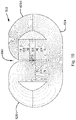
- FIG. 10 is a schematical view of yet another embodiment of a magnetic assembly for use with the speakers of FIGS. 1-5 illustrating a flow of magnetic flux in the magnetic circuit;
- FIG. 11 is a schematical view of still yet another embodiment of a magnetic assembly for use with the speakers of FIGS. 1-5 illustrating a flow of magnetic flux in the magnetic circuit;
- FIG. 12 is a perspective cut away view of an embodiment of a planar transducer in the form of a planar speaker having a magnetic assembly of the present invention
- FIG. 13 is a planar cut away view of the speaker of FIG. 12 ;
- FIG. 14 is another schematical view of a magnetic assembly for use as a transducer of the present invention illustrating the magnetic flux of the magnetic circuit;
- FIG. 15 illustrates a closer view of flux lines associated with the air gap of magnetic assembly of the present invention
- FIG. 16 illustrates a closer view of flux lines associated with the air gap of magnetic assembly of FIG. 11 ;
- FIG. 17 illustrates a geometry of another embodiment of the present invention.
- FIG. 18 illustrates the configuration of the prior art and the accompanying asymmetric flux lines in the air gap
- FIG. 19 illustrates a geometry of another embodiment of the present invention.
- FIG. 20 illustrates a geometry of yet another embodiment of the present invention
- FIG. 21 illustrates a geometry of still yet another embodiment of the present invention.
- FIG. 22 is a perspective view of another embodiment of a transducer in the form of an electric motor
- FIG. 23 is a perspective view of the electric motor of FIG. 22 with the casing and top coil removed to show the configuration of the magnets;
- FIG. 24 is a top view of the electric motor of FIGS. 22 and 23 with the top coil removed to show the magnet assembly;
- FIG. 25 is a perspective view of the coils and magnet assembly of the motor of FIGS. 22-24 ;
- FIG. 26 is a view of flux lines of the electric motor of FIGS. 22-25 with an application of electrical current to the coils with the magnet assembly being currently centered;
- FIG. 27 is a view of the flux lines of the electric motor of FIGS. 22-25 with an application of electrical current to the coils with the magnet assembly being moved due to the application of the magnetic field of the coils;
- FIG. 28 is a cutaway side view of the electric motor of FIGS. 22-27 providing another view of the present invention.
- a speaker system 10 including an enclosure 12 and a transducer 14 in the form of an acoustic speaker 14 .
- Speaker 14 incudes a load 16 - 20 that is a speaker diaphragm 16 or cone 16 , a collar 18 and a voice coil 20 .
- Diaphragm 16 is suspended around its periphery and is moved by collar 18 to produce movements of air to thereby produce sound.
- Voice coil 20 is a winding of wire coupled to the collar 18 that is positioned in a magnetic field of a magnet assembly 22 .
- FIG. 3 there is shown a cut away view of speaker 14 showing more details of magnet assembly 22 which includes ferrous members 24 , 26 A, 26 B magnets 28 , 30 , 36 and 38 , and ferrous members 32 and 34 .
- Ferrous members 24 , 26 A and 26 B together have a combined shape that is similar to a nearly closed C-shape, with collar 18 passing therethrough.
- Ferrous members 24 , 26 A and 26 B are arranged and shaped in order to largely contain and direct flux from magnets 28 , 30 , 36 and 38 , all of which have a circular form.
- Ferrous members 32 and 34 can also be thought of as being magnetic zones 32 and 34 that are formed due to the orientation of the magnets in contact with the respective ferrous members 32 and 34 .
- FIGS. 4 and 5 there is illustrated another embodiment of a speaker 114 . Similar items in the various embodiments have a multiple of 100 associated with its reference number and the descriptions of one corresponds generally to the description of the other, with any differences being specifically discussed.
- FIGS. 6 and 7 there are shown some additional details of magnet assembly 22 .
- An air gap 40 is illustrated existing between ferrous members 32 and 34 , which is where the intensity of the magnetic field is directed and has its most intense focus.
- the magnetic field strength in this region may be 2 Tesla, or 3 Tesla, or even 4 Tesla, with even higher levels possible. Such a high magnetic field strength will cause the current passing through voice coil 20 to have a much greater effect, to thereby increase the efficiency of transducer 14 .
- the magnetic pole orientation if illustrated on the right side of FIGS. 6 and 7 showing how the poles are arranged in a bucking fashion and will be held in place by the assembly of ferrous members 24 , 26 A and 26 B with fasteners, not illustrated.
- the ring magnets 28 , 30 , 36 and 38 may individually have approximately the same field strength, or ring magnets 28 and 30 may have a higher magnetic field density to compensate for their smaller diameter relative to magnets 36 and 38 .
- FIG. 8 there is shown a magnet assembly 122 , which can be understood to be similar to magnet assembly 22 and illustrates the magnetic circuit thereof.
- the lines of flux are shown and it can be seen that the highest intensity, illustrated by the closeness of the flux lines, occurs in air gap 140 , particularly where ferrous members 132 and 134 are aligned with each other.
- the field lines are generally and even substantially symmetrical in air gap 140 .
- the construct of ferrous members 124 , 126 A and 126 B are optimized to substantially contain and direct the magnetic flux lines to thereby largely shield the surrounding environment from being influenced by the magnetic filed arranged in magnet assembly 122 .
- the magnetic field lines in ferrous members 132 and 134 can be considered magnetic zones with the area or zone therebetween in air gap 140 having a very intense free air magnetic intensity.
- FIGS. 9-11 there are illustrated different embodiments of the present invention illustrating variations of possible magnetic circuits that are contemplated that result in the desired high magnetic field strength in air gap 140 , 440 .
- the magnetic field symmetry in air gap 140 is nearly absolute and will vary only by the minor variations in the materials used and dimensional considerations.
- the magnetic field symmetry in air gap 440 is still substantially symmetric in a vertical direction and is substantially symmetrical in a horizontal direction, directly laterally to the right of ferrous member 432 .
- the magnetic field symmetry is still generally symmetrical in directions departing from the lateral outward direction from ferrous member 432 .
- FIGS. 12 and 13 there are illustrated another embodiment of the present invention of a transducer 514 in the form of a planar speaker 514 .
- Magnets 528 , 530 , 536 and 538 are here substantially linear and yet the construct is such that the operation is similar to the previously discussed embodiments.
- the coil 520 is again positioned in the high intensity magnetic field afforded by the construct geometry.
- FIG. 14 there is illustrated yet another embodiment of the present invention, which illustrates the use of larger and more powerful magnets 630 and 638 relative to magnets 628 and 636 .
- ferrous members 632 and 634 have beveled ends that lead to air gap 40 with voice coil 20 being positioned at the focal high intensity magnetic field zone, again having substantial symmetry in the vertical and horizontal directions. As can be seen substantially all of the magnetic field of the magnetic circuit is contained within the construct of magnet assembly 622 .
- FIG. 15 there is shown a closer view of air gap 140 .
- the symmetry of the flux lines even in this magnified view, show remarkable symmetry in air gap 140 .
- Magnet pairs 128 and 130 as well as 136 and 138 are in a bucking configuration with similar poles facing each other. This arrangement dramatically increases the intensity of the magnetic field in air gap 140 between ferrous members 132 and 134 .
- FIG. 16 In contrast to the symmetry of the flux lines in FIG. 15 , please now refer to FIG. 16 , where the flux lines of the construct of FIG. 11 are shown in a closer view, where there is now less symmetry in the horizontal direction when vertically displaced from ferrous member 432 .
- FIG. 17 there is shown another geometry of the present invention for the production of an intense magnetic field in air gap 740 .
- This rendition also has significant symmetry in the flux lines in air gap 740 .
- FIG. 18 is a single magnet prior art configuration of a magnetic assembly 50 having a magnet 52 , and ferrous pieces 54 and 56 positioned to form an air gap 58 that illustrates the asymmetrical magnetic flux lines of the prior art construct of a magnetic assembly 50 .
- FIG. 19 there is shown another embodiment of the present invention having three magnets 830 , 836 and 838 . Again, this is a cross-sectional view of one part of a ring magnetic assembly 822 .
- the magnetic field emanating from the S pole of magnet 830 is magnetically proximate to the magnetic zone present in ferrous member 834 .
- FIG. 20 there is shown still yet another embodiment of the present invention having differing sizes of magnets 928 , 930 , 936 and 938 , each also having differing magnetic strengths. Additionally, ferrous members 932 and 934 are shaped in an upward fashion to show the associated pathway of magnetic flux lines and the creation of an intense magnetic field in air gap 940 .
- FIG. 21 there is shown a magnetic assembly 1022 (again in cross-section as a part of a ring magnetic assembly 1022 having magnets 1028 , 1030 , 1036 , 1038 , 1042 and 1044 , and ferrous members 1032 , 1034 , 1046 and 1048 positioned between pairs of the magnets.
- the magnets are ring magnets with one set radially outward from the inner set.
- the magnetic pole orientations are in a bucking orientation so that the surrounding ferrous members 24 , 26 A and 26 B not only provide a path for the magnetic lines to congregate, but also provide physical strength to hold magnetic assemblies 22 together.
- the magnets generally are ring magnets having a common axis and several are positioned radially apart while the magnets that are axially spaced are in a magnetic bucking orientation. Also, pairs of radially separated magnets are concentrically located.
- the geometry of the magnetic assembly may have the radially apart magnets have their poles aligned in a bucking configuration and that magnetic zones be formed therebetween with an air gap being provided in either a radially inward manner or a radially outward manner.
- a transducer 1114 is in the form of a load driving machine 1114 that is configured to drive a load 1116 in a direction of motion D, with machine 1114 taking the form of a linear electric motor 1114 .
- Load 1116 may be in the form of a speaker diaphragm 1116 , or some other load that is to be driven in a linear manner.
- a driven element 1170 has a magnet assembly 1176 with a frame that holds magnets 1128 , 1130 , and 1142 , having ferrous elements 1132 and 1146 placed between the three magnets. Note the orientation of magnets 1128 , 1130 , and 1142 is such that similar polarities are oriented to face each other, which as in the previous examples is used to intensify the field density. Driven element 1170 slides on shafts that have springs 1172 thereon, which serve to bias the position of driven element 1170 in a central location, until driving elements 1178 A and 1178 B are energized with an electric current.
- Driving elements 1178 A and 1178 B have a void with a width 1180 with a magnetic field within the void being generally orientated in an orthogonal direction OD relative to the direction of movement D.
- Driving elements 1178 A and 1178 B are electrical coils 1178 A and 1178 B, which are substantially similar and are coupled to an electrical driving circuit, which along with known electrical connections, is not shown for the sake of clarity.
- driving elements 1178 A and 1178 B are driven with a signal, such as an electrical signal from an audio amplifier, magnetic fields are created and changed to thereby cause a movement of shafts 1174 that are coupled to driven element 1170 in a direction D.
- Magnets 1128 , 1130 , and 1142 may have a width that is less than a length of the void in coils 1178 A and 1178 B. A length 1182 of magnets 1128 , 1130 , and 1142 may be proximate to the width 1180 of the void.
- the void may be filled with non-ferrous material, such as a potting compound. It is also contemplated to have a ferrous component within the void, but it is preferably not used, thereby reducing the magnetic reluctance of the magnetic circuit.
- FIGS. 26 and 27 the flux lines associated with driven element 1170 and driving elements 1178 A and 1178 B are shown with FIG. 26 illustrating the application of a magnetic field when driven element 1170 was centered in the gap 1140 .
- the magnets 1128 , 1130 , and 1142 , and ferrous elements 1132 and 1146 are identified in their positional sequence associated with reference number 1170 in FIGS. 26 and 27 (due to the difficulty in coupling these reference numbers to their associated elements amidst the flux lines). Due to the application of the magnetic field as shown in FIG. 26 , driven element 1170 is driven to the right as shown in FIG. 27 with ferrous element 1132 generally centered in the void.
- the magnetic field created between magnets 1130 and 1142 serve to self-limit the extent to which driven element 1170 is driven to the right, in this illustration.
- the magnetic fields generated by coils 1178 A and 1178 B are such that the same magnetic polarity that is generated thereby are each directed at magnet assembly 1176 . This is in contrast to prior art assemblies in which dual coils project opposite magnetic polarities on each side of a magnet arrangement.
- the present invention balances the magnetic fields so that movement of driven element 1170 occurs with minimal or no side force occurs that may lead to a binding of driven element 1170 on the shafts that help define its motion.
Abstract
Description
Claims (20)
Priority Applications (1)
| Application Number | Priority Date | Filing Date | Title |
|---|---|---|---|
| US16/374,866 US11218810B2 (en) | 2015-08-04 | 2019-04-04 | Electric motor |
Applications Claiming Priority (4)
| Application Number | Priority Date | Filing Date | Title |
|---|---|---|---|
| US14/817,513 US9668060B2 (en) | 2015-08-04 | 2015-08-04 | Transducer |
| US15/151,908 US9807510B2 (en) | 2015-08-04 | 2016-05-11 | Transducer |
| US15/797,404 US10375479B2 (en) | 2015-08-04 | 2017-10-30 | Electric motor |
| US16/374,866 US11218810B2 (en) | 2015-08-04 | 2019-04-04 | Electric motor |
Related Parent Applications (1)
| Application Number | Title | Priority Date | Filing Date |
|---|---|---|---|
| US15/797,404 Division US10375479B2 (en) | 2015-08-04 | 2017-10-30 | Electric motor |
Publications (2)
| Publication Number | Publication Date |
|---|---|
| US20190230443A1 US20190230443A1 (en) | 2019-07-25 |
| US11218810B2 true US11218810B2 (en) | 2022-01-04 |
Family
ID=61281494
Family Applications (2)
| Application Number | Title | Priority Date | Filing Date |
|---|---|---|---|
| US15/797,404 Active US10375479B2 (en) | 2015-08-04 | 2017-10-30 | Electric motor |
| US16/374,866 Active US11218810B2 (en) | 2015-08-04 | 2019-04-04 | Electric motor |
Family Applications Before (1)
| Application Number | Title | Priority Date | Filing Date |
|---|---|---|---|
| US15/797,404 Active US10375479B2 (en) | 2015-08-04 | 2017-10-30 | Electric motor |
Country Status (1)
| Country | Link |
|---|---|
| US (2) | US10375479B2 (en) |
Families Citing this family (11)
| Publication number | Priority date | Publication date | Assignee | Title |
|---|---|---|---|---|
| US11528562B2 (en) | 2011-12-23 | 2022-12-13 | Shenzhen Shokz Co., Ltd. | Bone conduction speaker and compound vibration device thereof |
| US11601761B2 (en) | 2011-12-23 | 2023-03-07 | Shenzhen Shokz Co., Ltd. | Bone conduction speaker and compound vibration device thereof |
| US11706574B2 (en) | 2014-01-06 | 2023-07-18 | Shenzhen Shokz Co., Ltd. | Systems and methods for suppressing sound leakage |
| US11582564B2 (en) | 2014-01-06 | 2023-02-14 | Shenzhen Shokz Co., Ltd. | Systems and methods for suppressing sound leakage |
| US11570556B2 (en) | 2014-01-06 | 2023-01-31 | Shenzhen Shokz Co., Ltd. | Systems and methods for suppressing sound leakage |
| US11617045B2 (en) | 2014-01-06 | 2023-03-28 | Shenzhen Shokz Co., Ltd. | Systems and methods for suppressing sound leakage |
| US11582563B2 (en) | 2014-01-06 | 2023-02-14 | Shenzhen Shokz Co., Ltd. | Systems and methods for suppressing sound leakage |
| US11172308B2 (en) * | 2015-08-04 | 2021-11-09 | Curtis E. Graber | Electric motor |
| DK180111B1 (en) | 2018-10-04 | 2020-05-06 | Upper Level Aps | A magnet system for an electromechanical transducer |
| EP3952336A4 (en) * | 2019-04-30 | 2022-05-18 | Shenzhen Shokz Co., Ltd. | Acoustic output apparatus |
| GB2593749B (en) * | 2020-04-01 | 2024-01-03 | B & W Group Ltd | Improvements in and relating to loudspeaker magnet assemblies |
Citations (34)
| Publication number | Priority date | Publication date | Assignee | Title |
|---|---|---|---|---|
| US3877314A (en) | 1973-03-26 | 1975-04-15 | Illinois Tool Works | Accelerometer |
| US4785816A (en) * | 1985-01-14 | 1988-11-22 | Johnson & Johnson Ultrasound Inc. | Ultrasonic transducer probe assembly |
| US5142260A (en) | 1991-03-08 | 1992-08-25 | Harman International Industries, Incorporated | Transducer motor assembly |
| US5446797A (en) | 1992-07-17 | 1995-08-29 | Linaeum Corporation | Audio transducer with etched voice coil |
| DE19725373A1 (en) | 1997-06-19 | 1998-12-24 | Andreas Nuske | Permanent magnet electrodynamic drive |
| US5898544A (en) | 1997-06-13 | 1999-04-27 | Hutchinson Technology Incorporated | Base plate-mounted microactuator for a suspension |
| US5901235A (en) * | 1997-09-24 | 1999-05-04 | Eminent Technology, Inc. | Enhanced efficiency planar transducers |
| US20010031060A1 (en) | 2000-01-07 | 2001-10-18 | Carver Robert W. | Compact speaker system |
| US20020131612A1 (en) | 2001-03-16 | 2002-09-19 | Samsung Electro-Mechanics Co., Ltd. | Dual magnetic structure of vibration speaker |
| US6542617B1 (en) | 1999-05-26 | 2003-04-01 | Sony Corporation | Speaker |
| US6563932B2 (en) | 2001-01-16 | 2003-05-13 | Kh Technology | Magnet system for loudspeakers |
| US6600399B1 (en) * | 2002-02-05 | 2003-07-29 | Roland Pierre Trandafir | Transducer motor/generator assembly |
| US20040086150A1 (en) | 2002-11-05 | 2004-05-06 | Stiles Enrique M. | Push-push multiple magnetic air gap transducer |
| US20040156527A1 (en) * | 2003-02-07 | 2004-08-12 | Stiles Enrique M. | Push-pull electromagnetic transducer with increased Xmax |
| US20050175213A1 (en) | 2002-11-05 | 2005-08-11 | Stiles Enrique M. | Electromagnetic transducer having a low reluctance return path |
| US20050190945A1 (en) | 2004-02-26 | 2005-09-01 | Calderwood Richard C. | Shorting ring fixture for electromagnetic transducer |
| US20060204028A1 (en) | 2005-03-11 | 2006-09-14 | Samsung Electronics Co., Ltd. | Speaker apparatus |
| US20070075906A1 (en) | 2000-03-25 | 2007-04-05 | Forster Ian J | Multiple feed point slot antenna |
| US20070104346A1 (en) * | 2005-10-27 | 2007-05-10 | Pioneer Corporation | Speaker |
| US20080219469A1 (en) * | 2006-09-15 | 2008-09-11 | Hpv Technologies Llc | Full Range Planar Magnetic Microphone And Arrays Thereof |
| US20110062916A1 (en) | 2009-09-17 | 2011-03-17 | Qualcomm Incorporated | Movable magnetically resonant antenna for wireless charging |
| US20110305355A1 (en) * | 2009-02-27 | 2011-12-15 | Tohoku Pioneer Corporation | Vibration direction converter part for speaker device and speaker device |
| US20110311088A1 (en) * | 2010-06-17 | 2011-12-22 | Sony Corporation | Acoustic conversion device and acoustic conversion device assembly method |
| US20120051188A1 (en) | 2010-08-26 | 2012-03-01 | Graber Curtis E | Submersible electro-dynamic acoustic projector |
| US20120051557A1 (en) * | 2009-02-26 | 2012-03-01 | Tohoku Pioneer Corporation | Voice coil for speaker device, and speaker device |
| US20120257646A1 (en) | 2011-04-05 | 2012-10-11 | Microsoft Corporation | Thermal management system |
| US20130142364A1 (en) | 2011-12-02 | 2013-06-06 | Thomas Paul Heed | Linear Interleaved Magnetic Motor and Loudspeaker Transducer Using Same |
| US20130285479A1 (en) * | 2010-11-30 | 2013-10-31 | Seiko Instruments Inc. | Electromagnetic generator |
| WO2014137009A1 (en) | 2013-03-07 | 2014-09-12 | 주식회사 엑셀웨이 | High-output plate-type speaker comprising stacked magnetic circuit |
| US20140270326A1 (en) * | 2013-03-15 | 2014-09-18 | James J. Croft, III | Planar-Magnetic Transducer With Improved Electro-Magnetic Circuit |
| US8861776B2 (en) | 2010-03-25 | 2014-10-14 | Claudio Lastrucci | Electromechanical conversion system with moving magnets; acoustic diffuser comprising said system and a moving member that generates sound waves |
| US8891809B2 (en) | 2010-08-25 | 2014-11-18 | Harman International Industries, Inc. | Split magnet loudspeaker |
| US9161141B2 (en) | 2013-02-22 | 2015-10-13 | Siemens Aktiengesellschaft | Wireless charging system for hearing instruments |
| US9312924B2 (en) | 2009-02-10 | 2016-04-12 | Qualcomm Incorporated | Systems and methods relating to multi-dimensional wireless charging |
-
2017
- 2017-10-30 US US15/797,404 patent/US10375479B2/en active Active
-
2019
- 2019-04-04 US US16/374,866 patent/US11218810B2/en active Active
Patent Citations (38)
| Publication number | Priority date | Publication date | Assignee | Title |
|---|---|---|---|---|
| US3877314A (en) | 1973-03-26 | 1975-04-15 | Illinois Tool Works | Accelerometer |
| US4785816A (en) * | 1985-01-14 | 1988-11-22 | Johnson & Johnson Ultrasound Inc. | Ultrasonic transducer probe assembly |
| US5142260A (en) | 1991-03-08 | 1992-08-25 | Harman International Industries, Incorporated | Transducer motor assembly |
| US5446797A (en) | 1992-07-17 | 1995-08-29 | Linaeum Corporation | Audio transducer with etched voice coil |
| US5898544A (en) | 1997-06-13 | 1999-04-27 | Hutchinson Technology Incorporated | Base plate-mounted microactuator for a suspension |
| DE19725373A1 (en) | 1997-06-19 | 1998-12-24 | Andreas Nuske | Permanent magnet electrodynamic drive |
| US5901235A (en) * | 1997-09-24 | 1999-05-04 | Eminent Technology, Inc. | Enhanced efficiency planar transducers |
| US6542617B1 (en) | 1999-05-26 | 2003-04-01 | Sony Corporation | Speaker |
| US20010031060A1 (en) | 2000-01-07 | 2001-10-18 | Carver Robert W. | Compact speaker system |
| US20070075906A1 (en) | 2000-03-25 | 2007-04-05 | Forster Ian J | Multiple feed point slot antenna |
| US6563932B2 (en) | 2001-01-16 | 2003-05-13 | Kh Technology | Magnet system for loudspeakers |
| US20020131612A1 (en) | 2001-03-16 | 2002-09-19 | Samsung Electro-Mechanics Co., Ltd. | Dual magnetic structure of vibration speaker |
| US6600399B1 (en) * | 2002-02-05 | 2003-07-29 | Roland Pierre Trandafir | Transducer motor/generator assembly |
| US20060182303A1 (en) | 2002-02-05 | 2006-08-17 | Trandafir Roland P | Microphone assembly |
| US20040086150A1 (en) | 2002-11-05 | 2004-05-06 | Stiles Enrique M. | Push-push multiple magnetic air gap transducer |
| US20050031154A1 (en) | 2002-11-05 | 2005-02-10 | Stiles Enrique M. | Electromagnetic transducer having multiple magnetic air gaps whose magnetic flux is in a same direction |
| US20050175213A1 (en) | 2002-11-05 | 2005-08-11 | Stiles Enrique M. | Electromagnetic transducer having a low reluctance return path |
| US6940992B2 (en) | 2002-11-05 | 2005-09-06 | Step Technologies Inc. | Push-push multiple magnetic air gap transducer |
| US7006654B2 (en) | 2003-02-07 | 2006-02-28 | Step Technologies, Inc. | Push-pull electromagnetic transducer with increased Xmax |
| US20040156527A1 (en) * | 2003-02-07 | 2004-08-12 | Stiles Enrique M. | Push-pull electromagnetic transducer with increased Xmax |
| US20050190945A1 (en) | 2004-02-26 | 2005-09-01 | Calderwood Richard C. | Shorting ring fixture for electromagnetic transducer |
| US20060204028A1 (en) | 2005-03-11 | 2006-09-14 | Samsung Electronics Co., Ltd. | Speaker apparatus |
| US20070104346A1 (en) * | 2005-10-27 | 2007-05-10 | Pioneer Corporation | Speaker |
| US20080219469A1 (en) * | 2006-09-15 | 2008-09-11 | Hpv Technologies Llc | Full Range Planar Magnetic Microphone And Arrays Thereof |
| US9312924B2 (en) | 2009-02-10 | 2016-04-12 | Qualcomm Incorporated | Systems and methods relating to multi-dimensional wireless charging |
| US20120051557A1 (en) * | 2009-02-26 | 2012-03-01 | Tohoku Pioneer Corporation | Voice coil for speaker device, and speaker device |
| US20110305355A1 (en) * | 2009-02-27 | 2011-12-15 | Tohoku Pioneer Corporation | Vibration direction converter part for speaker device and speaker device |
| US20110062916A1 (en) | 2009-09-17 | 2011-03-17 | Qualcomm Incorporated | Movable magnetically resonant antenna for wireless charging |
| US8861776B2 (en) | 2010-03-25 | 2014-10-14 | Claudio Lastrucci | Electromechanical conversion system with moving magnets; acoustic diffuser comprising said system and a moving member that generates sound waves |
| US20110311088A1 (en) * | 2010-06-17 | 2011-12-22 | Sony Corporation | Acoustic conversion device and acoustic conversion device assembly method |
| US8891809B2 (en) | 2010-08-25 | 2014-11-18 | Harman International Industries, Inc. | Split magnet loudspeaker |
| US20120051188A1 (en) | 2010-08-26 | 2012-03-01 | Graber Curtis E | Submersible electro-dynamic acoustic projector |
| US20130285479A1 (en) * | 2010-11-30 | 2013-10-31 | Seiko Instruments Inc. | Electromagnetic generator |
| US20120257646A1 (en) | 2011-04-05 | 2012-10-11 | Microsoft Corporation | Thermal management system |
| US20130142364A1 (en) | 2011-12-02 | 2013-06-06 | Thomas Paul Heed | Linear Interleaved Magnetic Motor and Loudspeaker Transducer Using Same |
| US9161141B2 (en) | 2013-02-22 | 2015-10-13 | Siemens Aktiengesellschaft | Wireless charging system for hearing instruments |
| WO2014137009A1 (en) | 2013-03-07 | 2014-09-12 | 주식회사 엑셀웨이 | High-output plate-type speaker comprising stacked magnetic circuit |
| US20140270326A1 (en) * | 2013-03-15 | 2014-09-18 | James J. Croft, III | Planar-Magnetic Transducer With Improved Electro-Magnetic Circuit |
Non-Patent Citations (1)
| Title |
|---|
| Notification of Transmittal of the International Search Report and the Written Opinion of the International Searching Authority, or the Declaration dated Oct. 20, 2016 for International Application No. PCT/US2016/041319 (11 pages). |
Also Published As
| Publication number | Publication date |
|---|---|
| US10375479B2 (en) | 2019-08-06 |
| US20190230443A1 (en) | 2019-07-25 |
| US20180070182A1 (en) | 2018-03-08 |
Similar Documents
| Publication | Publication Date | Title |
|---|---|---|
| US11218810B2 (en) | Electric motor | |
| US7706563B2 (en) | Concentric radial ring motor | |
| US10743097B1 (en) | Bidirectional speaker using bar magnets | |
| US20060093180A1 (en) | Magnetic circuit having dual magnets, speaker and vibration generating apparatus using the same | |
| US8135162B2 (en) | Multiple magnet loudspeaker | |
| CA2838456C (en) | An electromechanical-electroacoustic transducer with low thickness and high travel range and relevant manufacturing method | |
| EP2871856B1 (en) | Dual coil moving magnet transducer | |
| US20070297639A1 (en) | Multiple magnet loudspeaker | |
| KR101587477B1 (en) | Ultra-thin type speaker | |
| DE68919746T2 (en) | Speaker. | |
| TW201334578A (en) | Improved driver assembly for loudspeakers | |
| GB2527533A (en) | Moving coil drive unit and audio drivers incorporating the same | |
| US3766334A (en) | Double voice coil loudspeaker | |
| US20060222200A1 (en) | Electrodynamic loudspeaker | |
| CN1620193B (en) | Speaker device | |
| EP3448062B1 (en) | Coaxial dual-voice-coil driver | |
| US9807510B2 (en) | Transducer | |
| US20150280634A1 (en) | Electro-magnetic transducer and vibration control system | |
| DE60323054D1 (en) | ELECTRODYNAMIC FLYING DRIVE, ESPECIALLY FOR A SPEAKER, SPEAKER AND CUSTOMIZED UPHOLSTERY | |
| US2494918A (en) | Inductively energized electro-dynamic loud-speaker | |
| JP2018152790A (en) | Magnetic circuit and speaker device | |
| JP2019009487A (en) | Speaker including auxiliary magnet | |
| JP2003199190A (en) | Speaker system |
Legal Events
| Date | Code | Title | Description |
|---|---|---|---|
| FEPP | Fee payment procedure |
Free format text: ENTITY STATUS SET TO UNDISCOUNTED (ORIGINAL EVENT CODE: BIG.); ENTITY STATUS OF PATENT OWNER: SMALL ENTITY |
|
| FEPP | Fee payment procedure |
Free format text: ENTITY STATUS SET TO SMALL (ORIGINAL EVENT CODE: SMAL); ENTITY STATUS OF PATENT OWNER: SMALL ENTITY |
|
| STPP | Information on status: patent application and granting procedure in general |
Free format text: DOCKETED NEW CASE - READY FOR EXAMINATION |
|
| STPP | Information on status: patent application and granting procedure in general |
Free format text: NON FINAL ACTION MAILED |
|
| STPP | Information on status: patent application and granting procedure in general |
Free format text: RESPONSE TO NON-FINAL OFFICE ACTION ENTERED AND FORWARDED TO EXAMINER |
|
| STPP | Information on status: patent application and granting procedure in general |
Free format text: FINAL REJECTION MAILED |
|
| STPP | Information on status: patent application and granting procedure in general |
Free format text: DOCKETED NEW CASE - READY FOR EXAMINATION |
|
| STPP | Information on status: patent application and granting procedure in general |
Free format text: NON FINAL ACTION MAILED |
|
| STPP | Information on status: patent application and granting procedure in general |
Free format text: RESPONSE TO NON-FINAL OFFICE ACTION ENTERED AND FORWARDED TO EXAMINER |
|
| STPP | Information on status: patent application and granting procedure in general |
Free format text: FINAL REJECTION MAILED |
|
| STPP | Information on status: patent application and granting procedure in general |
Free format text: RESPONSE AFTER FINAL ACTION FORWARDED TO EXAMINER |
|
| STPP | Information on status: patent application and granting procedure in general |
Free format text: NOTICE OF ALLOWANCE MAILED -- APPLICATION RECEIVED IN OFFICE OF PUBLICATIONS |
|
| STPP | Information on status: patent application and granting procedure in general |
Free format text: PUBLICATIONS -- ISSUE FEE PAYMENT VERIFIED |
|
| STCF | Information on status: patent grant |
Free format text: PATENTED CASE |