US11217952B2 - Slip ring module - Google Patents
Slip ring module Download PDFInfo
- Publication number
- US11217952B2 US11217952B2 US16/385,986 US201916385986A US11217952B2 US 11217952 B2 US11217952 B2 US 11217952B2 US 201916385986 A US201916385986 A US 201916385986A US 11217952 B2 US11217952 B2 US 11217952B2
- Authority
- US
- United States
- Prior art keywords
- sliding
- sliding track
- monolithic
- struts
- tracks
- Prior art date
- Legal status (The legal status is an assumption and is not a legal conclusion. Google has not performed a legal analysis and makes no representation as to the accuracy of the status listed.)
- Active, expires
Links
Images


Classifications
-
- H—ELECTRICITY
- H01—ELECTRIC ELEMENTS
- H01R—ELECTRICALLY-CONDUCTIVE CONNECTIONS; STRUCTURAL ASSOCIATIONS OF A PLURALITY OF MUTUALLY-INSULATED ELECTRICAL CONNECTING ELEMENTS; COUPLING DEVICES; CURRENT COLLECTORS
- H01R39/00—Rotary current collectors, distributors or interrupters
- H01R39/02—Details for dynamo electric machines
- H01R39/08—Slip-rings
-
- H—ELECTRICITY
- H01—ELECTRIC ELEMENTS
- H01R—ELECTRICALLY-CONDUCTIVE CONNECTIONS; STRUCTURAL ASSOCIATIONS OF A PLURALITY OF MUTUALLY-INSULATED ELECTRICAL CONNECTING ELEMENTS; COUPLING DEVICES; CURRENT COLLECTORS
- H01R39/00—Rotary current collectors, distributors or interrupters
- H01R39/02—Details for dynamo electric machines
- H01R39/18—Contacts for co-operation with commutator or slip-ring, e.g. contact brush
- H01R39/26—Solid sliding contacts, e.g. carbon brush
-
- H—ELECTRICITY
- H01—ELECTRIC ELEMENTS
- H01R—ELECTRICALLY-CONDUCTIVE CONNECTIONS; STRUCTURAL ASSOCIATIONS OF A PLURALITY OF MUTUALLY-INSULATED ELECTRICAL CONNECTING ELEMENTS; COUPLING DEVICES; CURRENT COLLECTORS
- H01R43/00—Apparatus or processes specially adapted for manufacturing, assembling, maintaining, or repairing of line connectors or current collectors or for joining electric conductors
- H01R43/10—Manufacture of slip-rings
-
- H—ELECTRICITY
- H01—ELECTRIC ELEMENTS
- H01R—ELECTRICALLY-CONDUCTIVE CONNECTIONS; STRUCTURAL ASSOCIATIONS OF A PLURALITY OF MUTUALLY-INSULATED ELECTRICAL CONNECTING ELEMENTS; COUPLING DEVICES; CURRENT COLLECTORS
- H01R43/00—Apparatus or processes specially adapted for manufacturing, assembling, maintaining, or repairing of line connectors or current collectors or for joining electric conductors
- H01R43/06—Manufacture of commutators
- H01R43/08—Manufacture of commutators in which segments are not separated until after assembly
Definitions
- the invention relates to sliprings and parts thereof. It specifically relates to slipring modules that include a plurality of individually prefabricated sliding tracks and a method of assembling slipring modules from plurality of individually prefabricated sliding tracks.
- Sliprings are used for transferring electrical signals or power between parts rotating relative to each other.
- Sliprings generally have circular tracks of an electrically-conductive material at a first part and brushes of an electrically conductive material at a second part. The brushes are sliding at the electrically-conductive tracks.
- a slipring disclosed in U.S. Pat. No. 6,283,638 B1 comprises a cylindrical slipring module having cylindrical sliding tracks of a conductive material and brush blocks that include brushes configured to slide on the sliding tracks.
- the brush blocks (and therefore the brushes) are made rotatable against the module.
- the embodiment disclosed in this document specifically has wire brushes made of a comparatively thin metal wire.
- the sliding tracks of the module contain V-shaped grooves to guide the wire(s) at a predetermined position.
- the embodiments are providing a slipring module, which can be manufactured with a simple and straight forward manufacturing process, and which allows a large variety of module designs with different sliding track geometries.
- a sliding track component includes at least one sliding track and, preferably, a connector configured to electrically connect the sliding track made of (as) one piece.
- the sliding track component has a monolithic structure. This means at least that the sliding track component is formed as a single piece of the same material.
- This monolithic structure of the sliding track component is preferably made with a 3D printing process carried out with the use of a 3D printer.
- Such a 3D printing process may be a process that involves dissipating multiple layers of a material to generate a predetermined three-dimensional structure.
- Such processes may include the Electron Beam Melting (EBM), Laser-engineered Net Shaping (LEMS), Selective Laser Melting (SLM), and Selective Laser Sintering (SLS).
- the method of Electron Beam Melting includes a selective melting process, by which the 3D structure is built-up layer by layer using an electron beam in vacuum.
- a precursor material in this case is a metal powder.
- the positioning of the electron beam is controlled with software according to the desired design (such software control based on 3D CAD design data is an intrinsic property of all modern additive manufacturing processes).
- a high-power laser beam is applied to the target material.
- the metallic powder (made of pure metal or alloy(s)) is deposited by using a nozzle locally at a desired location that is determined according to the 3D structure, and subsequently melted by the laser beam.
- the elements of deposited material are formed in lines, in form of a raster process for each layer. This method can be used as an additive manufacturing process to generate new parts as well as for various repair actions.
- a laser used to generate heat at specific positions within a powder material.
- the heat generation then leads to sintering of the material at a given specific position and, hence, solidification and formation of a spatially-continuous complex structure.
- a laser is used to achieve complex 3D designs.
- the laser energy is used to cause melting of the metal powder (rather than just sintering).
- a single laser output is utilized, although a double-beam technology exists that combines the output of a lower- and higher-power laser outputs to generate complex spatial patterns.
- a 3D printed structure of an embodiment is a structure comprising a plurality of thin material layers that are molded, sintered, and/or processed with any other electrical thermal or chemical process to form a monolithic body from these thin material layers.
- the used material is a metal, an electrically conductive material, or a metallic material that possesses good electrical characteristics and that is able to guide electrical current.
- the material of choice may additionally be defined to possess good contacting and/or good mechanical/frictional and/or good wear characteristics, in order to ensure that a fabricated from this material sliding surface (on which a sliding brush may slide) has a long lifetime and good contact characteristics (such as, for example, low contact noise and low contact resistance).
- the connector may be a connector for plug and/or socket connection, soldering connection, or screw connection.
- the connector may further have a connecting line section, defined between the sliding track and an external connecting point for external electrical connection.
- a sliding track component may include at least two sliding tracks.
- the sliding track may further include at least one connector.
- a sliding track of an embodiment is structured as a hollow cylindrical or ring-shaped body defining an outer side, an inner side, and a center axis about which the slipring may later be rotated.
- a sliding track preferably has a contact surface configured to be contacted by a sliding brush (such as a wire brush or a carbon brush, for example).
- the sliding track is further formatted to have a surface opposite to the contact surface (an opposite surface) and two side surfaces.
- the slipring is of a drum type, the sliding tracks are preferably arranged co-axially with the rotation axis, while the slipring module has a cylindrical or drum-like shape with the sliding tracks having their contact surfaces or sliding surfaces at the outside of the cylindrical drum.
- the slipring is of a disk type, the sliding tracks are arranged radially with respect to an axis of rotation, and the sliding surfaces of all sliding tracks are preferably pointing in the same direction.
- At least one connector is connected at a side that is opposing the contact surface.
- the connector preferably protrudes from the inner side of the ring-shaped sliding track in a direction parallel to the center axis, but outside of the center axis.
- the connector preferably protrudes from the inner side of the ring in a radial direction.
- the connector has an elongated shape, most preferably a shape of a rod.
- each sliding track has at least one connector.
- Another embodiment includes a sliding track component having a plurality of sliding tracks and, preferably, connectors that are further interconnected with at least one strut.
- the struts are at the inner side of the sliding tracks.
- the struts preferably are interconnected with each other and with the sliding tracks.
- the ring-shaped sliding tracks, the connectors, and the struts form a monolithic piece, which includes a 3D printed structure and which preferably has been made with the use of a 3D printer.
- a strut forms a mechanical connection between two parts (for example, between sliding tracks).
- fracture points/locations are provided between the struts and the sliding tracks and/or the connectors, such that the struts may be removed at a later time.
- the sliding track component includes at least one sliding track and at least one connector that form one single piece of a 3D printed material.
- the use of at least two different 3D printing materials are required.
- a first 3D printing material possesses metallic conductive characteristics and is used for transmitting the electrical current. This material is used for manufacturing the sliding tracks and the connectors.
- a second 3D material is used for making the insulating material parts and, therefore, is chosen to have electrically-insulating properties. (Here, a plastic material may be used.
- Such a plastic material may be epoxy, polyurethane or any other suitable material, as well as combination of such materials with fillers or other materials.
- At least one sliding track has a holding structure which may later provide a form-fit with an insulating body to increase the mechanical stability and to firmly hold the sliding track and the insulating body together.
- the holding structure may include protrusions and/or recesses.
- At least one sliding track may have at least one V-groove or a plurality of V-grooves, or any other appropriately structured profile form that facilitates the guidance of contact brushes and/or reduces wear and friction of the brushes upon the sliding.
- at least one sliding surface has a microstructure configured to increase contacting performance. Preferably, such a microstructure is manufactured with a 3D printing process.
- a further embodiment relates to a method of manufacturing a slipring module.
- the method includes the steps of
- disk-shaped or platter modules may be manufactured in the same way, by using a 3D printing process on a 3D printer.
- finishing process of the module may include the step(s) of coating or plating at least one sliding surface and/or machining at least one sliding surface to form a specific bare-surface structure such as V-grooves, or to generate a specific surface roughness.
- Coating or plating of such initially bare (that is, lacking any coating) surface may be additionally carried out with galvanic deposition, PVD or CVD, or any other suitable fabrication methodology.
- slipring modules can be manufactured easily by using a monolithic sliding track component and at least partially embedding the same into an insulating material (such as a plastic material).
- an insulating material such as a plastic material.
- the monolithic sliding track component is present in only one, single piece that contains multiple sliding tracks together with their corresponding electrical connectors and a holding structure (comprising at least one strut and preferably comprising a main support unit that may be configured to hold or connect the struts).
- Such a monolithic sliding track component may easily be manufactured via 3D printing, as has been already mentioned above, resulting in a simple and straightforward manufacturing methodology that includes 3D printing the monolithic sliding track component, inserting the monolithic sliding track component into a mold, filling insulating material into the mold, and curing the insulating material to form the insulating body. After at least one partial curing of the insulating material, the mold may be removed. Finally, the struts and/or the main support are removed to procure the finished slipring module.
- the brush holder preferably includes a brush holder body that has at least one brush contact. There may be present at least a second brush contact.
- the brush contacts establish a contact with and/or hold at least one brush wire.
- the brush contacts are oriented such that the brush wire extends from the brush holder body at a certain angle that is different from 90°, to apply the desired pressure to a sliding track.
- Electrical contact(s) between the brush wires and the brush holder body may be established by crimping, soldiering, welding, or any other suitable method. There may be a threaded hole or any other appropriate means for mounting and/or electrically contacting the brush holder.
- Multiple brush holders may be assembled into a brush block. This embodiment may be operably combined or cooperated with at least one of the embodiments mentioned above.
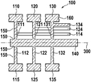
- FIG. 1 is a sectional view of a slipring module configured according to a first embodiment.
- FIG. 2 shows a side view of the first embodiment.
- FIG. 3 shows a monolithic sliding track component
- FIG. 4 shows a sectional side view of the monolithic sliding track component.
- FIG. 5 shows a front view of the monolithic sliding track component.
- FIG. 6 illustrates the slipring module after it has been removed from the mold.
- FIG. 7 shows a side view of the monolithic sliding track component.
- FIG. 8 shows a related embodiment of the invention.
- FIG. 9 shows a sectional front view through a section of the sliding track.
- FIG. 10 shows a side view of the molding.
- FIG. 11 depicts a specific embodiment of a sliding track.
- FIG. 12 illustrates sliding tracks with holding protrusions.
- FIG. 13 presents a brush block.
- a slipring module according to a first embodiment is shown in a sectional view.
- At least one sliding track 110 , 120 , 130 is at least partially embedded into an insulating body 200 .
- This embodiment shows three sliding tracks, there is no limitation on the number of sliding tracks.
- a simple module may include only one sliding track, whereas complex modules may include a large number of sliding tracks.
- the sliding tracks shown here are of the same size, but sliding tracks of different sizes may be combined in a single module.
- the sliding tracks may have different widths, different thicknesses, or even different diameters.
- the slipring module has a rotation axis 300 , which most preferably is the same axis as the center axis of the individual sliding tracks 110 , 120 , 130 .
- the sliding tracks are co-axial with the rotation axis of the slipring module.
- the sliding tracks and connectors shown herein are monolithic, single-piece components.
- the monolithic structure of the sliding track components is preferably made via 3D printing with the use of a 3D printer.
- Such a 3D printing process may be a process of dissipating multiple layers of a material to generate a predetermined three-dimensional structure.
- Such process may include at least one of the EBM, LEMS, SLM, SLS.
- FIG. 2 a sectional side view of the first embodiment of FIG. 1 is shown.
- the front ends of connectors 114 , 124 , and 134 can be seen extending through the insulating body 200 .
- a monolithic sliding track component 100 according to a first embodiment is shown.
- the first 110 , second 120 and third 130 sliding tracks (having first sliding surface 115 , second sliding surface 125 and third sliding surface 135 , respectively) are held in a fixed spatial relationship with the first and second struts 111 , 112 of the first sliding track 110 , first and second struts 121 , 122 of the second sliding track 120 , and first and second struts 131 , 132 of the third sliding track 130 .
- These struts are further held with a main support 140 (which may for example be configured as a rod extending along the rotation axis 300 ).
- first, second and/or third connectors 114 , 124 , 134 configured to electrically connect the sliding tracks.
- at least one fracture point or element or feature 150 is formed at least one of the struts, to allow for separation of the struts from the sliding tracks at the location of the fracture element, to avoid electrical short circuiting.
- the connectors 114 , 124 , 134 may be connected to a given sliding track at any point, as long as such connection(s) provide good electrical contact. For example, as shown the connector 134 is connected to the sliding track 130 at an upper section of the first strut 131 .
- the connectors 114 and 124 are connected directly to the corresponding sliding tracks to provide a spatial offset(s) from the connector 134 .
- at least one of the sliding tracks (and most preferably all sliding tracks) is equipped with a holding structure 160 , preferably at the side of the corresponding sliding track.
- such holding structure 160 may include recesses 201 and/or protrusions 161 .
- the holding structure 160 includes a V-shaped recess (groove).
- the insulating material e.g. a plastic material
- FIG. 4 a sectional side view of the monolithic sliding track component is shown in a mold after the mold has been filled with an insulating material (e.g. a plastic material) forming the insulating body 200 .
- the mold is a two-sectioned cylindrically-shaped body having a first section 510 and a second section 520 .
- FIG. 5 a front view of the monolithic sliding track component is shown, with a cross-section through the center of the third sliding track 130 .
- FIG. 5 also clearly shows the arrangement of the struts 131 and 132 .
- the other struts 111 , 121 , 112 , 122 are not visible in this view because they are hidden (blocked from view) by the struts 131 and 132 .
- an embodiment of the slipring module is shown in a sectional view after it has been removed from the mold 500 .
- an insulating body 200 is formed by the insulating material, e.g. a cured plastic material.
- the struts and the main support 140 have to be removed to avoid short-circuiting of the sliding tracks. This may easily be done by moving the main support 140 into the direction of the rotation axis 300 . Such movement, when implemented, would bend the struts and cause the struts to break at the fracture points 150 of the main support 140 and the sliding tracks. The appropriate movement may easily be carried out by pushing or knocking a bolt against the main support 140 or by pushing the slipring module with its main support 140 on a flat surface) with the main support extending over one side of the slipring module as shown).
- any tests or modification may be done which require an electrical connection of the sliding tracks.
- a common electrical test may be performed, or the sliding tracks may be galvanized or anodized, for which the main support may be a common electrode connection.
- FIG. 7 a side view of an embodiment of the monolithic sliding track component is shown, with a cross-section through the center of the third sliding track 130 .
- FIG. 7 also clearly shows the arrangement of the struts 131 and 132 .
- the other struts 111 , 121 , 112 , 122 are not visible because they are hidden (blocked from view) by the struts 131 and 132 .
- FIG. 8 a related embodiment of the monolithic sliding track component 101 is shown.
- the struts have a different design than in the previous embodiment. Whereas in the previous embodiment only two struts were used to hold/affix a sliding track to the main support, in the embodiment of FIG. 8 three struts are used for the same purpose. Structural details of the struts can be appreciated from the following FIG. 9 , which shows a front cross-sectional view drawn through the sliding track 130 .
- first sliding track 110 is held by the first strut 111 , second strut 112 , and third strut 113 , which are only shown in FIG. 9 .
- connector 114 configured to electrically connect the first sliding track 110 to another component.
- a second sliding track 120 is held by the first strut 121 , second strut 122 , and third strut 123 , which is also shown in FIG. 9 .
- a connector 124 is provided and configured to connect the second sliding track 120 .
- Third sliding track 130 is held by a first strut 131 , a second strut 132 , and a third strut 133 , which is shown in FIG. 9 .
- a connector 134 is provided and configured to connect the first sliding track 130 .
- FIG. 9 a cross-sectional front view through a section of the sliding track 130 is presented.
- FIG. 9 shows all the struts configured to hold the sliding tracks.
- FIG. 10 a side view of the molded module is shown. Here, portions of the struts are shown embedded into the insulating material 200 .
- FIG. 11 a specific embodiment of a sliding track is shown with a V-groove 170 at its sliding surface.
- FIG. 12 illustrates sliding tracks with holding protrusions 161 extending from the inner side of the sliding tracks. Such holding protrusions are later (during the fabrication process) embedded into the insulating body material 200 to firmly hold the sliding tracks in place.
- a brush holder 600 is shown as a monolithic, single-piece component, which most preferably is made by a 3D printing process by a 3D printer as mentioned above.
- the brush holder 600 includes a brush holder body 601 that has at least a first brush contact 602 and a second brush contact 603 .
- the brush contacts establish contact(s) with and/or hold at least a first brush wire 610 and/or a second brush wire 611 .
- the brush contacts are oriented such, that the brush wire extends the brush holder body at a certain angle that is different from 90° to provide desired pressure to a sliding track, in operation.
- Electrical contact between the brush wires and the brush holder body may be established by crimping, soldiering, welding or any other suitable method.
- Multiple brush holders may be assembled to a brush block. This embodiment may be combined with at least one of the embodiments mentioned above.
Landscapes
- Engineering & Computer Science (AREA)
- Manufacturing & Machinery (AREA)
Abstract
-
- making a monolithic sliding track component preferably by a 3D printing process. The monolithic sliding track component comprises a plurality of sliding tracks, multiple connector for electrically connecting the sliding tracks, and at least one strut for mechanically interconnecting the sliding tracks and the connector to form a monolithic sliding track component;
- inserting the monolithic sliding track component into a mold;
- filling the mold with an insulating material such as a plastic material, and curing the plastic material;
- removing the molded product forming a slipring module from the mold, and
- removing the at least one strut from the slipring module.
Description
-
- making a monolithic sliding track component preferably by a 3D printing process. The monolithic sliding track component includes at least one sliding track and at least one connector configured to electrically connect the sliding track;
- inserting at least one of the monolithic sliding track components into a mold;
- filling the mold with an insulating material such as a plastic material, and curing the plastic material;
- removing the molded product forming a slipring module from the mold.
-
- making a monolithic sliding track component preferably by a 3D printing process. The monolithic sliding track component includes at least two sliding tracks, at least one connector configured to electrically connect each of the sliding tracks, and at least one strut configured to mechanically connect the sliding tracks and the connector to form a monolithic sliding track component;
- inserting at least one of the monolithic sliding track components into a mold;
- filling the mold with an insulating material such as a plastic material, and curing the plastic material;
- removing the molded product forming a slipring module from the mold;
- removing the at least one strut from the slipring module.
- 100 monolithic sliding track component
- 101 monolithic sliding track component
- 110 first sliding track
- 111 first strut
- 112 second strut
- 113 third strut
- 114 first connector
- 115 first sliding surface
- 120 second sliding track
- 121 first strut
- 122 second strut
- 123 third strut
- 124 second connector
- 125 second sliding surface
- 130 third sliding track
- 131 first strut
- 132 second strut
- 133 third strut
- 134 third connector
- 135 third sliding surface
- 140 main support
- 150 fracture point
- 160 holding structure
- 161 holding protrusion
- 170 V-groove
- 200 insulating body
- 201 recess
- 300 rotation axis
- 500 mold
- 510 first mold section
- 520 second mold section
- 600 brush holder
- 601 brush holder body
- 602 first brush contact
- 603 second brush contact
- 608 threaded hole
- 610 first brush wire
- 611 second brush wire
Claims (20)
Applications Claiming Priority (4)
| Application Number | Priority Date | Filing Date | Title |
|---|---|---|---|
| EP16195609 | 2016-10-25 | ||
| EP16195609.9 | 2016-10-25 | ||
| EP16195609.9A EP3316425A1 (en) | 2016-10-25 | 2016-10-25 | Slip ring module |
| PCT/EP2017/077346 WO2018077970A1 (en) | 2016-10-25 | 2017-10-25 | Slip ring module |
Related Parent Applications (1)
| Application Number | Title | Priority Date | Filing Date |
|---|---|---|---|
| PCT/EP2017/077346 Continuation WO2018077970A1 (en) | 2016-10-25 | 2017-10-25 | Slip ring module |
Publications (2)
| Publication Number | Publication Date |
|---|---|
| US20190245312A1 US20190245312A1 (en) | 2019-08-08 |
| US11217952B2 true US11217952B2 (en) | 2022-01-04 |
Family
ID=57206104
Family Applications (1)
| Application Number | Title | Priority Date | Filing Date |
|---|---|---|---|
| US16/385,986 Active 2038-05-19 US11217952B2 (en) | 2016-10-25 | 2019-04-16 | Slip ring module |
Country Status (4)
| Country | Link |
|---|---|
| US (1) | US11217952B2 (en) |
| EP (2) | EP3316425A1 (en) |
| CN (1) | CN109863652B (en) |
| WO (1) | WO2018077970A1 (en) |
Families Citing this family (7)
| Publication number | Priority date | Publication date | Assignee | Title |
|---|---|---|---|---|
| WO2019141351A1 (en) | 2018-01-16 | 2019-07-25 | CSEM Centre Suisse d'Electronique et de Microtechnique SA - Recherche et Développement | Method for manufacturing a 3d electromechanical component having at least one embedded electrical conductor |
| EP3641076B1 (en) | 2018-10-19 | 2020-09-30 | Schleifring GmbH | Slipring housing with bayonet lock |
| TWI699945B (en) * | 2019-04-12 | 2020-07-21 | 泓記精密股份有限公司 | Slip ring rotor module and manufacturing method thereof |
| CN113875099B (en) | 2019-06-14 | 2022-06-28 | 史莱福灵有限公司 | Slip ring device |
| CN111009793B (en) * | 2019-12-10 | 2023-01-13 | 中船航海科技有限责任公司 | Miniature conducting ring assembly and preparation method thereof |
| EP4343986A1 (en) * | 2022-09-26 | 2024-03-27 | Dr. Johannes Heidenhain GmbH | Slip ring module |
| CN117895304B (en) * | 2024-03-14 | 2024-05-28 | 北京微动时空科技有限公司 | Integrated device and method for forming conductive slip ring brush wire and detecting deformation |
Citations (13)
| Publication number | Priority date | Publication date | Assignee | Title |
|---|---|---|---|---|
| US2961385A (en) * | 1958-06-30 | 1960-11-22 | Breeze Corp | Method of forming slip-rings in annular grooves |
| US2967283A (en) * | 1957-07-17 | 1961-01-03 | Lamtex Ind Inc | Slip ring assembly and method of making the same |
| US3126596A (en) * | 1964-03-31 | Cast slip-ring assembly | ||
| US3182217A (en) | 1962-12-03 | 1965-05-04 | Zyrotron Ind Inc | Commutating apparatus |
| US3219557A (en) * | 1962-04-12 | 1965-11-23 | Pacific Scientific Co | Method of producing a rotary coupling |
| US3289140A (en) | 1962-02-26 | 1966-11-29 | Borg Warner | Slip ring assembly |
| US3435402A (en) | 1966-03-30 | 1969-03-25 | Borg Warner | Slip ring assembly and process of manufacturing same |
| EP0618648A1 (en) | 1993-03-30 | 1994-10-05 | Air Precision S.A. | Process for manufacturing a rotor of a rotating electrical collector |
| US6283638B1 (en) | 1998-07-31 | 2001-09-04 | Litton Systems, Inc. | Slip ring with integral bearing assembly and method of manufacture |
| US20040242025A1 (en) | 2003-05-30 | 2004-12-02 | Ludwig Angerpointner | Slip-ring element and method for its manufacture |
| US6836049B2 (en) * | 2002-12-04 | 2004-12-28 | Asmo Co., Ltd. | Commutator having short-circuiting parts, motor having such a commutator and method for manufacturing such a commutator |
| US20140084745A1 (en) * | 2012-09-21 | 2014-03-27 | Asmo Co., Ltd. | Commutator |
| US9209572B1 (en) | 2014-07-28 | 2015-12-08 | Tyco Electronics Corporation | Pluggable connector configured to reduce electromagnetic interference leakage |
Family Cites Families (5)
| Publication number | Priority date | Publication date | Assignee | Title |
|---|---|---|---|---|
| US5734218A (en) | 1996-05-13 | 1998-03-31 | Litton Systems, Inc. | Electrical slip ring and method of manufacturing same |
| US6359362B1 (en) * | 2000-07-31 | 2002-03-19 | Mccord Winn Textron Inc. | Planar commutator segment attachment method and assembly |
| DE10250261A1 (en) * | 2002-10-28 | 2004-06-09 | Kolektor D.O.O. | Commutator for an electrical machine and method for its production |
| CN101924315B (en) * | 2009-06-16 | 2014-09-03 | 德昌电机(深圳)有限公司 | Commutator and manufacturing method thereof |
| CN104067488B (en) | 2012-03-08 | 2017-06-09 | 三菱电机株式会社 | The rotor of electric rotating machine |
-
2016
- 2016-10-25 EP EP16195609.9A patent/EP3316425A1/en not_active Withdrawn
-
2017
- 2017-10-25 WO PCT/EP2017/077346 patent/WO2018077970A1/en not_active Ceased
- 2017-10-25 CN CN201780066025.3A patent/CN109863652B/en active Active
- 2017-10-25 EP EP17791061.9A patent/EP3533116A1/en active Pending
-
2019
- 2019-04-16 US US16/385,986 patent/US11217952B2/en active Active
Patent Citations (13)
| Publication number | Priority date | Publication date | Assignee | Title |
|---|---|---|---|---|
| US3126596A (en) * | 1964-03-31 | Cast slip-ring assembly | ||
| US2967283A (en) * | 1957-07-17 | 1961-01-03 | Lamtex Ind Inc | Slip ring assembly and method of making the same |
| US2961385A (en) * | 1958-06-30 | 1960-11-22 | Breeze Corp | Method of forming slip-rings in annular grooves |
| US3289140A (en) | 1962-02-26 | 1966-11-29 | Borg Warner | Slip ring assembly |
| US3219557A (en) * | 1962-04-12 | 1965-11-23 | Pacific Scientific Co | Method of producing a rotary coupling |
| US3182217A (en) | 1962-12-03 | 1965-05-04 | Zyrotron Ind Inc | Commutating apparatus |
| US3435402A (en) | 1966-03-30 | 1969-03-25 | Borg Warner | Slip ring assembly and process of manufacturing same |
| EP0618648A1 (en) | 1993-03-30 | 1994-10-05 | Air Precision S.A. | Process for manufacturing a rotor of a rotating electrical collector |
| US6283638B1 (en) | 1998-07-31 | 2001-09-04 | Litton Systems, Inc. | Slip ring with integral bearing assembly and method of manufacture |
| US6836049B2 (en) * | 2002-12-04 | 2004-12-28 | Asmo Co., Ltd. | Commutator having short-circuiting parts, motor having such a commutator and method for manufacturing such a commutator |
| US20040242025A1 (en) | 2003-05-30 | 2004-12-02 | Ludwig Angerpointner | Slip-ring element and method for its manufacture |
| US20140084745A1 (en) * | 2012-09-21 | 2014-03-27 | Asmo Co., Ltd. | Commutator |
| US9209572B1 (en) | 2014-07-28 | 2015-12-08 | Tyco Electronics Corporation | Pluggable connector configured to reduce electromagnetic interference leakage |
Non-Patent Citations (1)
| Title |
|---|
| International Search Report and Written Opinion issued in International Patent Application PCT/EP2017/077346, dated Dec. 15, 2017, 15 pages. |
Also Published As
| Publication number | Publication date |
|---|---|
| EP3316425A1 (en) | 2018-05-02 |
| WO2018077970A1 (en) | 2018-05-03 |
| CN109863652B (en) | 2022-02-01 |
| EP3533116A1 (en) | 2019-09-04 |
| CN109863652A (en) | 2019-06-07 |
| US20190245312A1 (en) | 2019-08-08 |
Similar Documents
| Publication | Publication Date | Title |
|---|---|---|
| US11217952B2 (en) | Slip ring module | |
| JP6965848B2 (en) | Coil parts | |
| EP1227554B1 (en) | Rotation connector and a method of making such a connector | |
| CN108573800B (en) | Coil component | |
| US10611139B2 (en) | Method for producing at least one spring contact pin or a spring contact pin arrangement, and corresponding devices | |
| JP6865605B2 (en) | Common mode choke coil | |
| EP3270468A1 (en) | Slip ring assembly | |
| EP3293836B1 (en) | Methods of making contact wires for sliprings, device for manufacturing of contact wires for sliprings and contact wires for sliprings | |
| US20180261365A1 (en) | Coil component | |
| US10775416B2 (en) | Method for producing a contact spacing converter and contact spacing converter | |
| US11496014B2 (en) | Winding head arrangement for an electric rotating machine | |
| US12528254B2 (en) | Method for manufacturing a 3D electromechanical component having at least one embedded electrical conductor | |
| US10222436B2 (en) | Gradient coil and manufacturing method | |
| CN106415755B (en) | Manufacturing method of wound type coil component | |
| US11522418B2 (en) | Bent conductor segment for a stator winding of a stator of an electric machine | |
| CN112310776A (en) | Production of a flat connection between an electrical conductor and a contact | |
| US3014193A (en) | Electrical slip ring and support | |
| US11901783B2 (en) | Method for producing a winding overhang assembly for an electrical rotating machine | |
| JP2020074486A (en) | Coil component | |
| EP0577314A2 (en) | Split coaxial cable conductor and method of fabrication | |
| JPS6355850B2 (en) | ||
| US20050022367A1 (en) | Method of fabricating a commutator for a motor | |
| CN1933034B (en) | Insulating coated wire and its producing method, insulating coated wire product and its producing method | |
| RU2446505C1 (en) | Method to manufacture cathode for microwave device | |
| JP2023120748A (en) | Inductor and inductor manufacturing method |
Legal Events
| Date | Code | Title | Description |
|---|---|---|---|
| FEPP | Fee payment procedure |
Free format text: ENTITY STATUS SET TO UNDISCOUNTED (ORIGINAL EVENT CODE: BIG.); ENTITY STATUS OF PATENT OWNER: LARGE ENTITY |
|
| AS | Assignment |
Owner name: SCHLEIFRING GMBH, GERMANY Free format text: ASSIGNMENT OF ASSIGNORS INTEREST;ASSIGNOR:HOLZAPFEL, CHRISTIAN;REEL/FRAME:049736/0588 Effective date: 20190703 |
|
| STPP | Information on status: patent application and granting procedure in general |
Free format text: DOCKETED NEW CASE - READY FOR EXAMINATION |
|
| STPP | Information on status: patent application and granting procedure in general |
Free format text: NON FINAL ACTION MAILED |
|
| STPP | Information on status: patent application and granting procedure in general |
Free format text: RESPONSE TO NON-FINAL OFFICE ACTION ENTERED AND FORWARDED TO EXAMINER |
|
| STPP | Information on status: patent application and granting procedure in general |
Free format text: FINAL REJECTION MAILED |
|
| STPP | Information on status: patent application and granting procedure in general |
Free format text: RESPONSE AFTER FINAL ACTION FORWARDED TO EXAMINER |
|
| STPP | Information on status: patent application and granting procedure in general |
Free format text: NOTICE OF ALLOWANCE MAILED -- APPLICATION RECEIVED IN OFFICE OF PUBLICATIONS |
|
| STPP | Information on status: patent application and granting procedure in general |
Free format text: PUBLICATIONS -- ISSUE FEE PAYMENT VERIFIED |
|
| STCF | Information on status: patent grant |
Free format text: PATENTED CASE |
|
| MAFP | Maintenance fee payment |
Free format text: PAYMENT OF MAINTENANCE FEE, 4TH YEAR, LARGE ENTITY (ORIGINAL EVENT CODE: M1551); ENTITY STATUS OF PATENT OWNER: LARGE ENTITY Year of fee payment: 4 |