US11217923B2 - Plug-in structure, connector, plug, and plug-in method thereof - Google Patents
Plug-in structure, connector, plug, and plug-in method thereof Download PDFInfo
- Publication number
- US11217923B2 US11217923B2 US16/915,022 US202016915022A US11217923B2 US 11217923 B2 US11217923 B2 US 11217923B2 US 202016915022 A US202016915022 A US 202016915022A US 11217923 B2 US11217923 B2 US 11217923B2
- Authority
- US
- United States
- Prior art keywords
- plug
- guide rail
- rail structure
- terminal
- strip
- Prior art date
- Legal status (The legal status is an assumption and is not a legal conclusion. Google has not performed a legal analysis and makes no representation as to the accuracy of the status listed.)
- Active
Links
Images


Classifications
-
- H—ELECTRICITY
- H01—ELECTRIC ELEMENTS
- H01R—ELECTRICALLY-CONDUCTIVE CONNECTIONS; STRUCTURAL ASSOCIATIONS OF A PLURALITY OF MUTUALLY-INSULATED ELECTRICAL CONNECTING ELEMENTS; COUPLING DEVICES; CURRENT COLLECTORS
- H01R12/00—Structural associations of a plurality of mutually-insulated electrical connecting elements, specially adapted for printed circuits, e.g. printed circuit boards [PCB], flat or ribbon cables, or like generally planar structures, e.g. terminal strips, terminal blocks; Coupling devices specially adapted for printed circuits, flat or ribbon cables, or like generally planar structures; Terminals specially adapted for contact with, or insertion into, printed circuits, flat or ribbon cables, or like generally planar structures
- H01R12/70—Coupling devices
- H01R12/77—Coupling devices for flexible printed circuits, flat or ribbon cables or like structures
- H01R12/771—Details
-
- H—ELECTRICITY
- H01—ELECTRIC ELEMENTS
- H01R—ELECTRICALLY-CONDUCTIVE CONNECTIONS; STRUCTURAL ASSOCIATIONS OF A PLURALITY OF MUTUALLY-INSULATED ELECTRICAL CONNECTING ELEMENTS; COUPLING DEVICES; CURRENT COLLECTORS
- H01R12/00—Structural associations of a plurality of mutually-insulated electrical connecting elements, specially adapted for printed circuits, e.g. printed circuit boards [PCB], flat or ribbon cables, or like generally planar structures, e.g. terminal strips, terminal blocks; Coupling devices specially adapted for printed circuits, flat or ribbon cables, or like generally planar structures; Terminals specially adapted for contact with, or insertion into, printed circuits, flat or ribbon cables, or like generally planar structures
- H01R12/70—Coupling devices
- H01R12/77—Coupling devices for flexible printed circuits, flat or ribbon cables or like structures
- H01R12/78—Coupling devices for flexible printed circuits, flat or ribbon cables or like structures connecting to other flexible printed circuits, flat or ribbon cables or like structures
-
- H—ELECTRICITY
- H01—ELECTRIC ELEMENTS
- H01R—ELECTRICALLY-CONDUCTIVE CONNECTIONS; STRUCTURAL ASSOCIATIONS OF A PLURALITY OF MUTUALLY-INSULATED ELECTRICAL CONNECTING ELEMENTS; COUPLING DEVICES; CURRENT COLLECTORS
- H01R12/00—Structural associations of a plurality of mutually-insulated electrical connecting elements, specially adapted for printed circuits, e.g. printed circuit boards [PCB], flat or ribbon cables, or like generally planar structures, e.g. terminal strips, terminal blocks; Coupling devices specially adapted for printed circuits, flat or ribbon cables, or like generally planar structures; Terminals specially adapted for contact with, or insertion into, printed circuits, flat or ribbon cables, or like generally planar structures
- H01R12/70—Coupling devices
- H01R12/77—Coupling devices for flexible printed circuits, flat or ribbon cables or like structures
-
- H—ELECTRICITY
- H01—ELECTRIC ELEMENTS
- H01R—ELECTRICALLY-CONDUCTIVE CONNECTIONS; STRUCTURAL ASSOCIATIONS OF A PLURALITY OF MUTUALLY-INSULATED ELECTRICAL CONNECTING ELEMENTS; COUPLING DEVICES; CURRENT COLLECTORS
- H01R13/00—Details of coupling devices of the kinds covered by groups H01R12/70 or H01R24/00 - H01R33/00
- H01R13/62—Means for facilitating engagement or disengagement of coupling parts or for holding them in engagement
- H01R13/629—Additional means for facilitating engagement or disengagement of coupling parts, e.g. aligning or guiding means, levers, gas pressure electrical locking indicators, manufacturing tolerances
- H01R13/631—Additional means for facilitating engagement or disengagement of coupling parts, e.g. aligning or guiding means, levers, gas pressure electrical locking indicators, manufacturing tolerances for engagement only
Definitions
- the present disclosure relates to the field of electrical devices, and more particularly to a plug-in structure, a connector, a plug, and a plug-in method thereof.
- the connector is electrically connected to one flexible circuit board, and the plug is electrically connected to the other flexible circuit board.
- an operator uses tweezers to clamp a position of the flexible circuit board proximal to the plug, and the plug is plugged into a jack of the connector after the plug is aligned with the jack of the connector, such that the plug is plugged into the connector.
- the present disclosure provides a plug-in structure, a connector, a plug, and a plug-in method.
- a plug-in structure in a first aspect, includes a connector and a plug.
- the connector is provided with a jack; wherein the jack is provided with a first terminal and a first guide rail structure, the first terminal is configured to be electrically connected to a first flexible circuit board; and
- the plug is provided with a second terminal and a second guide rail structure; wherein the second terminal is configured to be electrically connected to a second flexible circuit board, and the second guide rail structure of the plug is in cooperation with the first guide rail structure in the jack to guide the plug to move in the jack, such that the first terminal is electrically connected to the second terminal.
- the first guide rail structure includes a strip-shaped protrusion
- the second guide rail structure includes a strip-shaped groove
- corners of both the strip-shaped protrusion and the strip-shaped groove are chamfered.
- the jack is a square hole enclosed by two opposite side surfaces and two opposite bottom surfaces.
- the first guide rail structure is disposed on the two side surfaces.
- the plug includes a substrate layer; wherein the substrate layer is enclosed by a first surface and a second surface opposite to each other as well as a side surface connected to both the first surface and the second surface; the second terminal is disposed on the first surface; and the second guide rail structure is disposed on the side surface.
- the first guide rail structure is disposed on one of the two bottom surfaces.
- the plug includes a substrate layer; wherein the substrate layer is enclosed by a first surface and a second surface opposite to each other as well as a side surface connected to both the first surface and the second surface; the second terminal is disposed on the first surface; and the second guide rail structure is disposed on the second surface.
- a material of the substrate layer includes polyimide.
- a material of the strip-shaped protrusion includes polyterephthalate plastic.
- a plug-in method of the above plug-in structure includes:
- a connector is provided.
- the connector is provided with a jack.
- the jack is provided with a first terminal and a first guide rail structure; wherein the first terminal is configured to be electrically connected to a first flexible circuit board.
- a plug is provided.
- the plug is provided with a second terminal and a second guide rail structure; wherein the second terminal is configured to be electrically connected to a second flexible circuit board.
- the first guide rail structure includes a strip-shaped groove
- the second guide rail structure includes a strip-shaped protrusion
- corners of both the strip-shaped protrusion and the strip-shaped groove are rounded.
- a material of the substrate layer includes polyimide.
- the first guide rail structure includes a strip-shaped protrusion
- the second guide rail structure includes a strip-shaped groove; wherein corners of both the strip-shaped protrusion and the strip-shaped groove are rounded, and a material of the strip-shaped protrusion includes polyterephthalate plastic;
- the jack is a square hole enclosed by two opposite side surfaces and two opposite bottom surfaces, and the first guide rail structure is disposed on the two side surfaces;
- the plug includes a substrate layer; wherein the substrate layer is enclosed by a first surface and a second surface opposite to each other as well as a side surface connected to both the first surface and the second surface, the second terminal is disposed on the first surface, the second guide rail structure is disposed on the side surface, and a material of the substrate layer includes polyimide.
- the jack is a square hole enclosed by two opposite side surfaces and two opposite bottom surfaces, and the first guide rail structure is disposed on the two side surfaces.
- the plug includes a substrate layer; wherein the substrate layer is enclosed by a first surface and a second surface opposite to each other as well as a side surface connected to both the first surface and the second surface; the second terminal is disposed on the first surface; and the second guide rail structure is disposed on the side surface.
- the plug includes a substrate layer, and the substrate layer is enclosed by a first surface and a second surface opposite to each other as well as a side surface connected to both the first surface and the second surface; the second terminal is disposed on the first surface; and the second guide rail structure is disposed on the second surface.
- FIG. 1 is a schematic diagram of a plug-in structure according to an embodiment of the present disclosure in a separated state
- FIG. 2 is a schematic diagram of the plug-in structure according to the embodiment of the present disclosure in a plug-in completed state;
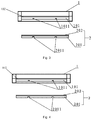
- FIGS. 3 and 4 are schematic diagrams of two different guide rail structure arrangements of the plug-in structure according to the embodiment of the present disclosure.
- FIG. 5 is a flow chart of a plug-in method according to an embodiment of the present disclosure.
- a conventional portable device typically includes a plurality of flexible circuit boards.
- an organic light-emitting diode (OLED) display device or a liquid crystal display (LCD) device generally includes at least two flexible circuit boards, namely, a touch flexible printed circuit board (TFPC) and a main flexible printed circuit board (MFPC).
- TFPC touch flexible printed circuit board
- MFPC main flexible printed circuit board
- the conventional flexible circuit boards are generally connected by a connector and a plug.
- a connector according to the embodiments of the present disclosure may be a zero insertion force (ZIF) connector or a non-zero insertion force (non-ZIF) connector, and a plug in the embodiments of the present disclosure may be a connecting finger.
- ZIF zero insertion force
- non-ZIF non-zero insertion force
- a plugging direction refers to a movement direction of a plug 2 relative to a connector 1 in a process that the plug 2 is plugged into a jack 101 of the connector 1 .
- An embodiment of the present disclosure provides a plug-in structure. As shown in FIG. 1 , the plug-in structure includes a connector 1 and a plug 2 .
- the connector 1 is provided with a jack 101 .
- the jack 101 is provided with a first terminal 102 and a first guide rail structure 1011 are arranged.
- the first terminal 102 is configured to be electrically connected to a first flexible circuit board 1012 .
- the plug 2 is provided with a second terminal 202 and a second guide rail structure 2011 .
- the second terminal 202 is configured to be electrically connected to a second flexible circuit board 2012 .
- the second guide rail structure 2011 of the plug 2 is in cooperation with the first guide rail structure 1011 in the jack 101 to guide movement of the plug 2 in the jack 101 , such that the first terminal and the second terminal 202 are electrically connected. That is, the second guide rail structure 2011 is configured to be in cooperation with the first guide rail structure 1011 in a process of plugging of the plug 2 into the jack 101 of the connector 1 , and the first terminal and the second terminal 202 are electrically connected after the plug 2 is plugged into the jack 101 of the connector 1 .
- the plug-in structure includes the connector and the plug, wherein the connector is provided with the jack, the jack is provided with the first terminal and the first guide rail structure, and the first terminal may be electrically connected to the first flexible circuit board.
- the plug is provided with the second terminal and the second guide rail structure.
- the second terminal 202 may be electrically connected to the second flexible circuit board.
- the second guide rail structure of the plug may be in cooperation with the first guide rail structure in the jack to guide the plug to continue to be plugged into the jack, such that the plug is smoothly plugged into the jack of the connector and thus the first flexible circuit board is in communication with the second flexible circuit board. In this way, damages caused by a clamping tool (such as tweezers) to the flexible circuit boards are prevented.
- the plug-in structure in FIG. 1 is in a separated state where the plug is not completely plugged into the connector and the first flexible circuit board and the second flexible circuit board are not conducted.
- the connector 1 is provided with the jack 101 in which the first terminal (not shown in the figure) and the first guide rail structure 1011 are arranged; and the first terminal is configured to be electrically connected to the first flexible circuit board, and may a single-row terminal or a double-row terminal.
- the plug 2 includes a substrate layer 201 .
- the substrate layer 201 is enclosed by a first surface and a second surface (the first surface and the second surface may be the upper surface and the lower surface of the substrate layer 201 shown in FIG. 1 , respectively) opposite to each other as well as a side surface connected to both the first surface and the second surface.
- the second terminal 202 is disposed on the first surface.
- the second guide rail structure 2011 is disposed on the side surface.
- the second terminal 202 is a single-row terminal or a double-row terminal.
- the first surface and the second surface of the substrate layer may be two identical surfaces at different positions, and the surface where the second terminal is disposed may be the first surface.
- a material of the substrate layer 201 includes polyimide, and the substrate layer 201 overlaps with the second terminal 202 .
- the substrate layer 201 is configured to increase the thickness and strength of the plug 2 to facilitate plugging.
- the second terminal 202 is configured to be electrically connected to a second flexible circuit board.
- the second guide rail structure 2011 is configured to be in cooperation with the first guide rail structure 1011 in a process of plugging of the plug 2 into the jack 101 of the connector 1 , and the first terminal and the second terminal 202 are electrically connected after the plug 2 is plugged into the jack 101 of the connector 1 .
- FIG. 2 shows a schematic diagram of a structure when the plug 2 is plugged into the connector 1 in the plug-in structure shown in FIG. 1 .
- the first terminal is electrically connected to the first flexible circuit board and the second terminal 202 is electrically connected to the second flexible circuit board
- the first flexible circuit board and the second flexible circuit board are electrically connected. That is, an electrical connection between the first flexible circuit board and the second flexible circuit board is successfully established.
- the jack 101 is a square hole enclosed by two opposite side surfaces and two opposite bottom surfaces.
- the two side surfaces and the two opposite bottom surfaces are the inner surfaces of the jack 101 .
- the first terminal is disposed inside the jack 101 of the connector 1 , and is disposed on one of the bottom surfaces (such as the upper bottom surface or the lower bottom surface in FIG. 1 ) inside the jack 101 .
- first guide rail structure 1011 and the second guide rail structure 2011 there are two position arrangements for the first guide rail structure 1011 and the second guide rail structure 2011 as follows.
- the first guide rail structure 1011 is disposed on the two side surfaces which refer to the two side surfaces of the jack 101 herein.
- the second guide rail structure 2011 is disposed on the side surfaces of the substrate layer 201 .
- the first guide rail structure 1011 is disposed on the two side surfaces of the jack 101 of the connector 1 ; the second guide rail structure 2011 is disposed on the two side surfaces of the substrate layer 201 of the plug 2 ; and the surfaces where the first guide rail structure 1011 is disposed correspond to the surfaces where the second guide rail structure 2011 is disposed, such that the positions of the first guide rail structure 1011 and the second guide rail structure 2011 may be in cooperation with each other.
- Length directions of both the first guide rail structure 1011 and the second guide rail structure 2011 are parallel to the plugging direction.
- the first guide rail structure 1011 is disposed on one of the two bottom surfaces.
- the first guide rail structure 1011 may be arranged on the other bottom surface in the two bottom surfaces inside the jack 101 of the connector 1 where the first terminal is not arranged.
- the plug 2 includes a substrate layer 201 .
- the substrate layer 201 is enclosed by a first surface and a second surface (the first surface and the second surface may be the upper surface and the lower surface of the substrate layer 201 shown in FIG. 1 , respectively) opposite to each other as well as a side surface connected to both the first surface and the second surface.
- the second terminal 202 is disposed on the first surface.
- the second guide rail structure 2011 is disposed on the second surface opposite to the first surface where the second terminal 201 is disposed.
- the substrate layer 201 overlaps with the second terminal 202 .
- the substrate layer 201 is further provided with two surfaces (i.e., the first surface and the second surface) in addition to the side surface, wherein one surface (i.e., the first surface) faces the second terminal 202 and is connected to the second terminal 202 , and the other surface (i.e., the second surface) faces away from the second terminal 202 and is opposite to the surface where the second terminal 202 is disposed.
- the second guide rail structure 2011 is arranged on the surface of the substrate layer 201 opposite to the surface where the second terminal 202 is disposed.
- the first guide rail structure 1011 is disposed on one bottom surface of the jack 101 of the connector 1 ; the second guide rail structure 2011 is disposed on the other bottom surface of the substrate layer 201 of the plug 2 opposite to the surface where the second terminal 202 is disposed; and the surface where the first guide rail structure 1011 is disposed corresponds to the surface where the second guide rail structure 2011 is disposed, such that the positions of the first guide rail structure 1011 and the second guide rail structure 2011 may be in cooperation with each other.
- both the first guide rail structure 1011 and the second guide rail structure 2011 are parallel to the plugging direction.
- Structures of both the first guide rail structure 1011 and the second guide rail structure 2011 are suitable for cooperation with each other, and specific mutual cooperation may include the followings.
- the first guide rail structure 1011 includes a strip-shaped protrusion
- the second guide rail structure 2011 includes a strip-shaped groove. Structures of both the strip-shaped protrusion and the strip-shaped groove are suitable for cooperation with each other. That is, the strip-shaped protrusion of the first guide rail structure 1011 may be plugged into the strip-shaped groove of the second guide rail structure 2011 .
- the structures of both the strip-shaped protrusion and the strip-shaped groove are relatively simple and easy to manufacture.
- the first guide rail structure may also include protrusions of other shapes
- the second guide rail structure may also include grooves of other shapes, such as circular protrusions and circular grooves, triangular protrusions and triangular grooves, and the like, which are not limited in the embodiments of the present disclosure.
- the shape of an opening of the strip-shaped groove and the shape of a protruding end of the strip-shaped protrusion may be similar or the same.
- the shape of the strip-shaped groove is not completely complementary to that of the strip-shaped protrusion; and the size of the strip-shaped protrusion may be smaller than that of a complementary structure of the strip-shaped groove, such that a certain sliding gap is maintained during the cooperation.
- Each corner of the strip-shaped protrusion and the strip-shaped groove is chamfered, and a corner formed at an intersection of three edges is also chamfered, such that the strip-shaped protrusion and the strip-shaped groove may be in cooperation more easily. That is, the first guide rail structure 1011 and the second guide rail structure 2011 may be in cooperation more easily, such that a stress during the cooperation is reduced, the service life of the structure is prolonged, and damages caused to the surface of the strip-shaped protrusion or the strip-shaped groove during the cooperation are prevented.
- the corners of both the strip-shaped protrusion and the strip-shaped groove may are rounded, which may also facilitate the cooperation between the first guide rail structure 1011 and the second guide rail structure 2011 and may reduce a stress during the cooperation, such that the service life of the structure is prolonged.
- the strip-shaped protrusion may further have a dome which may reduce friction during the plugging in process and may improve robustness of the structure, such that the service life of the structure is prolonged.
- the material of the strip-shaped protrusion includes polyterephthalate plastic, and may be the same as the material of the connector 1 .
- the length of the second guide rail structure 2011 may be same as that of the substrate layer 201 of the plug 2 in the plugging direction. That is, two tail ends of the second guide rail structure 2011 are open and may not be blocked by the substrate layer 201 , such that a sufficiently wide range of relative sliding may be defined between the plug 2 and the jack 101 .
- the plug 2 may be smoothly plugged into a preset connection position (which may refer to a position where the first terminal and the second terminal may successfully establish an electrical connection) in the jack 101 , such that the first terminal and the second terminal 202 are successfully in contact with each other and electrically connected to each other.
- the length of the strip-shaped protrusion may be qual to or different from the length of the strip-shaped groove.
- the length of the strip-shaped protrusion is less than that of the strip-shaped groove, such that the strip-shaped protrusion may be plugged into the strip-shaped groove more easily.
- the first guide rail structure 1011 includes the strip-shaped groove
- the second guide rail structure 2011 includes the strip-shaped protrusion.
- the structures of both the strip-shaped protrusion and the strip-shaped groove are suitable for cooperation with each other. That is, the strip-shaped protrusion of the second guide rail structure 1011 may be plugged into the strip-shaped groove of the first guide rail structure 2011 .
- the shape of the strip-shaped groove is not completely complementary to that of the strip-shaped protrusion; and the size of the strip-shaped protrusion may be smaller than that of a complementary structure of the strip-shaped groove, such that a certain sliding gap is left during the cooperation.
- the corners of both the strip-shaped protrusion and the strip-shaped groove may be chamfered.
- Each corner of the strip-shaped protrusion and the strip-shaped groove is chamfered, and a corner formed at an intersection of three edges is also chamfered, such that the strip-shaped protrusion and the strip-shaped groove may be in cooperation more easily. That is, the first guide rail structure 1011 and the second guide rail structure 2011 may cooperate with each other more easily, such that a stress during the cooperation is reduced, the service life of the structure is prolonged, and damages caused to the surface of the strip-shaped protrusion or the strip-shaped groove during the cooperation are prevented.
- the corners of both the strip-shaped protrusion and the strip-shaped groove may be rounded, which may also facilitate the cooperation between the first guide rail structure 1011 and the second guide rail structure 2011 and may reduce the stress during the cooperation, such that the service life of the structure is prolonged.
- the second guide rail structure 2011 is the strip-shaped protrusion. That is, when the strip-shaped protrusion is arranged on the plug 2 , the material of the strip-shaped protrusion includes polyimide, and may be the same as that of the substrate layer 201 in the plug 2 .
- FIG. 1 shows a schematic structural diagram of the above first alternative guide rail position arrangement.
- the first guide rail structure 1011 includes two strip-shaped protrusions on the side surfaces of the jack 101
- the second guide rail structure 2011 correspondingly includes strip-shaped grooves on the two side surfaces of the substrate layer 201 .
- FIGS. 3 and 4 show section views of two other plug-in structures according to the embodiments of the present disclosure (the section may be one surface perpendicular to the plugging direction).
- FIGS. 3 and 4 show a case where the first guide rail structure 1011 includes the strip-shaped protrusion and the second guide rail structure 2011 includes the strip-shaped groove.
- the first guide rail structure 1011 may include two strip-shaped protrusions disposed on one bottom surface of the jack, and the second guide rail structure may include two strip-shaped grooves disposed on the bottom surface (i.e., the second surface) of the substrate layer 201 .
- the two strip-shaped protrusions and the two strip-shaped grooves may be in cooperation with each other to guide the plug 2 during the plugging of the plug into the jack, such that the plug 2 is plugged into the jack 101 more smoothly.
- the first guide rail structure 1011 may include one strip-shaped protrusion disposed on one bottom surface of the jack
- the second guide rail structure may include one strip-shaped groove disposed on the bottom surface (i.e., the second surface) of the substrate layer 201 .
- the strip-shaped protrusion and the strip-shaped groove may be in cooperation with each other to guide the plug 2 during the plugging of the plug into the jack, such that the plug 2 is plugged into the jack 101 more smoothly.
- This structure may also simplify the overall structure and reduce the manufacturing cost.
- the first guide rail structure may also include protrusions of other shapes
- the second guide rail structure may also include grooves of other shapes, such as circular protrusions and circular grooves, triangular protrusions and triangular grooves, and the like, which are not limited in the embodiments of the present disclosure.
- the connector 1 further includes a latch configured to fix the plug 2 in the jack 101 of the connector 1 after the first terminal and the second terminal are in successful contact with each other and establish an electrical connection at the preset connection position (which may refer to a position where the first terminal and the second terminal are electrically connected successfully) where the plug 2 has been plugged into the jack 101 of the connector 1 , so as to ensure the connection firmness.
- the fixation of the latch is specifically as follows.
- One end of the latch is rotatably arranged on the connector 1 , and a snap is arranged at the other end of the latch.
- the latch When the end with the snap is pressed down, the latch may be fixed on the connector 1 by using the snap, and meanwhile, the plug 2 is fixed in the jack 101 of the connector 1 .
- the process of plugging the plug into the connector is generally as follows.
- Tweezers are employed to clamp a position on the second flexible printed circuit board proximal to the plug, and the plug is aligned with the jack of the connector. After alignment, the position on the second flexible printed circuit board proximal to the plug is kept to be clamped with the tweezers, and the plug is plugged into the jack of the connector.
- the tweezers are continuously used to exert a pushing force on the second flexible printed circuit board, such that the plug is plugged into the preset position in the jack of the connector, and the first terminal and the second terminal are in successful contact with each other and establish an electrical connection.
- the tweezers In the process of plugging of the plug into the jack of the connector, the tweezers need to generate enough friction force on the second flexible printed circuit board, while this friction force is likely to cause a sharp tweezer head to damage the surface of the second flexible printed circuit board. In addition, during the plugging process, the tweezers are likely to enter the interior of the jack, while the relatively narrow jack may squeeze the tweezer head, which in turn causes the tweezer head to damage the surface of the second flexible printed circuit board, resulting in copper leakage.
- An embodiment of the present disclosure provides a plug-in method.
- a flow chart of the plug-in method is as shown in FIG. 5 .
- the plug-in method is used in the plug-in structure according to any of the above embodiments, and includes step S 501 and step S 502 .
- step S 501 the plug 2 is aligned with the jack 101 of the connector 1 , and the second guide rail structure 2011 of the plug 2 and the first guide rail structure 1011 in the jack 101 are enabled to be in cooperation with each other.
- the operation of aligning the plug 2 with the jack 101 of the connector 1 and enabling the second guide rail structure 2011 of the plug 2 to be in cooperation with the first guide rail structure 1011 in the jack 101 may be performed by an operator by using the tweezers to clamp the position of the second flexible printed circuit board proximal to the plug 2 and moving the plug 2 , such that it is only need to apply a small clamping force, without damaging the surface of the second flexible printed circuit board.
- step S 502 the plug 2 is plugged into the jack 101 under guidance of the first guide rail structure 1011 and the second guide rail structure 2011 that are in cooperation with each other, such that the second terminal 202 on the plug 2 is electrically connected to the first terminal in the jack 101 .
- the plug 2 may slide in the jack 101 of the connector 1 by using the guidance of the first guide rail structure 1011 and the second guide rail structure 2011 that are in cooperation with each other, such that the plug 2 is smoothly plugged into the preset connection position (which may refer to a position where the first terminal and the second terminal are electrically connected to each other successfully) in the jack 101 of the connector 1 . In this way, the first terminal and the second terminal are successfully in contact with each other and electrically connected to each other.
- the preset connection position which may refer to a position where the first terminal and the second terminal are electrically connected to each other successfully
- the operator may release the tweezers and directly push the position of the second flexible circuit board proximal to the plug 2 with a relatively small force by using his/her finger.
- the plug 2 may be simply pushed into the jack 101 of the connector 1 without no larger clamping force being applied. In this way, damages caused to to an electromagnetic shielding film on the surface of the second flexible circuit board, and the copper leakage are prevented.
- An embodiment of the present disclosure further provides a connector, including the connector 1 in the plug-in structure in any of the above embodiments.
- the structure of the connector is the same as that of the connector 1 in any of the above embodiments.
- An embodiment of the present disclosure further provides a plug.
- the plug includes the plug 2 in the plug-in structure in any of the above embodiments.
- the structure of the plug is the same as that of the plug 2 in any of the above embodiments.
- the plug-in structure includes the connector and the plug, wherein the connector is provided with the jack in which the first terminal and the first guide rail structure are arranged, and the first terminal may be electrically connected to the first flexible circuit board.
- the plug is provided with the second terminal and the second guide rail structure.
- the second terminal 202 may be electrically connected to the second flexible circuit board.
- the second guide rail structure of the plug may be in cooperation with the first guide rail structure in the jack to guide the plug to continue to be plugged into the jack, such that the plug is smoothly plugged into the jack of the connector, and thus the first flexible circuit board is in communication with the second flexible circuit board. In this way, damages caused by a clamping tool (such as the tweezers) to the flexible circuit boards are prevented.
Landscapes
- Details Of Connecting Devices For Male And Female Coupling (AREA)
- Coupling Device And Connection With Printed Circuit (AREA)
Abstract
Description
-
- 1—connector;
- 101—jack;
- 1011—first guide rail structure;
- 2—plug;
- 201—substrate layer;
- 202—second terminal; and
- 2011—second guide rail structure.
Claims (18)
Applications Claiming Priority (2)
| Application Number | Priority Date | Filing Date | Title |
|---|---|---|---|
| CN201910579830.7 | 2019-06-28 | ||
| CN201910579830.7A CN110299632B (en) | 2019-06-28 | 2019-06-28 | Plug-in structure, connector, plug and plug-in method |
Publications (2)
| Publication Number | Publication Date |
|---|---|
| US20200412043A1 US20200412043A1 (en) | 2020-12-31 |
| US11217923B2 true US11217923B2 (en) | 2022-01-04 |
Family
ID=68029575
Family Applications (1)
| Application Number | Title | Priority Date | Filing Date |
|---|---|---|---|
| US16/915,022 Active US11217923B2 (en) | 2019-06-28 | 2020-06-29 | Plug-in structure, connector, plug, and plug-in method thereof |
Country Status (2)
| Country | Link |
|---|---|
| US (1) | US11217923B2 (en) |
| CN (1) | CN110299632B (en) |
Citations (8)
| Publication number | Priority date | Publication date | Assignee | Title |
|---|---|---|---|---|
| CN101950865A (en) * | 2009-07-10 | 2011-01-19 | 日本压着端子制造株式会社 | The manufacture method of flat cable connector, wire harness and wire harness |
| CN202042639U (en) | 2011-05-04 | 2011-11-16 | 艾恩特精密工业股份有限公司 | Cable connector combination |
| CN102916268A (en) | 2012-10-09 | 2013-02-06 | 深圳市得润电子股份有限公司 | Novel flexible flat cable |
| CN103151647A (en) | 2011-12-06 | 2013-06-12 | 广濑电机株式会社 | Retainer and assembly body of the retainer and connector |
| CN205944499U (en) | 2015-07-30 | 2017-02-08 | 山一电机株式会社 | Connector plug for flat cable |
| US20190074616A1 (en) * | 2017-09-01 | 2019-03-07 | Advanced Connectek Inc. | Electrical plug connector and electrical receptacle connector |
| US10694628B2 (en) * | 2015-12-31 | 2020-06-23 | Boe Technology Group Co., Ltd. | Circuit holding device for display module and display device |
| US10833439B2 (en) * | 2018-08-21 | 2020-11-10 | Fu Ding Precision Industrial (Zhengzhou) Co., Ltd. | Electrical connector assembly with mated plug connector and receptacle connector |
-
2019
- 2019-06-28 CN CN201910579830.7A patent/CN110299632B/en active Active
-
2020
- 2020-06-29 US US16/915,022 patent/US11217923B2/en active Active
Patent Citations (9)
| Publication number | Priority date | Publication date | Assignee | Title |
|---|---|---|---|---|
| CN101950865A (en) * | 2009-07-10 | 2011-01-19 | 日本压着端子制造株式会社 | The manufacture method of flat cable connector, wire harness and wire harness |
| CN202042639U (en) | 2011-05-04 | 2011-11-16 | 艾恩特精密工业股份有限公司 | Cable connector combination |
| CN103151647A (en) | 2011-12-06 | 2013-06-12 | 广濑电机株式会社 | Retainer and assembly body of the retainer and connector |
| CN102916268A (en) | 2012-10-09 | 2013-02-06 | 深圳市得润电子股份有限公司 | Novel flexible flat cable |
| CN205944499U (en) | 2015-07-30 | 2017-02-08 | 山一电机株式会社 | Connector plug for flat cable |
| US10694628B2 (en) * | 2015-12-31 | 2020-06-23 | Boe Technology Group Co., Ltd. | Circuit holding device for display module and display device |
| US20190074616A1 (en) * | 2017-09-01 | 2019-03-07 | Advanced Connectek Inc. | Electrical plug connector and electrical receptacle connector |
| US11005199B2 (en) * | 2017-09-01 | 2021-05-11 | Advanced-Connectek Inc. | Electrical plug connector and electrical receptacle connector |
| US10833439B2 (en) * | 2018-08-21 | 2020-11-10 | Fu Ding Precision Industrial (Zhengzhou) Co., Ltd. | Electrical connector assembly with mated plug connector and receptacle connector |
Non-Patent Citations (1)
| Title |
|---|
| First office action of Chinese application No. 201910579830.7 dated Apr. 21, 2020. |
Also Published As
| Publication number | Publication date |
|---|---|
| US20200412043A1 (en) | 2020-12-31 |
| CN110299632A (en) | 2019-10-01 |
| CN110299632B (en) | 2020-12-01 |
Similar Documents
| Publication | Publication Date | Title |
|---|---|---|
| US7525326B2 (en) | Test apparatus capable of accurately connecting a test object to a substrate | |
| US8465328B2 (en) | Connector assembly and male-side connector | |
| US9735501B2 (en) | Magnetic connector | |
| US8242374B2 (en) | Flexible-circuit-board cable with positioning structure for insertion | |
| US20110256740A1 (en) | Connector that enables connection between circuit boards with excellent space efficiency | |
| US9356373B2 (en) | Connector for electrical connection of a plate-shaped object | |
| US9112311B2 (en) | Connector | |
| EP2840660B1 (en) | Electric connector | |
| US9318820B2 (en) | Connector for multi-layered board | |
| US20090311907A1 (en) | Electrical connector assembly | |
| CN109565123A (en) | Connector | |
| US9583855B2 (en) | Circuit board device and display apparatus | |
| US11217923B2 (en) | Plug-in structure, connector, plug, and plug-in method thereof | |
| KR20070016978A (en) | Electric connector for substrate | |
| US9236672B2 (en) | Holding metal fitting, connector coupler, and connector | |
| US8647144B2 (en) | Connector having guide member supported by plug and jack when they are connected, and connector connecting method | |
| TWI413315B (en) | Connector and electronic device thereof | |
| TWM580268U (en) | Connector assembly | |
| US9196987B2 (en) | Connector | |
| JP2010244762A (en) | Electric connector engagement jig | |
| CN111435769B (en) | Connector assembly | |
| US9093802B2 (en) | Electrical connector with latches to automatic lock electronic package | |
| US6929496B2 (en) | Socket connector with actuator mechanism mating means | |
| US20240105895A1 (en) | Display module and display device | |
| TWI811807B (en) | Electrical connector |
Legal Events
| Date | Code | Title | Description |
|---|---|---|---|
| AS | Assignment |
Owner name: CHENGDU BOE OPTOELECTRONICS TECHNOLOGY CO., LTD., CHINA Free format text: ASSIGNMENT OF ASSIGNORS INTEREST;ASSIGNORS:WANG, KANG;ZHANG, JIAXIANG;YANG, JUNHUI;AND OTHERS;REEL/FRAME:053080/0597 Effective date: 20200526 Owner name: BOE TECHNOLOGY GROUP CO., LTD., CHINA Free format text: ASSIGNMENT OF ASSIGNORS INTEREST;ASSIGNORS:WANG, KANG;ZHANG, JIAXIANG;YANG, JUNHUI;AND OTHERS;REEL/FRAME:053080/0597 Effective date: 20200526 |
|
| FEPP | Fee payment procedure |
Free format text: ENTITY STATUS SET TO UNDISCOUNTED (ORIGINAL EVENT CODE: BIG.); ENTITY STATUS OF PATENT OWNER: LARGE ENTITY |
|
| STPP | Information on status: patent application and granting procedure in general |
Free format text: DOCKETED NEW CASE - READY FOR EXAMINATION |
|
| STPP | Information on status: patent application and granting procedure in general |
Free format text: NON FINAL ACTION MAILED |
|
| STPP | Information on status: patent application and granting procedure in general |
Free format text: RESPONSE TO NON-FINAL OFFICE ACTION ENTERED AND FORWARDED TO EXAMINER |
|
| STPP | Information on status: patent application and granting procedure in general |
Free format text: NOTICE OF ALLOWANCE MAILED -- APPLICATION RECEIVED IN OFFICE OF PUBLICATIONS |
|
| STPP | Information on status: patent application and granting procedure in general |
Free format text: PUBLICATIONS -- ISSUE FEE PAYMENT VERIFIED |
|
| STCF | Information on status: patent grant |
Free format text: PATENTED CASE |