US11217812B2 - Cell taping apparatus and method - Google Patents
Cell taping apparatus and method Download PDFInfo
- Publication number
- US11217812B2 US11217812B2 US16/672,907 US201916672907A US11217812B2 US 11217812 B2 US11217812 B2 US 11217812B2 US 201916672907 A US201916672907 A US 201916672907A US 11217812 B2 US11217812 B2 US 11217812B2
- Authority
- US
- United States
- Prior art keywords
- tape
- plate
- top surface
- guide
- unit cells
- Prior art date
- Legal status (The legal status is an assumption and is not a legal conclusion. Google has not performed a legal analysis and makes no representation as to the accuracy of the status listed.)
- Active, expires
Links
Images


Classifications
-
- H—ELECTRICITY
- H01—ELECTRIC ELEMENTS
- H01M—PROCESSES OR MEANS, e.g. BATTERIES, FOR THE DIRECT CONVERSION OF CHEMICAL ENERGY INTO ELECTRICAL ENERGY
- H01M10/00—Secondary cells; Manufacture thereof
- H01M10/04—Construction or manufacture in general
- H01M10/0404—Machines for assembling batteries
-
- H—ELECTRICITY
- H01—ELECTRIC ELEMENTS
- H01M—PROCESSES OR MEANS, e.g. BATTERIES, FOR THE DIRECT CONVERSION OF CHEMICAL ENERGY INTO ELECTRICAL ENERGY
- H01M8/00—Fuel cells; Manufacture thereof
- H01M8/24—Grouping of fuel cells, e.g. stacking of fuel cells
- H01M8/2404—Processes or apparatus for grouping fuel cells
-
- H—ELECTRICITY
- H01—ELECTRIC ELEMENTS
- H01M—PROCESSES OR MEANS, e.g. BATTERIES, FOR THE DIRECT CONVERSION OF CHEMICAL ENERGY INTO ELECTRICAL ENERGY
- H01M10/00—Secondary cells; Manufacture thereof
- H01M10/04—Construction or manufacture in general
- H01M10/0481—Compression means other than compression means for stacks of electrodes and separators
-
- H—ELECTRICITY
- H01—ELECTRIC ELEMENTS
- H01M—PROCESSES OR MEANS, e.g. BATTERIES, FOR THE DIRECT CONVERSION OF CHEMICAL ENERGY INTO ELECTRICAL ENERGY
- H01M10/00—Secondary cells; Manufacture thereof
- H01M10/04—Construction or manufacture in general
- H01M10/0413—Large-sized flat cells or batteries for motive or stationary systems with plate-like electrodes
-
- H—ELECTRICITY
- H01—ELECTRIC ELEMENTS
- H01M—PROCESSES OR MEANS, e.g. BATTERIES, FOR THE DIRECT CONVERSION OF CHEMICAL ENERGY INTO ELECTRICAL ENERGY
- H01M10/00—Secondary cells; Manufacture thereof
- H01M10/04—Construction or manufacture in general
- H01M10/0436—Small-sized flat cells or batteries for portable equipment
-
- H—ELECTRICITY
- H01—ELECTRIC ELEMENTS
- H01M—PROCESSES OR MEANS, e.g. BATTERIES, FOR THE DIRECT CONVERSION OF CHEMICAL ENERGY INTO ELECTRICAL ENERGY
- H01M10/00—Secondary cells; Manufacture thereof
- H01M10/04—Construction or manufacture in general
- H01M10/0468—Compression means for stacks of electrodes and separators
-
- H—ELECTRICITY
- H01—ELECTRIC ELEMENTS
- H01M—PROCESSES OR MEANS, e.g. BATTERIES, FOR THE DIRECT CONVERSION OF CHEMICAL ENERGY INTO ELECTRICAL ENERGY
- H01M50/00—Constructional details or processes of manufacture of the non-active parts of electrochemical cells other than fuel cells, e.g. hybrid cells
- H01M50/20—Mountings; Secondary casings or frames; Racks, modules or packs; Suspension devices; Shock absorbers; Transport or carrying devices; Holders
- H01M50/204—Racks, modules or packs for multiple batteries or multiple cells
- H01M50/207—Racks, modules or packs for multiple batteries or multiple cells characterised by their shape
- H01M50/209—Racks, modules or packs for multiple batteries or multiple cells characterised by their shape adapted for prismatic or rectangular cells
-
- Y—GENERAL TAGGING OF NEW TECHNOLOGICAL DEVELOPMENTS; GENERAL TAGGING OF CROSS-SECTIONAL TECHNOLOGIES SPANNING OVER SEVERAL SECTIONS OF THE IPC; TECHNICAL SUBJECTS COVERED BY FORMER USPC CROSS-REFERENCE ART COLLECTIONS [XRACs] AND DIGESTS
- Y02—TECHNOLOGIES OR APPLICATIONS FOR MITIGATION OR ADAPTATION AGAINST CLIMATE CHANGE
- Y02E—REDUCTION OF GREENHOUSE GAS [GHG] EMISSIONS, RELATED TO ENERGY GENERATION, TRANSMISSION OR DISTRIBUTION
- Y02E60/00—Enabling technologies; Technologies with a potential or indirect contribution to GHG emissions mitigation
- Y02E60/10—Energy storage using batteries
-
- Y—GENERAL TAGGING OF NEW TECHNOLOGICAL DEVELOPMENTS; GENERAL TAGGING OF CROSS-SECTIONAL TECHNOLOGIES SPANNING OVER SEVERAL SECTIONS OF THE IPC; TECHNICAL SUBJECTS COVERED BY FORMER USPC CROSS-REFERENCE ART COLLECTIONS [XRACs] AND DIGESTS
- Y02—TECHNOLOGIES OR APPLICATIONS FOR MITIGATION OR ADAPTATION AGAINST CLIMATE CHANGE
- Y02E—REDUCTION OF GREENHOUSE GAS [GHG] EMISSIONS, RELATED TO ENERGY GENERATION, TRANSMISSION OR DISTRIBUTION
- Y02E60/00—Enabling technologies; Technologies with a potential or indirect contribution to GHG emissions mitigation
- Y02E60/30—Hydrogen technology
- Y02E60/50—Fuel cells
-
- Y—GENERAL TAGGING OF NEW TECHNOLOGICAL DEVELOPMENTS; GENERAL TAGGING OF CROSS-SECTIONAL TECHNOLOGIES SPANNING OVER SEVERAL SECTIONS OF THE IPC; TECHNICAL SUBJECTS COVERED BY FORMER USPC CROSS-REFERENCE ART COLLECTIONS [XRACs] AND DIGESTS
- Y02—TECHNOLOGIES OR APPLICATIONS FOR MITIGATION OR ADAPTATION AGAINST CLIMATE CHANGE
- Y02P—CLIMATE CHANGE MITIGATION TECHNOLOGIES IN THE PRODUCTION OR PROCESSING OF GOODS
- Y02P70/00—Climate change mitigation technologies in the production process for final industrial or consumer products
- Y02P70/50—Manufacturing or production processes characterised by the final manufactured product
Definitions
- the present invention relates to a cell taping apparatus and method, and more particularly, to a cell taping apparatus and method, in which a taping operation for a plurality of stacked unit cells is capable of being completed at one time without being repeatedly performed several times.
- an electrode assembly is accommodated in a battery case, and an electrolyte is injected, and then, the battery case is sealed. Also, the electrode assembly is manufactured by using unit cells stacked in a three-layered structure or a five-layered structure in a state in which a separator is disposed between a positive electrode and a negative electrode.
- Such an electrode assembly may be classified into a jelly-roll type, in which a separator is disposed between a positive electrode and a negative electrode, and the positive electrode, the separator, and the negative electrode are wound, and a stack type in which a plurality of positive electrodes and negative electrodes, each of which has a predetermined size, are sequentially stacked with separators therebetween.
- Each of the unit cells can be a bi-cell or a mono-cell.
- the two outermost electrodes have the same polarity.
- the unit cell refers to a bi-cell because the two outermost electrodes have the same polarity.
- the bi-cell in which the two outermost electrodes are positive electrodes refers to a A-type bi-cell
- the bi-cell in which the two outermost electrodes are negative electrode refers to a C-type bi-cell.
- the two outermost electrodes have different polarities.
- the unit cell has a structure that is stacked in order of positive electrode/separator/negative electrode/separator, the unit cell refers to the mono-cell because the two outermost electrodes have different polarities.
- the stack type electrode assembly In order to manufacture the stack type electrode assembly, first, the plurality of unit cells is stacked, and then, the plurality of stacked unit cells have to be attached by using a tape.
- FIG. 1 is a perspective view illustrating a state in which an upper jig 21 and a lower jig 22 of a cell taping apparatus 2 are applied to a plurality of unit cells 3 according to the related art.
- the cell taping apparatus 2 includes the upper jig 21 and the lower jig 22 .
- Each of the upper jig 21 and the lower jig 22 has a flat plate shape that is formed so that a plurality of notches face each other. Also, two tab guides 221 are disposed on one side or both sides of the lower jig 22 , and a space into which tabs are inserted is defined between the two tab guides 221 . In order to tape the plurality of unit cells 3 , the plurality of stacked unit cells 3 is seated on a top surface of the lower jig 22 . Here, the tabs of the plurality of unit cells 3 are inserted into the space between the two tab guides 221 .
- the plurality of unit cells 3 stacked by the tab guide 221 supporting the tabs of the plurality of unit cells 3 may be stably seated.
- the upper jig 21 is disposed above the plurality of unit cells 3 to cover the plurality of unit cells 3 .
- FIG. 2 is a perspective view illustrating a state in which a first tape 41 is attached to the plurality of unit cells 3 by using the cell taping apparatus 2 according to the related art
- FIG. 3 is a plan view of FIG. 2
- FIG. 4 is a cross-sectional view of the cell taping apparatus 2 of FIG. 3 , taken along line A-A′.
- the first tape 41 is attached to the plurality of unit cells 3 exposed through both notches of each of the lower jig 22 and the upper jig 21 .
- the first tape 41 is attached to some of both side surfaces and top and bottom surfaces of the plurality of unit cells 3 .
- FIG. 5 is a perspective view illustrating a state in which the cell taping apparatus 2 is removed from the plurality of unit cells 3 according to the related art
- FIG. 6 is a perspective view illustrating a state in which a second tape 42 is attached to the plurality of unit cells 3 .
- the first tape 41 is attached to the plurality of unit cells 3 , as illustrated in FIG. 5 , the lower jig 22 and the upper jig 21 of the cell taping apparatus 2 are removed from the plurality of unit cells 3 . Also, as illustrated in FIG. 6 , the second tape 42 is attached to be wound around a circumference of the plurality of unit cells 3 .
- the first tape 41 is only for temporarily fixing the plurality of unit cells 3 so as to easily attach the second tape 42 .
- the first tape 41 may be detached later in an electrolyte injection process or a degassing process.
- the first tape 41 may be more easily detached by a flow of the gas.
- the taping operation since the taping operation has to be performed two or more times, there is a problem in that a time and effort are excessively consumed. Also, since the user has to directly hold and wind the plurality of stacked unit cells 3 by using hands thereof so as to attach the second tape 42 , a degree of alignment of the plurality of stacked unit cells 3 may be reduce, and the plurality of unit cells 3 may be contaminated or damaged.
- An object of the present invention is to provide a cell taping apparatus and method, in which a taping operation for a plurality of stacked unit cells is capable of being completed at one time without being repeatedly performed several times.
- a cell taping apparatus includes: a plate provided with an accommodation space, into which a plurality of unit cells are configured to be stacked and accommodated, on a top surface thereof; a guide which extends upward from the top surface of the plate to define the accommodation space therein and through which at least one pair of first slots are defined to pass downward from an upper end of the guide at opposing left and right sides of the guide that face each other; and a tape, which has a length equal to or greater than a width of the plate, of which opposing ends respectively pass through a pair of the at least one pair of first slots, and which is seated on the top surface of the plate so that an adhesion surface of the tape faces away from the top surface of the plate.
- the cell taping apparatus may further include a plurality of unit cells stacked on the adhesion surface of the tape.
- the plate may include a groove that is recessed inward at a position at which one of the ends of the tape is seated on the top surface of the plate.
- the cell taping apparatus may further include a holder that fixes the one of the ends of the tape to the groove when the one of the ends of the tape is inserted into the groove.
- the plate may include grooves that are recessed inward at positions at which both the ends of the tape, respectively, are seated on the top surface of the plate.
- the cell taping apparatus may further include holders that fix both the ends of the tape, respectively, to the respective groove when both the ends of the tape are inserted into the respective grooves.
- the at least one pair of first slots may include a plurality of pairs of first slots.
- the guide may further include a second slot that is defined to pass downward from the upper end of the guide at a position corresponding to that at which a tab is disposed on the plurality of unit cells.
- the second slot may be defined at a front or a rear side of the guide.
- a cell taping method includes: a step of allowing opposing ends of a tape to respectively pass through a pair of at least one pair of first slots formed in a guide and allowing an adhesion surface of the tape to be seated on a top surface of the plate while facing away from the top surface of the plate; a step of stacking a plurality of unit cells on the adhesion surface of the tape to accommodate the plurality of unit cells in an accommodation space provided on the top surface of the plate; and a step of moving both the ends of the tape to an upper side of the stack of unit cells so as to adhere to each other.
- the plate may include a groove that is recessed inward at a position at which one of the ends of the tape is seated on the top surface of the plate
- the cell taping method may further include, after the tape is seated on the top surface of the plate, a step of inserting one of the ends of the tape into the groove; and a step of allowing a holder to fix the one of the ends of the tape to the groove.
- the tape may adheres also to side and top surfaces of the stack of unit cells.
- a cell taping apparatus includes: a plate provided with an accommodation space, into which a plurality of unit cells are configured to be stacked and accommodated, on a top surface thereof; a guide which extends upward from the top surface of the plate to define the accommodation space therein and through which at least one pair of first slots are defined to pass downward from an upper end of the guide at opposing left and right sides of the guide that face each other.
- the plate may include a groove that is recessed inward at a position aligned with one of the slots of the at least one pair of first slots on the top surface of the plate.
- the cell taping apparatus may further include a holder configured to fix one end of a tape to the groove when the one end of the tape is inserted into the groove.
- the at least one pair of first slots may include a plurality of pairs of first slots.
- the guide may further include a second slot that is defined to pass downward from the upper end of the guide at a position corresponding to that at which a tab is disposed on the plurality of unit cells.
- the second slot may be defined at a front or a rear side of the guide.
- the embodiments of the present invention may have at least the following effects.
- the tape is previously seated on the top surface of the plate, and then, the plurality of unit cells may be stacked. Therefore, the taping operation for the plurality of stacked unit cells may be completed at one time without repeating the taping operation several times.
- FIG. 1 is a perspective view illustrating a state in which an upper jig and a lower jig of a cell taping apparatus are applied to a plurality of unit cells according to a related art.
- FIG. 2 is a perspective view illustrating a state in which a first tape is attached to the plurality of unit cells by using the cell taping apparatus according to the related art.
- FIG. 3 is a plan view of FIG. 2 .
- FIG. 4 is a cross-sectional view of the cell taping apparatus of FIG. 3 , taken along line A-A′.
- FIG. 5 is a perspective view illustrating a state in which the cell taping apparatus is removed from the plurality of unit cells according to the related art.
- FIG. 6 is a perspective view illustrating a state in which a second tape is attached to the plurality of unit cells.
- FIG. 7 is a perspective view of a cell taping apparatus according to an embodiment of the inventive concept.
- FIG. 8 is a perspective view illustrating a state in which a plurality of unit cells is inserted into the cell taping apparatus according to an embodiment of the present invention.
- FIG. 9 is a perspective view illustrating a state in which a tape of the cell taping apparatus is attached to side surfaces of the plurality of unit cells according to an embodiment of the present invention.
- FIG. 10 is a perspective view illustrating a state in which the attachment of the tape is completed according to an embodiment of the present invention.
- FIG. 11 is a plan view of FIG. 10 .
- FIG. 12 is a cross-sectional view of the cell taping apparatus of FIG. 10 , taken along line B-B′.
- FIG. 13 is a perspective view of a cell taping apparatus according to another embodiment of the present invention.
- FIG. 14 is a perspective view illustrating a state in which a plurality of unit cells is inserted into the cell taping apparatus according to another embodiment of the present invention.
- FIG. 15 is a schematic view illustrating a state in which a tape seated in a groove of the cell taping apparatus is fixed by a holder according to another embodiment of the present invention.
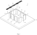
- FIG. 7 is a perspective view of a cell taping apparatus 1 according to an embodiment of the inventive concept.
- the cell taping apparatus 1 includes a plate 12 having a top surface provided with an accommodation space 13 in which a plurality of unit cells 3 of a secondary battery are stacked and accommodated, a guide 11 which extends upward from the top surface of the plate 12 to define the accommodation space 13 therein and through which at least one pair of first slots 111 are lengthily defined to pass downward from an upper end of the guide at positions of both left and right sides, which face each other, respectively, and a tape 14 , which has a length equal to or greater than a width of the plate, of which both ends respectively pass through the pair of first slots 111 , and which is seated on the top surface of the plate so that an adhesion surface 141 faces away from the top surface of the plate.
- the plate 12 has a wide plate shape, and the accommodation space 13 is defined on the top surface of the plate 12 . Also, the plurality of unit cells 3 of the secondary battery are accommodated in the accommodation space 13 .
- Each of the unit cells 3 can be a bi-cell or a mono-cell. Thus, only one of the bi-cell or the mono-cell may be stacked, or more than one of the bi-cell and the mono-cell may be stacked.
- the accommodation space 13 may have a shape and size, which correspond to those of the unit cells 3 .
- the correspondence in shape may mean that the accommodation space 13 has equal or similar to that of the unit cell 3 so that the unit cell 3 is easily accommodated in the accommodation space.
- the correspondence in size may mean that the accommodation space 13 has a size greater than that of the unit cell 3 by an offset value. If the accommodation space 13 has the same size as the unit cell 3 , the unit cell 3 may not be inserted into the accommodation space 13 or may not freely fall by friction with the guide 11 surrounding the accommodation space even though the unit cell 3 is inserted.
- the offset value may be determined experimentally depending on a size and shape of the secondary battery to be manufactured.
- the guide 11 may be disposed on the top surface of the plate 12 to lengthily extend in a direction in which the plurality of unit cells 3 is stacked, thereby defining the accommodation space 13 . That is, the guide 11 may serve as an outer wall of the accommodation space 13 to embody the shape of the accommodation space 13 . Also, when the plurality of unit cells 3 is stacked to form a stack of the unit cells 3 , the guide 11 supports a circumference of the stack of the unit cells 3 .
- At least one pair of first slots 111 are lengthily defined to pass downward from an upper end of the guide 11 at positions of both left and right sides of the guide 11 , which face each other, respectively. Since the tape 14 passes to be inserted into the first slot 111 later, the first slot 111 may have a width corresponding to that of the tape 14 . Here, the correspondence in width may mean that the width is greater than that of the tape 14 by an offset value. If the first slot 111 has the same width as the tape 14 , the tape 14 may not be inserted into the first slot 111 or may be bent even though the tape 14 is inserted.
- the tape 14 may get out of the fixed position and thus be attached to be inclined without being parallel to an edge of one side of the unit cell 3 later.
- the offset value may be determined experimentally depending on the width of the tape 14 to be manufactured.
- the first slot 111 has to be defined at each of positions of both the left and right sides of the guide 11 , which face each other. If the slot is not defined at the positions facing each other, the inserted tape 14 may be attached to be inclined without being parallel to the edge of the one side of the unit cell 3 later.
- the first slot 111 is defined to extend downward from an upper end of the guide 11 . Accordingly, the tape 14 may be easily inserted and also be easily attached to side surfaces of the plurality of unit cells 3 which are inserted into the accommodation space 13 later. Also, since the first slot 111 is defined to pass through the guide 11 , the guide 11 may be divided into a plurality of guides 11 as illustrated in FIG. 7 . Each of the guides 11 may have a polygonal pillar shape and be fixed while defining the accommodation space 13 in the top surface of the plate 12 .
- first slots 111 Although only the pair of first slots 111 are provided, as illustrated in FIG. 7 , a plurality of pairs of slots 111 may be provided.
- the tape 14 may be attached to the plurality of unit cells 3 by the number of pairs of first slots 111 . That is, if one pair of first slots 111 are provided, one tape 14 may be attached to the plurality of unit cells 4 . If three pairs of first slots 111 are provided, three tapes 14 may be attached to the plurality of unit cells 3 .
- the tape 14 has a length equal to or greater than a width of the plate 12 so that both ends of the tape 14 respectively pass through the pair of first slots 111 , and the adhesion surface 141 is seated on the top surface of the plate 12 to face away from the top surface of the plate. Since the tape 14 has a length equal to or greater than the width of the plate 12 , the user may easily hold both ends of the tape 14 later. Also, since both the ends of the tape 14 respectively pass through the first slots facing each other, the tape 14 may be parallel to the edges of one side of the plurality of unit cells 3 .
- the tape 14 is seated on the top surface of the plate 12 while the adhesion surface 141 faces away from the top surface of the plate.
- the tape 14 is seated in the accommodation space 13 defined in the guide 11 on the top surface of the plate 12 .
- the plurality of unit cells 3 is stacked on the top surface of the tape 14 when the tape 14 is seated on the top surface of the plate 12 .
- the tape 14 may be attached to a bottom surface of the plurality of unit cells 3 .
- a cell taping method using the cell taping apparatus 1 according to an embodiment of the present invention includes a step of allowing both ends of a tape 14 to respectively pass through at least one pair of first slots 111 formed in a guide 11 and allowing an adhesion surface 141 of the tape 14 to be seated on a top surface of the plate 12 while facing away from the top surface of the plate, a step of stacking a plurality of unit cells 3 of a secondary battery on a top surface of the tape 14 to accommodate the plurality of unit cells 3 in an accommodation space 13 provided in the top surface of the plate, and a step of allowing both the ends of the tape 14 to move to an upper side of the unit cells 3 so as to adhere to each other.
- both the ends of the tape 14 respectively pass through at least one pair of first slots 111 formed in the guide 11 , and the adhesion surface 141 of the tape 14 is seated on the top surface of the plate 12 while facing away from the top surface of the plate.
- FIG. 8 is a perspective view illustrating a state in which a plurality of unit cells is inserted into the cell taping apparatus according to an embodiment of the present invention.
- the plurality of unit cells 3 of a secondary battery are stacked on a top surface of the tape 14 and accommodated in an accommodation space 13 provided in a top surface of a plate 12 .
- the plurality of unit cells 3 may be inserted and stacked one by one in the accommodation space 13 , but if there is a separate stacking device, a stack itself of the unit cells 3 may be inserted into the accommodation space 13 after being stacked in the separate stacking device.
- the adhesion surface 141 is seated to face away from the top surface of the plate.
- the plurality of unit cells 3 is stacked on the top surface of the tape 14 when the tape 14 is seated on the top surface of the plate 12 .
- the tape 14 may be attached to a lower surface of the plurality of unit cells 3 .
- the electrode tab protrudes outward from one side of the plurality of unit cells 3 .
- the electrode tab includes a positive electrode tab and a negative electrode tab, and the positive electrode tab and the negative electrode tab may protrude in the same direction, but may protrude in different directions.
- the guide 11 is provided with a second slot 112 that is lengthily defined downward from an upper end of the guide 11 at a position corresponding to that at which the electrode tab is disposed on the unit cell 3 .
- the electrode tab may be easily inserted through the second slot 112 .
- the electrode tab is disposed on a surface of the plurality of unit cells 3 , to which the tape 14 is not attached. That is, if the tape 14 is wound from both sides of the plurality of unit cells 3 so as to be attached, the electrode tab is disposed at a front or rear side of the plurality of unit cells 3 .
- the second slot 112 is not defined at both left and right sides of the guide 11 , but preferably defined at the front or the rear sides of the guide 11 .
- FIG. 9 is a perspective view illustrating a state in which the tape 14 of the cell taping apparatus 1 is attached to the side surfaces of the plurality of unit cells according to an embodiment of the present invention.
- both ends of the tape 14 respectively move to an upper side of the unit cells 3 to adhere to each other.
- the tape 14 has a length that is equal to or greater than a width of the plate 12 , the user may easily hold both the ends of the tape 14 to move to the upper side of the plurality of unit cells 3 .
- the tape 14 may naturally pass through the first slot 111 again, and the adhesion surface 141 of the tape 14 may be attached to the side surfaces of the plurality of unit cells 3 .
- the tape 14 may have a straight-line shape without being bent, and thus, the tape 14 may be uniformly attached to the side surfaces of the plurality of unit cells 3 .
- FIG. 10 is a perspective view illustrating a state in which the attachment of the tape is completed according to an embodiment of the present invention
- FIG. 11 is a plan view of FIG. 10
- FIG. 12 is a cross-sectional view of the cell taping apparatus of FIG. 10 , taken along line B-B′.
- the tape 14 is wound around at least once and then attached. Otherwise, adhesion force at both the ends of the tape 14 attached in a degassing process or the like may be reduced, and thus, the tape 14 may be detached.
- both the ends of the tape 14 moving to the upper side of the plurality of unit cells 3 are attached to each other.
- the tape 14 may be attached together not only on the side surfaces of the plurality of unit cells 3 but also on the top surface thereof.
- the tape 14 is wound once around the periphery of the plurality of unit cells 3 . That is, according to an embodiment of the present invention, the tape 14 may be wound at least once around the plurality of stacked unit cells 3 and then attached without repeating the taping operation several times.
- FIG. 13 is a perspective view of a cell taping apparatus 1 a according to another embodiment of the present invention.
- the tape 14 is simply seated on the top surface of the plate 12 .
- the tape 14 may be bent even after the tape 14 is seated on the top surface of the plate 12 . Therefore, when the plurality of unit cells 3 is inserted into the insertion space, the tape 14 may be twisted so that a portion of the non-adhesion surface of the tape 14 contacts the plurality of unit cells 3 , or the adhesion surface 141 may not uniformly adhere.
- a plate 12 a may include a groove 121 that is recessed inward at a position at which both ends of a tape 14 are seated on a top surface.
- a groove 121 that is recessed inward at a position at which both ends of a tape 14 are seated on a top surface.
- FIG. 14 is a perspective view illustrating a state in which the plurality of unit cells 3 is inserted into the cell taping apparatus 1 a according to another embodiment of the present invention.
- the cell taping apparatus 1 a When each of both the ends of the tape 14 is inserted into the groove 121 , the cell taping apparatus 1 a according to another embodiment of the present invention further includes a holder 15 that fixes each of both the ends of the tape 14 to the groove 121 .
- the holder 15 fixes both ends of the tape 14 to the grooves 121 .
- An example of the holder 15 may include tongs that are capable of gripping a specific object with elastic force by using two arms disposed at ends thereof.
- the present invention is not limited thereto, and if both the ends of the tape 14 are fixed to the groove 121 , the holder 15 may be provided in various manners.
- FIG. 15 is a schematic view illustrating a state in which a tape seated in the groove 121 of the cell taping apparatus is fixed by the holder 15 according to another embodiment of the present invention.
- each of both the ends of the tape 14 is inserted into the groove 121 defined in both side ends of the plate 12 a as illustrated in FIG. 14 . Also, the holder 15 fixes the tape 14 to the groove 121 . As a result, the tape 14 may be seated on the plate 12 a and then fixed. Therefore, the tape 14 may be prevented from being bent or twisted so that the tape 14 is uniformly attached to a lower surface of the plurality of unit cells 3 .
Landscapes
- Chemical & Material Sciences (AREA)
- Chemical Kinetics & Catalysis (AREA)
- Electrochemistry (AREA)
- General Chemical & Material Sciences (AREA)
- Engineering & Computer Science (AREA)
- Manufacturing & Machinery (AREA)
- Life Sciences & Earth Sciences (AREA)
- Sustainable Development (AREA)
- Sustainable Energy (AREA)
- Battery Mounting, Suspending (AREA)
Abstract
Description
Claims (18)
Applications Claiming Priority (2)
| Application Number | Priority Date | Filing Date | Title |
|---|---|---|---|
| KR10-2018-0135170 | 2018-11-06 | ||
| KR1020180135170A KR102741418B1 (en) | 2018-11-06 | 2018-11-06 | The Apparatus For Taping Cell And The Method For Taping Cell |
Publications (2)
| Publication Number | Publication Date |
|---|---|
| US20200144650A1 US20200144650A1 (en) | 2020-05-07 |
| US11217812B2 true US11217812B2 (en) | 2022-01-04 |
Family
ID=70459173
Family Applications (1)
| Application Number | Title | Priority Date | Filing Date |
|---|---|---|---|
| US16/672,907 Active 2040-04-08 US11217812B2 (en) | 2018-11-06 | 2019-11-04 | Cell taping apparatus and method |
Country Status (2)
| Country | Link |
|---|---|
| US (1) | US11217812B2 (en) |
| KR (1) | KR102741418B1 (en) |
Families Citing this family (4)
| Publication number | Priority date | Publication date | Assignee | Title |
|---|---|---|---|---|
| KR102911278B1 (en) * | 2020-10-19 | 2026-01-13 | 주식회사 엘지에너지솔루션 | Electrode assembly |
| JP7208209B2 (en) | 2020-11-09 | 2023-01-18 | プライムプラネットエナジー&ソリューションズ株式会社 | battery |
| KR20230109986A (en) | 2022-01-14 | 2023-07-21 | 주식회사 엘지에너지솔루션 | Taping apparatus of stack cell |
| US20250293287A1 (en) * | 2024-03-12 | 2025-09-18 | Lg Energy Solution, Ltd. | Electrode stacking device for battery cell assembly |
Citations (2)
| Publication number | Priority date | Publication date | Assignee | Title |
|---|---|---|---|---|
| WO2015065082A1 (en) * | 2013-10-31 | 2015-05-07 | 주식회사 엘지화학 | Battery cell stacking jig |
| KR20150049768A (en) | 2013-10-31 | 2015-05-08 | 주식회사 엘지화학 | Device for Taping Electrode Assembly of Battery Cell and Battery Cell Manufactured Using the same |
Family Cites Families (5)
| Publication number | Priority date | Publication date | Assignee | Title |
|---|---|---|---|---|
| KR101596092B1 (en) | 2013-07-03 | 2016-02-19 | 주식회사 엘지화학 | Liquid composition for doping alkali metal, cis based solar cell and its manufacturing method using the same |
| KR101888208B1 (en) * | 2013-10-31 | 2018-08-14 | 주식회사 엘지화학 | Zig for stacking battery cell |
| JP6207072B2 (en) * | 2013-11-25 | 2017-10-04 | ハイメカ株式会社 | Electronic component taping equipment |
| KR101787165B1 (en) * | 2014-06-10 | 2017-10-18 | 주식회사 엘지화학 | Jig device for battery cell |
| KR102087751B1 (en) * | 2016-03-25 | 2020-03-12 | 주식회사 엘지화학 | System for manufacturing an electrode assembly |
-
2018
- 2018-11-06 KR KR1020180135170A patent/KR102741418B1/en active Active
-
2019
- 2019-11-04 US US16/672,907 patent/US11217812B2/en active Active
Patent Citations (2)
| Publication number | Priority date | Publication date | Assignee | Title |
|---|---|---|---|---|
| WO2015065082A1 (en) * | 2013-10-31 | 2015-05-07 | 주식회사 엘지화학 | Battery cell stacking jig |
| KR20150049768A (en) | 2013-10-31 | 2015-05-08 | 주식회사 엘지화학 | Device for Taping Electrode Assembly of Battery Cell and Battery Cell Manufactured Using the same |
Also Published As
| Publication number | Publication date |
|---|---|
| KR102741418B1 (en) | 2024-12-12 |
| KR20200052060A (en) | 2020-05-14 |
| US20200144650A1 (en) | 2020-05-07 |
Similar Documents
| Publication | Publication Date | Title |
|---|---|---|
| US11217812B2 (en) | Cell taping apparatus and method | |
| ES2985092T3 (en) | Apparatus and method of notching for secondary battery | |
| KR102414044B1 (en) | Tapping device and taping method for adhesive tape that can be attached to battery cells | |
| US20200368855A1 (en) | Pressurization jig for pressurizing busbar and battery module manufacturing system comprising same | |
| EP3346520A1 (en) | Battery cell and method for manufacturing same | |
| CN104969399B (en) | Battery Cell Stacking Fixture | |
| CN101689625B (en) | battery structure | |
| JP3794261B2 (en) | Method and apparatus for winding spiral electrode group and battery using the same | |
| US20200259157A1 (en) | Battery Pack | |
| EP3514876B1 (en) | Electrode assembly and method for manufacturing same | |
| JP2003178792A (en) | Secondary battery | |
| KR101628892B1 (en) | Secondary battery having stepped cell structure | |
| US20180316050A1 (en) | Secondary battery and current collector terminal | |
| EP4203151A1 (en) | Apparatus and method for checking for mis-assembly of battery cell activation tray or twisting thereof during operation | |
| EP4040553A1 (en) | Electrode assembly and manufacturing method therefor | |
| KR20210023527A (en) | Secondary battery and method for manufacturing the same | |
| US20150263317A1 (en) | Secondary battery pack | |
| JP6464820B2 (en) | Method for manufacturing power storage device | |
| US20190260089A1 (en) | Lithium secondary battery including cylindrical jelly roll | |
| KR20200032996A (en) | A pressing jig for pressing a bus bar and a battery module manufacturing system comprising the same | |
| KR102534990B1 (en) | Winding device | |
| EP4024546A1 (en) | Electrode assembly and method for manufacturing same | |
| US11411288B2 (en) | Battery pack | |
| EP3753716A1 (en) | Apparatus for applying adhesive and method for applying adhesive | |
| KR102197998B1 (en) | Rolling device for secondary battery |
Legal Events
| Date | Code | Title | Description |
|---|---|---|---|
| FEPP | Fee payment procedure |
Free format text: ENTITY STATUS SET TO UNDISCOUNTED (ORIGINAL EVENT CODE: BIG.); ENTITY STATUS OF PATENT OWNER: LARGE ENTITY |
|
| STPP | Information on status: patent application and granting procedure in general |
Free format text: DOCKETED NEW CASE - READY FOR EXAMINATION |
|
| AS | Assignment |
Owner name: LG CHEM, LTD., KOREA, REPUBLIC OF Free format text: ASSIGNMENT OF ASSIGNORS INTEREST;ASSIGNORS:KIM, HYE JIN;BAE, SUNG HOON;CHUNG, DAE SIK;REEL/FRAME:056300/0556 Effective date: 20210420 |
|
| STPP | Information on status: patent application and granting procedure in general |
Free format text: NON FINAL ACTION MAILED |
|
| STPP | Information on status: patent application and granting procedure in general |
Free format text: RESPONSE TO NON-FINAL OFFICE ACTION ENTERED AND FORWARDED TO EXAMINER |
|
| STPP | Information on status: patent application and granting procedure in general |
Free format text: NOTICE OF ALLOWANCE MAILED -- APPLICATION RECEIVED IN OFFICE OF PUBLICATIONS |
|
| AS | Assignment |
Owner name: LG ENERGY SOLUTION, LTD., KOREA, REPUBLIC OF Free format text: ASSIGNMENT OF ASSIGNORS INTEREST;ASSIGNOR:LG CHEM, LTD.;REEL/FRAME:058295/0068 Effective date: 20211027 |
|
| STPP | Information on status: patent application and granting procedure in general |
Free format text: PUBLICATIONS -- ISSUE FEE PAYMENT VERIFIED |
|
| STCF | Information on status: patent grant |
Free format text: PATENTED CASE |
|
| MAFP | Maintenance fee payment |
Free format text: PAYMENT OF MAINTENANCE FEE, 4TH YEAR, LARGE ENTITY (ORIGINAL EVENT CODE: M1551); ENTITY STATUS OF PATENT OWNER: LARGE ENTITY Year of fee payment: 4 |