US11216229B2 - Information processing apparatus, non-transitory computer readable medium storing program, and management system - Google Patents
Information processing apparatus, non-transitory computer readable medium storing program, and management system Download PDFInfo
- Publication number
- US11216229B2 US11216229B2 US16/168,854 US201816168854A US11216229B2 US 11216229 B2 US11216229 B2 US 11216229B2 US 201816168854 A US201816168854 A US 201816168854A US 11216229 B2 US11216229 B2 US 11216229B2
- Authority
- US
- United States
- Prior art keywords
- processing
- user
- processing device
- delayed
- case
- Prior art date
- Legal status (The legal status is an assumption and is not a legal conclusion. Google has not performed a legal analysis and makes no representation as to the accuracy of the status listed.)
- Active, expires
Links
Images


Classifications
-
- H—ELECTRICITY
- H04—ELECTRIC COMMUNICATION TECHNIQUE
- H04N—PICTORIAL COMMUNICATION, e.g. TELEVISION
- H04N1/00—Scanning, transmission or reproduction of documents or the like, e.g. facsimile transmission; Details thereof
- H04N1/00127—Connection or combination of a still picture apparatus with another apparatus, e.g. for storage, processing or transmission of still picture signals or of information associated with a still picture
- H04N1/00344—Connection or combination of a still picture apparatus with another apparatus, e.g. for storage, processing or transmission of still picture signals or of information associated with a still picture with a management, maintenance, service or repair apparatus
-
- G—PHYSICS
- G06—COMPUTING; CALCULATING OR COUNTING
- G06F—ELECTRIC DIGITAL DATA PROCESSING
- G06F3/00—Input arrangements for transferring data to be processed into a form capable of being handled by the computer; Output arrangements for transferring data from processing unit to output unit, e.g. interface arrangements
- G06F3/12—Digital output to print unit, e.g. line printer, chain printer
- G06F3/1201—Dedicated interfaces to print systems
- G06F3/1223—Dedicated interfaces to print systems specifically adapted to use a particular technique
- G06F3/1237—Print job management
- G06F3/126—Job scheduling, e.g. queuing, determine appropriate device
- G06F3/1261—Job scheduling, e.g. queuing, determine appropriate device by using alternate printing
-
- G—PHYSICS
- G06—COMPUTING; CALCULATING OR COUNTING
- G06F—ELECTRIC DIGITAL DATA PROCESSING
- G06F3/00—Input arrangements for transferring data to be processed into a form capable of being handled by the computer; Output arrangements for transferring data from processing unit to output unit, e.g. interface arrangements
- G06F3/12—Digital output to print unit, e.g. line printer, chain printer
- G06F3/1201—Dedicated interfaces to print systems
- G06F3/1202—Dedicated interfaces to print systems specifically adapted to achieve a particular effect
- G06F3/1211—Improving printing performance
- G06F3/1212—Improving printing performance achieving reduced delay between job submission and print start
-
- G—PHYSICS
- G06—COMPUTING; CALCULATING OR COUNTING
- G06F—ELECTRIC DIGITAL DATA PROCESSING
- G06F3/00—Input arrangements for transferring data to be processed into a form capable of being handled by the computer; Output arrangements for transferring data from processing unit to output unit, e.g. interface arrangements
- G06F3/12—Digital output to print unit, e.g. line printer, chain printer
- G06F3/1201—Dedicated interfaces to print systems
- G06F3/1223—Dedicated interfaces to print systems specifically adapted to use a particular technique
- G06F3/1237—Print job management
- G06F3/1238—Secure printing, e.g. user identification, user rights for device usage, unallowed content, blanking portions or fields of a page, releasing held jobs
-
- G—PHYSICS
- G06—COMPUTING; CALCULATING OR COUNTING
- G06F—ELECTRIC DIGITAL DATA PROCESSING
- G06F3/00—Input arrangements for transferring data to be processed into a form capable of being handled by the computer; Output arrangements for transferring data from processing unit to output unit, e.g. interface arrangements
- G06F3/12—Digital output to print unit, e.g. line printer, chain printer
- G06F3/1201—Dedicated interfaces to print systems
- G06F3/1223—Dedicated interfaces to print systems specifically adapted to use a particular technique
- G06F3/1237—Print job management
- G06F3/1253—Configuration of print job parameters, e.g. using UI at the client
- G06F3/1255—Settings incompatibility, e.g. constraints, user requirements vs. device capabilities
-
- G—PHYSICS
- G06—COMPUTING; CALCULATING OR COUNTING
- G06F—ELECTRIC DIGITAL DATA PROCESSING
- G06F3/00—Input arrangements for transferring data to be processed into a form capable of being handled by the computer; Output arrangements for transferring data from processing unit to output unit, e.g. interface arrangements
- G06F3/12—Digital output to print unit, e.g. line printer, chain printer
- G06F3/1201—Dedicated interfaces to print systems
- G06F3/1223—Dedicated interfaces to print systems specifically adapted to use a particular technique
- G06F3/1237—Print job management
- G06F3/1268—Job submission, e.g. submitting print job order or request not the print data itself
-
- G—PHYSICS
- G06—COMPUTING; CALCULATING OR COUNTING
- G06F—ELECTRIC DIGITAL DATA PROCESSING
- G06F3/00—Input arrangements for transferring data to be processed into a form capable of being handled by the computer; Output arrangements for transferring data from processing unit to output unit, e.g. interface arrangements
- G06F3/12—Digital output to print unit, e.g. line printer, chain printer
- G06F3/1201—Dedicated interfaces to print systems
- G06F3/1223—Dedicated interfaces to print systems specifically adapted to use a particular technique
- G06F3/1237—Print job management
- G06F3/1273—Print job history, e.g. logging, accounting, tracking
-
- G—PHYSICS
- G06—COMPUTING; CALCULATING OR COUNTING
- G06F—ELECTRIC DIGITAL DATA PROCESSING
- G06F3/00—Input arrangements for transferring data to be processed into a form capable of being handled by the computer; Output arrangements for transferring data from processing unit to output unit, e.g. interface arrangements
- G06F3/12—Digital output to print unit, e.g. line printer, chain printer
- G06F3/1201—Dedicated interfaces to print systems
- G06F3/1278—Dedicated interfaces to print systems specifically adapted to adopt a particular infrastructure
- G06F3/1285—Remote printer device, e.g. being remote from client or server
-
- G—PHYSICS
- G06—COMPUTING; CALCULATING OR COUNTING
- G06F—ELECTRIC DIGITAL DATA PROCESSING
- G06F9/00—Arrangements for program control, e.g. control units
- G06F9/06—Arrangements for program control, e.g. control units using stored programs, i.e. using an internal store of processing equipment to receive or retain programs
- G06F9/46—Multiprogramming arrangements
- G06F9/54—Interprogram communication
- G06F9/542—Event management; Broadcasting; Multicasting; Notifications
-
- G—PHYSICS
- G06—COMPUTING; CALCULATING OR COUNTING
- G06F—ELECTRIC DIGITAL DATA PROCESSING
- G06F3/00—Input arrangements for transferring data to be processed into a form capable of being handled by the computer; Output arrangements for transferring data from processing unit to output unit, e.g. interface arrangements
- G06F3/12—Digital output to print unit, e.g. line printer, chain printer
- G06F3/1201—Dedicated interfaces to print systems
- G06F3/1202—Dedicated interfaces to print systems specifically adapted to achieve a particular effect
- G06F3/1203—Improving or facilitating administration, e.g. print management
- G06F3/1204—Improving or facilitating administration, e.g. print management resulting in reduced user or operator actions, e.g. presetting, automatic actions, using hardware token storing data
-
- G—PHYSICS
- G06—COMPUTING; CALCULATING OR COUNTING
- G06F—ELECTRIC DIGITAL DATA PROCESSING
- G06F3/00—Input arrangements for transferring data to be processed into a form capable of being handled by the computer; Output arrangements for transferring data from processing unit to output unit, e.g. interface arrangements
- G06F3/12—Digital output to print unit, e.g. line printer, chain printer
- G06F3/1201—Dedicated interfaces to print systems
- G06F3/1202—Dedicated interfaces to print systems specifically adapted to achieve a particular effect
- G06F3/1222—Increasing security of the print job
-
- G—PHYSICS
- G06—COMPUTING; CALCULATING OR COUNTING
- G06F—ELECTRIC DIGITAL DATA PROCESSING
- G06F3/00—Input arrangements for transferring data to be processed into a form capable of being handled by the computer; Output arrangements for transferring data from processing unit to output unit, e.g. interface arrangements
- G06F3/12—Digital output to print unit, e.g. line printer, chain printer
- G06F3/1201—Dedicated interfaces to print systems
- G06F3/1223—Dedicated interfaces to print systems specifically adapted to use a particular technique
- G06F3/1237—Print job management
- G06F3/1267—Job repository, e.g. non-scheduled jobs, delay printing
Definitions
- the present invention relates to an information processing apparatus, a non-transitory computer readable medium storing a program, and a management system.
- an information processing apparatus which includes an extraction section that extracts delayed processing having a waiting time which is longer than a predetermined time, from a use history of each of plural users using plural processing devices, the waiting time being a time from performing of an instruction to perform processing to starting of performing the processing, an analysis section that analyzes a cause of the delayed processing, and a notification section that notifies the user who has performed an instruction to perform the delayed processing, of at least one of an analysis result obtained by the analysis section or a countermeasure based on the analysis result.
- FIG. 1 is a block diagram illustrating an example of a configuration of a management system
- FIG. 2 is a block diagram illustrating an example of an electrical configuration of a management server
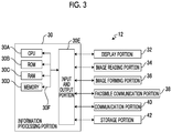
- FIG. 3 is a block diagram illustrating an example of an electrical configuration of a processing device
- FIG. 4 is a plan view illustrating an arrangement example of the processing device and a user
- FIG. 5 is a time chart illustrating an example of a relationship between a processing step and a use history of accumulation printing in time series;
- FIG. 6 is a time chart illustrating an example of a relationship between a processing step and a use history of normal printing in time series
- FIG. 7 is a flowchart illustrating an example of a processing flow of “an efficiency improvement processing program”
- FIG. 8 is a flowchart illustrating an example of a flow of “delay extraction processing”
- FIG. 9 is a diagram illustrating an example of a delayed processing list
- FIG. 10 is a flowchart illustrating an example of a flow of “cause analysis processing”
- FIG. 11 is a flowchart illustrating an example of a flow of “notification processing”
- FIG. 12 is a table illustrating an example of information regarding a function of each of plural processing devices
- FIG. 13 is a table illustrating an example of pieces of authority information of plural users for each of the plural processing devices
- FIG. 14 is a diagram illustrating an example of a processing concentration list
- FIG. 15 is a table illustrating an example of information regarding a required time to each of the plural processing devices
- FIG. 16 is a plan view illustrating a path from a user A to each of the processing devices
- FIG. 17 is a diagram illustrating an example of an inconvenient use list
- FIG. 18 is a graph illustrating a use ratio of each function in the entirety of the system.
- FIG. 19 is a graph illustrating a latency time of each function for each time zone.
- FIG. 20 is a graph illustrating a use ratio of each function for each device.
- FIG. 1 is a block diagram illustrating an example of a configuration of the management system.
- the management system includes a management server 10 , plural processing devices 12 managed by the management server 10 , plural terminal devices 14 which are respectively used by plural users, and a storage device 16 disposed on the outside of the management server 10 .
- the management server 10 , the plural processing devices 12 , the plural terminal devices 14 , and the storage device 16 are connected to a communication line 18 so as to transmit and receive information to and from each other via the communication line 18 .
- the management server 10 is an example of “an information processing apparatus”.
- a user requests the plural processing devices 12 to perform processing, via the terminal device 14 used by the user.
- Each of the plural processing devices 12 performs the requested processing and records a use history for each piece of processing.
- the recorded use history is held in a storage device of each of the processing devices and is also copied to the storage device 16 .
- the management server 10 manages processing states of the plural processing devices 12 such that pieces of processing are efficiently performed in the entirety of the system.
- the management server 10 acquires use histories of the plural processing devices from the storage device 16 and extracts delayed processing having a waiting time longer than that in a normal case.
- the management server 10 analyzes the cause of processing being delayed, for each extracted delayed processing.
- the management server 10 notifies the user of at least one of an analysis result or a countermeasure.
- the management server 10 notifies a manager of an inefficient use situation, for example, uses which are concentrated on a specific processing device or an inconvenient use of a specific user.
- FIG. 2 is a block diagram illustrating an example of an electrical configuration of the management server.
- the management server 10 includes an information processing portion 20 .
- the information processing portion 20 is configured as a computer that controls the entirety of the server and performs various operations. That is, the information processing portion 20 includes a central processing unit (CPU) 20 A, a read only memory (ROM) 20 B, a random access memory (RAM) 20 C, a nonvolatile memory 20 D, and an input and output portion (I/O) 20 E.
- CPU central processing unit
- ROM read only memory
- RAM random access memory
- I/O input and output portion
- the CPU 20 A, the ROM 20 B, the RAM 20 C, the memory 20 D, and the I/O 20 E are connected to each other via a bus 20 F.
- the CPU 20 A reads a program stored in the ROM 20 B and executes the program by using the RAM 20 C as a work area.
- a display portion 22 such as a display, an input portion 24 such as a keyboard or a mouse, a communication portion 26 , and a storage portion 28 are connected to the I/O 20 E of the information processing portion 20 .
- the communication portion 26 is an interface for communicating with an external device via a wired or wireless communication line.
- the communication portion functions as an interface for communicating with the external device such as a computer, which is connected to a network such as a local area network (LAN) or the Internet.
- the storage portion 28 is an external storage device such as a hard disk.
- a storage area of the program is not limited to the ROM 20 B.
- the various programs may be stored in other storage devices such as the memory 20 D or the storage portion 28 and may be acquired from the external device via the communication portion 26 .
- Various drives may be connected to the information processing portion 20 .
- the various drives are devices that read data from a computer-readable portable recording medium such as a CD-ROM and a universal serial bus (USB) memory or write data in the recording medium.
- the program may be recorded in a portable recording medium and may be read and executed by the drive corresponding to the recording medium.
- the electrical configuration of the terminal device is the same as that of the management server, and thus descriptions thereof will not be repeated.
- the processing device is a device that performs processing in accordance with an instruction from a user.
- the processing device is a multifunctional device having various functions, for example, as follows: a printing function of forming an image corresponding to image data on paper; a scanner function of reading an image formed on paper, as image data; a facsimile function of transmitting image data to another image processing device connected to a public line or the like; and a copying function of copying an image formed on paper, to another piece of paper.
- FIG. 3 is a block diagram illustrating an example of an electrical configuration of the processing device.
- the processing device 12 includes an information processing portion 30 .
- the information processing portion 30 is configured as a computer that controls the entirety of the server and performs various operations. That is, the information processing portion 30 includes a CPU 30 A, a ROM 30 B, a RAM 30 C, a memory 30 D, and an I/O 30 E.
- the CPU 30 A, the ROM 30 B, the RAM 30 C, the memory 30 D, and the I/O 30 E are connected to each other via a bus 30 F.
- the CPU 30 A reads a program stored in the ROM 30 B and executes the program by using the RAM 30 C as a work area.
- the processing device 12 is a multifunctional device having plural functions.
- An operation display portion 32 , an image reading portion 34 , an image forming portion 36 , a facsimile communication portion 38 , a communication portion 40 , and a storage portion 42 are connected to the I/O 30 E of the information processing portion 30 .
- the operation display portion 32 includes various buttons, an operation panel for displaying various screens, and the like. With the configuration, the operation display portion 32 receives an operation from a user and displays various kinds of information for the user.
- the image reading portion 34 includes an image reader such as a line sensor. With the configuration, the image reading portion 34 reads an image recorded on an original document and outputs image data obtained by reading the image to the CPU 30 A via the I/O 30 E.
- the image forming portion 36 forms an image on paper based on image data.
- An image forming method may be an electrophotographic method or an ink jet method.
- the image forming portion 36 includes an image forming unit, a fixing device, and the like.
- the image forming unit includes a photosensitive drum, a charging device, an exposure device, a developing device, a transferring device, a cleaning device, and the like.
- the facsimile communication portion 38 transmits and receives a facsimile message.
- the communication portion 40 is an interface for communicating with an external device via a wired or wireless communication line.
- the storage portion 42 is an external storage device such as a hard disk.
- the facsimile function is abbreviated as “the FAX function”.
- FIG. 4 is a plan view illustrating an arrangement example of processing devices and users. As illustrated in FIG. 4 , in an area illustrated, there are four users A, B, C, and D and four processing devices 12 N, 12 W, 12 E, and 12 S are disposed. In the area illustrated, four terminal devices used by the users A, B, C, and D are arranged. The four processing devices 12 are distinguished from each other by using letters representing cardinal directions. In a case where distinguishment of the processing devices from each other is not required, the processing devices are collectively referred to as the processing device 12 .
- the processing device 12 N is a multifunctional device which does not have a color printing function and the FAX function and is disposed on the north side of the area.
- the processing device 12 W is a multifunctional device which includes the color printing function but does not include the FAX function.
- the processing device 12 W is disposed on the west side of the area.
- the processing device 12 E is a multifunctional device which includes the color printing function and the FAX function and is disposed on the east side of the area.
- the processing device 12 S is a multifunctional device which does not have a color printing function and the FAX function and is disposed on the south side of the area.
- the seat of the user A is close to the processing device 12 W on the west side of the south.
- the seat of the user B is close to the processing device 12 E on the east side of the north.
- the seat of the user C is close to the processing device 12 W on the west side of the north.
- the seat of the user D is close to the processing device 12 E on the east side of the south.
- the seats of the users are separated from each other by partitions, and passages are formed along the partitions.
- the user performs color printing with the processing device 12 E on the east side five times and performs black-and-white printing with the processing device 12 W on the west side one time per day.
- the color printing may also be performed by the processing device 12 W which is on the west side and is close to the seat of the user A.
- the user A does not perform the color printing with the processing device 12 W on the west side.
- This case is considered as an inefficient use situation of the user A, from various viewpoints.
- this case is considered as “an inconvenient use” in which a frequency of using the processing device 12 E which is on the east side and is far from the user A is high and a moving time is long.
- this case is considered as “a mismatched use”, for example, in which black-and-white printing is performed with the processing device 12 W which includes the color printing function and is on the west side.
- a concentrated use occurs in the processing device 12 E on the east side. Because of “the mismatched use” or “the concentrated use”, pieces of processing may be concentrated on the specific processing device 12 and a processing time may increase.
- such an inefficient use situation is extracted from the use history of each of the plural processing devices 12 , as “delayed processing” which will be described later.
- the cause of delay is analyzed for each piece of “the delayed processing” and the user is notified of at least one of the analysis result or the countermeasure. For example, in the above case, the user A is informed that color printing may be also performed by the processing device 12 W on the west side. The specific procedures will be described later.
- each of the plural processing devices 12 performs processing in response to a request from a user.
- Each of the plural processing devices 12 records plural steps from performing of an instruction to perform processing to an end of the processing and leaves the recorded steps as a use history.
- FIG. 5 is a time chart illustrating an example of a relationship between the processing step and the use history of accumulation printing in time series.
- the accumulation printing is printing processing using an accumulation function.
- “accumulation printing” is designated in print data
- printing processing is not performed and print data is stored in the storage portion (not illustrated), until a user is authenticated by the processing device.
- printing processing is started.
- a user transmits print data to the processing device 12 from the terminal device 14 and instructs the processing device 12 to perform processing. Then, the user goes to a place in which the processing device 12 is disposed and performs an authentication procedure, for example, presenting identification information (ID) or a password. After the authentication procedure, performing the processing as a target of the instruction from the processing device 12 is started. Then, the processing is ended. Finally, the user collects a printed matter from the processing device 12 and goes back to the own seat.
- ID identification information
- a reception time point t 0 of print data, an authentication acceptance time point t 1 , a processing start time point t 2 , and a processing end time point t 3 are recorded as the use history, in addition to “user name” of the user A or the like and “function to be used” such as color printing, black-and-white printing, and FAX transmission.
- a face authentication camera is mounted in the processing device, a time point at which the face of the user has been recognized is also recorded as the use history.
- a time from performing of an instruction to perform processing to an end of the processing is defined as “a waiting time”. It is determined whether or not an instruction to perform processing is performed, based on determination of whether or not the processing device recognizes the instruction. For example, in the printing processing, it is recognized that an instruction to perform processing has been performed, by the processing device receiving print data.
- the processing time is a time from starting of performing processing (in the following descriptions, simply referred to as “start of processing”) to end of the processing.
- the processing time is determined in accordance with a load of processing, for example, a seconds in a case of one page and 100 a seconds in a case of 100 pages.
- the processing time for one page is determined in accordance with the function to be used, such as black-and-white printing, color printing, and FAX transmission.
- the waiting time increases due to various circumstances.
- a time to perform the authentication procedure becomes long.
- a time to perform the authentication procedure becomes delayed.
- FIG. 6 is a time chart illustrating an example of a relationship between a processing step and a use history of normal printing in time series.
- normal printing in a case where print data is received, performing printing processing is started.
- a user transmits print data to the processing device 12 from the terminal device 14 and instructs the processing device 12 to perform processing. After an instruction to perform the processing has been performed, the processing requested by the processing device 12 is started and then ends. Finally, the user collects a printed matter from the processing device 12 and comes back to the seat.
- a reception time point t 0 of print data, a processing start time point t 2 , and a processing end time point t 3 are recorded as the use history, in addition to the user name of the user and the function to be used.
- the “waiting time” from performing of an instruction to perform processing to starting of performing the processing also increases by various circumstances. For example, similar to accumulation printing, in a case where the user is required to wait because another user is using the processing device 12 , a time to start the processing becomes long.
- FIG. 7 is a flowchart illustrating an example of a flow of processing of “the efficiency improvement processing program”.
- “An information transmission processing program” is stored in the ROM 20 B of the management server 10 .
- “the efficiency improvement processing program” is read from the ROM 20 B and executed by the CPU 20 A of the management server 10 .
- Step 100 use histories of the plural processing devices are acquired from the storage device 16 .
- the use history in a predetermined range such as a period of one hour, one day, or one week is acquired in accordance with the purpose. For example, in a case where an environment in which plural processing devices are used by plural users corresponds to an office, the use history for a time zone such as a starting time and a closing time, in which the processing device is highly required, may be acquired.
- Step 102 “delay extraction processing” as an example of extraction means is performed.
- delay extraction processing processing having a waiting time longer than that in a normal case is extracted.
- the waiting time required for the processing is compared to a threshold and processing having a waiting time which is equal to or greater than the threshold is referred to as “the delayed processing”.
- Step 104 “cause analysis processing” as an example of analysis means is performed.
- the cause analysis processing the cause of processing being delayed is analyzed for each extracted piece of delayed processing.
- Step 106 “notification processing” is performed and then the routine is ended.
- the notification processing the user is notified of at least one of the analysis result or the countermeasure and the manager is notified of an occurrence of an inefficient use situation.
- the CPU 20 A that performs “the delay extraction processing” corresponds to an example of “the extraction section”.
- the CPU 2 OA that performs “the cause analysis processing” corresponds to an example of “the analysis section”.
- the CPU 20 A that performs the notification processing corresponds to an example of “a notification section”.
- FIG. 8 is a flowchart illustrating an example of a flow of the delay extraction processing.
- use histories of plural processing devices, which are generated by plural users are acquired, respectively.
- the use history for each piece of processing is referred to as “a processing history”.
- Step 200 one processing history is selected.
- Use histories are organized so as to be allowed to be searched.
- the processing histories of the processing devices may be selected in order of the processing devices 12 N ⁇ 12 W ⁇ 12 E ⁇ 12 S.
- the processing histories for the users may be selected in order of, for example, the users A ⁇ B ⁇ C ⁇ D.
- the processing history of each user is selected in order of the users A ⁇ B ⁇ C ⁇ D.
- Step 202 it is determined whether or not the waiting time is equal to or longer than the threshold (predetermined time).
- the threshold predetermined time.
- the waiting time may include the moving time in accordance with the function to be used, a time such as “XX seconds” is predetermined as the threshold.
- the threshold may be determined qualitatively from the sense of the user, for example, the user may set a time at which the user feels “the processing is slow” as the threshold.
- the threshold may be determined based on the use history, for example, the threshold may be set to be a value based on the representative value of the waiting time obtained from the use histories.
- the representative value includes the maximum value, the minimum value, an average value, a median value, a mode value, and the like. For example, the threshold is set to be a time longer than the average value by YY seconds.
- Step 204 processing having a waiting time which is equal to or greater than the threshold is referred to as “the delayed processing”.
- the process proceeds to Step 204 .
- a processing history of the processing determined to be the delayed processing is added to “a delayed processing list”.
- Step 204 is skipped, and the process proceeds to Step 206 .
- Step 206 it is determined whether or not another processing history is provided. In a case where another processing history is not provided, the routine is ended. In a case where another processing history is provided, the process returns to Step 200 and the procedure from Step 200 to Step 206 is repeated until it is determined whether or not each of pieces of processing for all processing histories is the delayed processing.
- FIG. 9 is a diagram illustrating an example of the delayed processing list. As illustrated in FIG. 9 , four pieces of delayed processing are provided for the user A and two pieces of delayed processing are provided for each of the users B, C, and D. The delayed processing is numbered in order of being added to the list, for example, Processing 1 and Processing 2.
- Processing 1 is added as the delayed processing because the waiting time is 70 seconds, long when the user A uses the color printing function of the processing device 12 E at 9 o'clock.
- the threshold is set to 30 seconds regardless of the type of the function such as color printing or FAX transmission and processing having a waiting time which is equal to or greater than 30 seconds is set to be “the delayed processing”.
- the waiting time includes “a latency time” and “a moving time”. “The latency time” is generated by processing being concentrated on a specific processing device. “The moving time” becomes longer as a distance from a user to the processing device is increased. Separating “the latency time” and “the moving time” from each other is difficult, but the cause of delay is specified.
- FIG. 10 is a flowchart illustrating an example of a flow of “the cause analysis processing”.
- Step 300 one piece of delayed processing is selected.
- delayed processing may be selected in an ascending order from Processing 1 (see FIG. 9 ).
- Step 302 it is determined whether or not plural pieces of processing which are the same as processing related to the selected delayed processing are delayed. In a case where plural pieces of delayed processing are the same as each other, the process proceeds to Step 304 .
- Step 310 it is analyzed that the cause of delay is the long moving time.
- Step 304 it is determined whether or not processing which is the same as processing (device and function) relating to the selected delayed processing is delayed for plural users. In a case where the processing is delayed for the plural users, the process proceeds to Step 306 . In Step 306 , it is analyzed that the cause of delay is the long latency time.
- Step 310 it is analyzed that the cause of delay is the long moving time. A case where delay occurs by one user simultaneously requesting plural pieces of processing is not assumed to be considered. The user can predict delay of processing.
- Step 308 it is determined whether or not another piece of delayed processing is provided. In a case where another delayed processing is not provided, the routine is ended. In a case where another piece of delayed processing is provided, the process returns to Step 300 and the procedure from Step 300 to Step 310 is repeated until the causes for all pieces of delayed processing are specified.
- Processing 1 and Processing 2 are pieces of processing for normal printing, which use the color printing function of the processing device 12 E.
- An instruction to perform Processing 1 and Processing 2 is performed by the user A.
- An instruction to perform Processing 6 is performed by the user B.
- An instruction to perform Processing 7 is performed by the user C.
- An instruction to perform Processing 10 is performed by the user D.
- the processing device 12 E is instructed to perform each of Processing 1, Processing 2, Processing 6, Processing 7, and Processing 10 around 9 o'clock. An instruction to perform the pieces of processing is performed in order of Processing 1 ⁇ Processing 6 ⁇ Processing 7 ⁇ Processing 10 ⁇ Processing 2.
- the processing device 12 E starts processing in order of receiving an instruction to perform the processing. However, in a case where processing as a target of an instruction which has been previously received does not end, the next processing is not started.
- the processing using the color printing function is concentrated on the processing device 12 E and thus the latency time of the user becomes longer in a staggering manner and plural pieces of delayed processing are generated.
- the moving time is not included in the use history. It is assumed that the waiting time of the Processing 1 is 70 seconds, that is, long, but a time is taken to start the processing device 12 or return from a sleep mode in the Processing 1.
- Processing 4, Processing 5, Processing 8, and Processing 9 are pieces of processing using the FAX function of the processing device 12 E.
- An instruction to perform Processing 4 is performed by the user A.
- An instruction to perform Processing 5 is performed by the user B.
- An instruction to perform Processing 8 is performed by the user C.
- An instruction to perform Processing 9 is performed by the user D.
- the processing device 12 E is instructed to perform each of Processing 4, Processing 5, Processing 8, and Processing 9 around 9:30.
- An instruction to perform the pieces of processing is performed in order of Processing 9 ⁇ Processing 8 ⁇ Processing 5 ⁇ Processing 4.
- the processing device 12 E starts processing in order of receiving an instruction to perform the processing. However, in a case where processing as a target of an instruction which has been previously received does not end, the next processing is not started. In this example, the processing using the FAX function is concentrated on the processing device 12 E and thus plural pieces of delayed processing are generated.
- Processing 3 is processing for accumulation printing, which uses the color printing function of the processing device 12 E.
- An instruction to perform Processing 3 is performed by the user A. Processing for other users is not delayed in the same time zone. Thus, it is specified that the waiting time is “the moving time”. If moving starts just after an instruction to perform processing, the user A takes 45 seconds to move to the processing device 12 E.
- FIG. 11 is a flowchart illustrating an example of a flow of “the notification processing”.
- Step 400 one piece of delayed processing is selected.
- delayed processing may be selected in an ascending order from Processing 1.
- Step 402 it is determined whether or not the latency time is long. In a case where the latency time is long, the process proceeds to Step 404 . In a case where the latency time is not long, the process proceeds to Step 420 .
- Step 404 it is determined whether or not another processing device (alternative device) that is capable of performing processing which is the same as processing relating to the selected delayed processing is provided. It is determined whether or not the alternative device is provided, based on information regarding the functions of the plural processing devices. In a case where the alternative device is provided, the process proceeds to Step 406 . In a case where the alternative device is not provided, the process proceeds to Step 412 .
- another processing device alternative device
- FIG. 12 is a table illustrating an example of information regarding the functions of the plural processing devices. As illustrated in FIG. 12 , whether or not specific functions X, Y, and Z are provided is stored in advance in a table format, for each of the processing devices 12 N, 12 W, 12 E, and 12 S. In the example illustrated in FIG. 12 , the function X is set to “the black-and-white printing” function, the function Y is set to “the color printing” function, and the function Z is set to “FAX” function.
- processing relating to the delayed processing is processing using the color printing function of the processing device 12 E
- it is determined that the alternative device is provided since the processing device 12 W also includes the color printing function.
- processing relating to the delayed processing is processing using the FAX function of the processing device 12 E
- it is determined that the alternative device is not provided, since another processing device 12 having the FAX function is not provided.
- Step 406 it is determined whether or not the user who has performed an instruction to perform the delayed processing has a use authority for the alternative device. It is determined whether or not the user has the use authority, based on authority information for each of the plural processing devices of the plural users. In a case where the user does not have the use authority, the process proceeds to Step 408 . In a case where the user has the use authority, the process proceeds to Step 410 .
- FIG. 13 is a table illustrating an example of pieces of authority information of the plural users for each of the plural processing devices. As illustrated in FIG. 13 , regarding each of the users A, B, C, and D, a use authority level for each of the processing devices 12 N, 12 W, 12 E, and 12 S is stored in advance in a table format. In the example illustrated in FIG. 13 , the use authority level rises in three levels from Level 1 to Level 3.
- Level 1 is a level at which using a processing device as a target is not possible.
- Level 2 is a level at which using the color printing function of a processing device as a target is not possible. Even though the processing device as a target is instructed to perform processing using the color printing function, black-and-white printing is performed. Even in a case where the processing device as a target does not include the color printing function, the level is Level 2.
- Level 3 is a level at which using the color printing function of a processing device as a target is possible.
- the processing device 12 W is provided as the alternative device of the processing device 12 E.
- the use authority for processing device 12 W is confirmed.
- the use authority level of the user A for the processing device 12 W is “Level 2”. The user A does not have an authority of using the color printing function of the processing device 12 W.
- Step 408 in a case where the user does not have the use authority, the use authority level is changed. That is, a management situation of the user is reexamined.
- the use authority level of the user A for the processing device 12 W is raised from “Level 2” to “Level 3”. Since the use authority level is changed in the management server 10 , the user A performs color printings by using the processing device 12 W.
- Step 410 the user who has performed an instruction to perform the delayed processing is notified of at least one of the analysis result or the countermeasure.
- the user A is notified of a message indicating “a long latency time”, as analysis results for Processing 1 and Processing 2.
- the user A is notified of a message indicating that the processing device 12 W having the color printing function is capable of being used as the alternative device, as the countermeasure based on the analysis results.
- the user is also notified of a message indicating that an authority of using the color printing function of the processing device 12 W is granted.
- a method of transmitting an E-mail to the terminal device 14 used by the user is exemplified.
- the notifying method is not limited thereto.
- a guide screen including at least one of the analysis result or the countermeasure may be displayed in the operation display portion of the processing device.
- Step 412 the selected delayed processing (device, function, and user) is added to the processing concentration list.
- the process proceeds to Step 414 .
- Step 404 the alternative device is not provided, and the process proceeds from Step 404 to Step 412 , the selected delayed processing is added to the processing concentration list in Step 412 and the process proceeds to Step 414 .
- FIG. 14 is a diagram illustrating an example of the processing concentration list. As illustrated in FIG. 14 , two cases in which processing is concentrated are provided. One case corresponds to processing which uses the color printing function of the processing device 12 E and is a target of an instruction from each of the users A, B, C, and D. The other case corresponds to processing which uses the FAX function of the processing device 12 E and is a target of an instruction from each of the users A, B, C, and D.
- Step 402 the process proceeds from Step 402 to Step 420 .
- the moving time to the processing device is long. That is, the user uses the processing device disposed far from the user.
- Step 420 it is determined whether or not a processing device (alternative device) which is another processing device capable of performing the same processing as processing relating to the selected delayed processing and is closer to the user than the processing device that has performed the delayed processing is provided.
- a processing device alternative device
- the process proceeds to Step 422 .
- the alternative device is not provided, the process proceeds to Step 428 .
- FIG. 15 is a table illustrating an example of information regarding a required time to each of the plural processing devices.
- a required time to each of the processing devices 12 N, 12 W, 12 E, and 12 S is stored in advance in a table format.
- the required time has a calculated value of a time required in a case where the user moves to the processing device using the shortest path.
- the required time is obtained by dividing the length of the path by the walking speed.
- FIG. 16 is a plan view illustrating a path from the user A to each of the processing devices.
- the shortest path from the user A to the processing device 12 N is “Path 1” indicated by a two-dot chain line.
- the required time in a case of moving to the processing device 12 N by Path 1 is “T m1 ”.
- the shortest path from the user A to the processing device 12 W is “Path 2” indicated by a solid line.
- the required time in a case of moving to the processing device 12 W by Path 2 is “T m2 ”.
- the shortest path from the user A to the processing device 12 E is “Path 3” indicated by a one-dot chain line.
- the required time in a case of moving to the processing device 12 E by Path 3 is “T m3 ”.
- the shortest path from the user A to the processing device 12 S is “Path 4” indicated by a dotted line.
- the required time in a case of moving to the processing device 12 S by Path 4 is “T m4 ”.
- Such a required time is stored in advance in the table illustrated in FIG. 15 and the like.
- Processing 3 relating to the delayed processing is processing which uses the color printing function of the processing device 12 E and is a target of an instruction from the user A. Since the processing device 12 W includes the color printing function and is closer to the user A than the processing device 12 E, it is determined that the alternative device is provided.
- Step 422 regarding the user who has performed an instruction to perform the delayed processing, it is determined whether or not the user has a use authority for the alternative device. In a case where the user does not have the use authority, the process proceeds to Step 424 . In Step 424 , the use authority level is changed. In a case where the user has the use authority, the process proceeds to Step 426 .
- Step 426 the user who has performed an instruction to perform the delayed processing is notified of at least one of the analysis result or the countermeasure.
- the user A is notified of a message indicating “a long moving time”, as the analysis result for Processing 3.
- the user A is notified of a message indicating that the processing device 12 W closer to the user A than the processing device 12 E is capable of being used as the alternative device, as the countermeasure based on the analysis result.
- the user is also notified of a message indicating that the authority is granted.
- Step 420 In a case where it is determined, in Step 420 , that the alternative device is not provided, and the process proceeds from Step 420 to Step 428 , the selected delayed processing (device, function, and user) is added to the “inconvenient use list” in Step 428 . Then, the process proceeds to Step 414 .
- FIG. 17 is a diagram illustrating an example of the inconvenient use list.
- the delayed processing list illustrated in FIG. 9 does not include an example of “an inconvenient use” in which the alternative device is not provided.
- Processing 3 which uses the color printing function of the processing device 12 E and is a target of an instruction from the user A, in a case where the processing device 12 W as the alternative device is not provided, Processing 3 is added to the inconvenient use list, as illustrated in FIG. 17 .
- Step 414 it is determined whether or not another piece of delayed processing is provided. In a case where another piece of delayed processing is not provided, the process proceeds to Step 416 . In a case where another piece of delayed processing is provided, the process returns to Step 400 and the procedure from Step 400 to Step 428 is repeated until the notification processing is performed on all pieces of delayed processing. In Step 416 , the manager is notified of the obtained lists (processing concentration list and inconvenient use list) and the routine is ended. The obtained lists are also stored in the storage device 16 .
- the manager is notified, for example, by displaying a screen including the obtained list or a link to the list, in the display portion of the management server 10 .
- the manager starts the efficiency improvement processing program and waits for the notification of the list as a processing result.
- the concentration of processing occurs mostly by ignorance or restriction, for example, that a user does not know about a long latency time, does not know about the alternative device, or does not have an authority to use the alternative device.
- the efficiency improvement processing program is executed, the user who has performed an instruction to perform the delayed processing is notified of at least one of the analysis result or the countermeasure and thus the inefficient use situation is improved.
- the processing concentration list or the inconvenient use list is used for causing the manager to know a situation in which the device or the function is insufficient. For example, in a case where processing using the color printing function of the processing device 12 E is often in the processing concentration list, it is estimated that it is difficult to distribute pieces of processing with the known processing device. In such a case, the manager examines addition of the device or the function, for example, replacement of the processing device, additional purchase of the processing device, and addition of the function.
- the manager may perform various analyses based on use histories. For example, in a case where the processing using the color printing function of the processing device 12 E is in “the processing concentration list”, insufficiency of the color printing function is implied.
- FIG. 18 is a graph illustrating the use ratios of each function in the entirety of the system. As illustrated in FIG. 18 , in a case where the color printing function has a low use ratio in the entirety of the system, the corresponding device or function may not be added. On the contrary, in a case where the color printing function has a high use ratio in the entirety of the system, this supports that color printing is required many times but the number of processing devices including the color printing function is small. Thus, the color printing function or a device including the color printing function is added.
- FIG. 19 is a graph illustrating the latency time of each function for each time zone.
- using in the afternoon may be recommended and the device or the function may not be added.
- the case of the processing concentration list illustrated in FIG. 14 occurs in a time zone from 9 o'clock to 10 o'clock.
- all users may be recommended to use the device in the afternoon or may be informed of a specific time.
- FIG. 20 is a graph illustrating the use ratio of each function of each of the devices.
- the color printing is frequently performed in the processing device 12 E.
- the processing device 12 W also includes the color printing function, the color printing function is hardly used in the processing device 12 W.
- the processing device 12 W may be changed to a processing device which does not include the color printing function.
- the processing device 12 W also includes the color printing function but has a difference in resolution, usability, and the like from the processing device 12 E.
- the usability changes depending on whether or not a post-processing device that performs post-processing such as stapling, drilling, and punching.
- the replacement of the processing device for example, a change to a processing device having the same model as the processing device 12 E is examined.
- the configurations of the information processing apparatus, the program, and the management system described in the exemplary embodiment are just examples and may be changed in a range without departing from the gist of the present invention.
- the manager may be notified of insufficiency of the device or the function or an inconvenient use situation of a user by a method different from the method of displaying the list.
- the manager may be notified of the processing concentration list and “a proposal of adding a device or a function”.
- the manager may be notified of the inconvenient use list and “a proposal of changing an installation place”.
- the manager may be notified of “the proposal of adding a device or a function” along with the processing concentration list or instead of the processing concentration list. Similarly, the manager may be notified of “the proposal of changing an installation place” along with the inconvenient use list or instead of the inconvenient use list.
- changing an installation place may be proposed so as to move the specific processing device to the specific place.
- just a message of urging examination for example, “Please consider changing the installation place” may be displayed.
- the processing device is a multifunctional device.
- the processing device may be a device that performs processing in accordance with an instruction from each of plural users and is not limited to the multifunctional device.
- the processing device such as a projector that projects an image based on image data transmitted from a user and a vending machine that provides a product in a case where the product is selected and payment for the product is performed.
Abstract
Description
Claims (17)
Applications Claiming Priority (3)
| Application Number | Priority Date | Filing Date | Title |
|---|---|---|---|
| JP2017211820A JP6926956B2 (en) | 2017-11-01 | 2017-11-01 | Information processing equipment, programs and management systems |
| JP2017-211820 | 2017-11-01 | ||
| JPJP2017-211820 | 2017-11-01 |
Publications (2)
| Publication Number | Publication Date |
|---|---|
| US20190129668A1 US20190129668A1 (en) | 2019-05-02 |
| US11216229B2 true US11216229B2 (en) | 2022-01-04 |
Family
ID=66243829
Family Applications (1)
| Application Number | Title | Priority Date | Filing Date |
|---|---|---|---|
| US16/168,854 Active 2039-09-09 US11216229B2 (en) | 2017-11-01 | 2018-10-24 | Information processing apparatus, non-transitory computer readable medium storing program, and management system |
Country Status (2)
| Country | Link |
|---|---|
| US (1) | US11216229B2 (en) |
| JP (1) | JP6926956B2 (en) |
Families Citing this family (1)
| Publication number | Priority date | Publication date | Assignee | Title |
|---|---|---|---|---|
| JP7314806B2 (en) | 2020-01-16 | 2023-07-26 | コニカミノルタ株式会社 | Image forming apparatus, image processing system, and program |
Citations (5)
| Publication number | Priority date | Publication date | Assignee | Title |
|---|---|---|---|---|
| JP2004348085A (en) | 2003-05-26 | 2004-12-09 | Kyocera Mita Corp | Image forming apparatus |
| US20140189015A1 (en) * | 2012-10-02 | 2014-07-03 | Nextbit Systems Inc. | Pushing notifications based on location proximity |
| US20150199141A1 (en) * | 2014-01-14 | 2015-07-16 | Netapp, Inc. | Method and system for monitoring and analyzing quality of service in a metro-cluster |
| US20170046374A1 (en) * | 2014-10-09 | 2017-02-16 | Splunk Inc. | Automatic event group action interface |
| US20170220633A1 (en) * | 2016-02-01 | 2017-08-03 | Splunk Inc. | Context-Adaptive Selection Options in a Modular Visualization Framework |
Family Cites Families (6)
| Publication number | Priority date | Publication date | Assignee | Title |
|---|---|---|---|---|
| JP3537356B2 (en) * | 1998-12-09 | 2004-06-14 | 株式会社日立製作所 | Delay factor analysis method in job system |
| US20100073712A1 (en) * | 2008-09-19 | 2010-03-25 | Konica Minolta Systems Laboratory, Inc. | Print job assignment method allowing user-prioritization |
| US20150178022A1 (en) * | 2013-12-20 | 2015-06-25 | Lexmark International, Inc. | Methods for Optimizing Load Density in a Managed Asset Environment |
| JP6225735B2 (en) * | 2014-02-04 | 2017-11-08 | コニカミノルタ株式会社 | Image forming system, image forming apparatus, load distribution method, and program |
| JP6164126B2 (en) * | 2014-03-19 | 2017-07-19 | 富士ゼロックス株式会社 | Print control system and program |
| JP6304284B2 (en) * | 2016-02-23 | 2018-04-04 | コニカミノルタ株式会社 | Print control apparatus, program, and image forming system |
-
2017
- 2017-11-01 JP JP2017211820A patent/JP6926956B2/en active Active
-
2018
- 2018-10-24 US US16/168,854 patent/US11216229B2/en active Active
Patent Citations (5)
| Publication number | Priority date | Publication date | Assignee | Title |
|---|---|---|---|---|
| JP2004348085A (en) | 2003-05-26 | 2004-12-09 | Kyocera Mita Corp | Image forming apparatus |
| US20140189015A1 (en) * | 2012-10-02 | 2014-07-03 | Nextbit Systems Inc. | Pushing notifications based on location proximity |
| US20150199141A1 (en) * | 2014-01-14 | 2015-07-16 | Netapp, Inc. | Method and system for monitoring and analyzing quality of service in a metro-cluster |
| US20170046374A1 (en) * | 2014-10-09 | 2017-02-16 | Splunk Inc. | Automatic event group action interface |
| US20170220633A1 (en) * | 2016-02-01 | 2017-08-03 | Splunk Inc. | Context-Adaptive Selection Options in a Modular Visualization Framework |
Also Published As
| Publication number | Publication date |
|---|---|
| JP6926956B2 (en) | 2021-08-25 |
| US20190129668A1 (en) | 2019-05-02 |
| JP2019084678A (en) | 2019-06-06 |
Similar Documents
| Publication | Publication Date | Title |
|---|---|---|
| KR101784211B1 (en) | Image forming apparatus, method for controlling image forming apparatus, computer-readable storage medium storing program, and program | |
| US10079954B2 (en) | Displaying functions of an image forming apparatus in order of priority | |
| US8994975B2 (en) | Information processing apparatus, output system and non-transitory computer readable information recording medium | |
| US9225722B2 (en) | Image forming system, image forming apparatus, and recording medium | |
| US9086827B2 (en) | Job processing apparatus, job processing method for job processing apparatus, and storage medium | |
| JP4630738B2 (en) | Device, control method therefor, and computer program | |
| US20180275939A1 (en) | Image forming apparatus, control method of image forming apparatus, and storage medium | |
| EP3128736A1 (en) | Printing system capable of printing in any one of plural image forming apparatuses over a network | |
| US10235111B2 (en) | Job processing device, server and non-transitory recording medium storing a computer readable program for substitute execution of a job | |
| JP5834648B2 (en) | Information processing apparatus, program, and control method | |
| JP5246055B2 (en) | Printing apparatus, printing method, and computer program | |
| US11216229B2 (en) | Information processing apparatus, non-transitory computer readable medium storing program, and management system | |
| US10974516B2 (en) | Device, method for controlling device, and storage medium | |
| US10365862B2 (en) | System, information processing apparatus, information processing method, and program for performing a process of transmitting page description language data to an image forming apparatus | |
| US9258438B2 (en) | Information processing apparatus, information processing terminal, and information processing system | |
| US9560241B2 (en) | Information processing apparatus, image processing method, and non-transitory computer readable medium | |
| US20140098405A1 (en) | Printing instruction apparatus, printing apparatus, and printing instruction method | |
| JP2010214689A (en) | Printing control device and printer | |
| US20150277830A1 (en) | Job processing apparatus, information displaying apparatus, information processing system, job item displaying method, and program | |
| JP2020024582A (en) | Image processing apparatus and method for controlling the same, and program | |
| US10976973B2 (en) | Apparatus and method for sharing a printable electronic document between users | |
| US11474802B2 (en) | Information processing apparatus | |
| AU2019203110B2 (en) | Information processing apparatus, information processing method, and program | |
| US20140240758A1 (en) | Image forming apparatus, image forming method, and non-transitory computer readable medium | |
| JP2017136691A (en) | Job management program and image formation device, and job management method |
Legal Events
| Date | Code | Title | Description |
|---|---|---|---|
| FEPP | Fee payment procedure |
Free format text: ENTITY STATUS SET TO UNDISCOUNTED (ORIGINAL EVENT CODE: BIG.); ENTITY STATUS OF PATENT OWNER: LARGE ENTITY |
|
| AS | Assignment |
Owner name: FUJI XEROX CO., LTD., JAPAN Free format text: ASSIGNMENT OF ASSIGNORS INTEREST;ASSIGNOR:OSAMURA, TORU;REEL/FRAME:047375/0914 Effective date: 20180319 |
|
| STCT | Information on status: administrative procedure adjustment |
Free format text: PROSECUTION SUSPENDED |
|
| STCT | Information on status: administrative procedure adjustment |
Free format text: PROSECUTION SUSPENDED |
|
| STPP | Information on status: patent application and granting procedure in general |
Free format text: DOCKETED NEW CASE - READY FOR EXAMINATION |
|
| STPP | Information on status: patent application and granting procedure in general |
Free format text: DOCKETED NEW CASE - READY FOR EXAMINATION |
|
| STPP | Information on status: patent application and granting procedure in general |
Free format text: NON FINAL ACTION MAILED |
|
| AS | Assignment |
Owner name: FUJIFILM BUSINESS INNOVATION CORP., JAPAN Free format text: CHANGE OF NAME;ASSIGNOR:FUJI XEROX CO., LTD.;REEL/FRAME:056237/0462 Effective date: 20210401 |
|
| STPP | Information on status: patent application and granting procedure in general |
Free format text: RESPONSE TO NON-FINAL OFFICE ACTION ENTERED AND FORWARDED TO EXAMINER |
|
| STPP | Information on status: patent application and granting procedure in general |
Free format text: FINAL REJECTION MAILED |
|
| STPP | Information on status: patent application and granting procedure in general |
Free format text: RESPONSE AFTER FINAL ACTION FORWARDED TO EXAMINER |
|
| STPP | Information on status: patent application and granting procedure in general |
Free format text: NOTICE OF ALLOWANCE MAILED -- APPLICATION RECEIVED IN OFFICE OF PUBLICATIONS |
|
| STPP | Information on status: patent application and granting procedure in general |
Free format text: PUBLICATIONS -- ISSUE FEE PAYMENT RECEIVED |
|
| STPP | Information on status: patent application and granting procedure in general |
Free format text: PUBLICATIONS -- ISSUE FEE PAYMENT VERIFIED |
|
| STCF | Information on status: patent grant |
Free format text: PATENTED CASE |