US11216213B2 - Transmission apparatus, method of controlling transmission apparatus, and cable - Google Patents
Transmission apparatus, method of controlling transmission apparatus, and cable Download PDFInfo
- Publication number
- US11216213B2 US11216213B2 US16/631,209 US201816631209A US11216213B2 US 11216213 B2 US11216213 B2 US 11216213B2 US 201816631209 A US201816631209 A US 201816631209A US 11216213 B2 US11216213 B2 US 11216213B2
- Authority
- US
- United States
- Prior art keywords
- cable
- register
- transmission apparatus
- information
- circuitry
- Prior art date
- Legal status (The legal status is an assumption and is not a legal conclusion. Google has not performed a legal analysis and makes no representation as to the accuracy of the status listed.)
- Active, expires
Links
Images


Classifications
-
- G—PHYSICS
- G06—COMPUTING; CALCULATING OR COUNTING
- G06F—ELECTRIC DIGITAL DATA PROCESSING
- G06F13/00—Interconnection of, or transfer of information or other signals between, memories, input/output devices or central processing units
- G06F13/14—Handling requests for interconnection or transfer
- G06F13/16—Handling requests for interconnection or transfer for access to memory bus
- G06F13/1668—Details of memory controller
-
- G—PHYSICS
- G06—COMPUTING; CALCULATING OR COUNTING
- G06F—ELECTRIC DIGITAL DATA PROCESSING
- G06F3/00—Input arrangements for transferring data to be processed into a form capable of being handled by the computer; Output arrangements for transferring data from processing unit to output unit, e.g. interface arrangements
- G06F3/06—Digital input from, or digital output to, record carriers, e.g. RAID, emulated record carriers or networked record carriers
- G06F3/0601—Interfaces specially adapted for storage systems
- G06F3/0628—Interfaces specially adapted for storage systems making use of a particular technique
- G06F3/0655—Vertical data movement, i.e. input-output transfer; data movement between one or more hosts and one or more storage devices
- G06F3/0659—Command handling arrangements, e.g. command buffers, queues, command scheduling
-
- G—PHYSICS
- G06—COMPUTING; CALCULATING OR COUNTING
- G06F—ELECTRIC DIGITAL DATA PROCESSING
- G06F13/00—Interconnection of, or transfer of information or other signals between, memories, input/output devices or central processing units
- G06F13/14—Handling requests for interconnection or transfer
- G06F13/36—Handling requests for interconnection or transfer for access to common bus or bus system
-
- G—PHYSICS
- G06—COMPUTING; CALCULATING OR COUNTING
- G06F—ELECTRIC DIGITAL DATA PROCESSING
- G06F3/00—Input arrangements for transferring data to be processed into a form capable of being handled by the computer; Output arrangements for transferring data from processing unit to output unit, e.g. interface arrangements
- G06F3/06—Digital input from, or digital output to, record carriers, e.g. RAID, emulated record carriers or networked record carriers
- G06F3/0601—Interfaces specially adapted for storage systems
- G06F3/0602—Interfaces specially adapted for storage systems specifically adapted to achieve a particular effect
- G06F3/0604—Improving or facilitating administration, e.g. storage management
-
- G—PHYSICS
- G06—COMPUTING; CALCULATING OR COUNTING
- G06F—ELECTRIC DIGITAL DATA PROCESSING
- G06F3/00—Input arrangements for transferring data to be processed into a form capable of being handled by the computer; Output arrangements for transferring data from processing unit to output unit, e.g. interface arrangements
- G06F3/06—Digital input from, or digital output to, record carriers, e.g. RAID, emulated record carriers or networked record carriers
- G06F3/0601—Interfaces specially adapted for storage systems
- G06F3/0668—Interfaces specially adapted for storage systems adopting a particular infrastructure
- G06F3/0671—In-line storage system
- G06F3/0673—Single storage device
-
- H—ELECTRICITY
- H04—ELECTRIC COMMUNICATION TECHNIQUE
- H04N—PICTORIAL COMMUNICATION, e.g. TELEVISION
- H04N21/00—Selective content distribution, e.g. interactive television or video on demand [VOD]
- H04N21/40—Client devices specifically adapted for the reception of or interaction with content, e.g. set-top-box [STB]; Operations thereof
- H04N21/43—Processing of content or additional data, e.g. demultiplexing additional data from a digital video stream; Elementary client operations, e.g. monitoring of home network or synchronising decoder's clock; Client middleware
- H04N21/436—Interfacing a local distribution network, e.g. communicating with another STB or one or more peripheral devices inside the home
- H04N21/4363—Adapting the video or multiplex stream to a specific local network, e.g. a IEEE 1394 or Bluetooth® network
- H04N21/43632—Adapting the video or multiplex stream to a specific local network, e.g. a IEEE 1394 or Bluetooth® network involving a wired protocol, e.g. IEEE 1394
- H04N21/43635—HDMI
-
- H—ELECTRICITY
- H04—ELECTRIC COMMUNICATION TECHNIQUE
- H04N—PICTORIAL COMMUNICATION, e.g. TELEVISION
- H04N21/00—Selective content distribution, e.g. interactive television or video on demand [VOD]
- H04N21/40—Client devices specifically adapted for the reception of or interaction with content, e.g. set-top-box [STB]; Operations thereof
- H04N21/45—Management operations performed by the client for facilitating the reception of or the interaction with the content or administrating data related to the end-user or to the client device itself, e.g. learning user preferences for recommending movies, resolving scheduling conflicts
- H04N21/4508—Management of client data or end-user data
- H04N21/4516—Management of client data or end-user data involving client characteristics, e.g. Set-Top-Box type, software version or amount of memory available
-
- G—PHYSICS
- G06—COMPUTING; CALCULATING OR COUNTING
- G06F—ELECTRIC DIGITAL DATA PROCESSING
- G06F1/00—Details not covered by groups G06F3/00 - G06F13/00 and G06F21/00
- G06F1/26—Power supply means, e.g. regulation thereof
- G06F1/266—Arrangements to supply power to external peripherals either directly from the computer or under computer control, e.g. supply of power through the communication port, computer controlled power-strips
Definitions
- the present technology relates to a transmission apparatus, a method of controlling a transmission apparatus, and a cable, and particularly to, for example, a transmission apparatus that can access a register retained by a cable.
- HDMI high definition multimedia interface
- CE consumer electronics
- Patent Document 1 describes the HDMI standard.
- respective signals of video, audio, and control are transmitted as digital signals, with three data differential line pairs (transition minimized differential signaling (TMDS) Channel 0/1/2).
- TMDS transition minimized differential signaling
- An object of the present technology is to provide a transmission apparatus capable of accessing a register of a cable satisfactorily.
- One concept of the present technology is in a transmission apparatus including:
- an inquiry unit configured to perform an inquiry about presence or absence of a register to a cable connected between the transmission apparatus and a reception apparatus;
- an information reception unit configured to receive information indicating the presence or absence of the register from the cable in response to the inquiry
- an access unit configured to access the register to acquire storage data or write in the storage data, when the information indicates the presence of the register.
- the inquiry about the presence or absence of the register to the cable connected between the transmission apparatus and the reception apparatus is performed by the inquiry unit.
- the specification data of the cable has been stored in the register.
- the inquiry unit may perform the inquiry after power is supplied to the reception apparatus via the cable.
- the information reception unit may perform reading of function information regarding the reception apparatus through the cable, on the basis of a connection sensed signal from the cable, and receives the information indicating the presence or absence of the register.
- the cable may serve as a high definition multimedia interface (HDMI) cable, and the information reception unit may receive the connection sensed signal through a hot plug detect (HPD) line and may read the function information through a display data channel (DDC) line.
- HDMI high definition multimedia interface
- HPD hot plug detect
- DDC display data channel
- access to the register is performed when the information indicating the presence or absence of the register from the cable indicates the presence of the register. Therefore, register access is not performed for a cable having no register, and transmission of access information to a sink apparatus via the cable can be suppressed, so that malfunction can be prevented from occurring in the sink apparatus in which the corresponding address is not defined.
- a transmission apparatus and a reception apparatus, the cable including:
- an inquiry reception unit configured to receive an inquiry about presence or absence of the register from the transmission apparatus
- an information providing unit configured to provide information indicating the presence of the register to the transmission apparatus in response to the inquiry
- a buffer unit configured to perform blocking when access to the register is made from the transmission apparatus, such that information regarding the access is not sent to the reception apparatus.
- the cable of the present technology includes the register.
- the register may store the specification data of the cable.
- the inquiry about the presence or absence of the register from the transmission apparatus is received by the inquiry reception unit.
- the inquiry reception unit may receive the inquiry after receiving a connection sensed signal sent from the reception apparatus corresponding to power supplied from the transmission apparatus to the reception apparatus via the cable.
- information indicating the presence of the register is provided to the transmission apparatus, by the information providing unit.
- the information providing unit may send a connection sensed signal to the transmission apparatus and cause the transmission apparatus to read the retained function information.
- the blocking is performed by the buffer unit such that the information regarding the access is not sent to the reception apparatus.
- the information indicating the presence of the register is provided to the transmission apparatus. Therefore, it is recognized that the cable retains the register, and access to the register can be performed to acquire storage data, in the transmission apparatus. Furthermore, when the access to the register is made from the transmission apparatus, blocking is performed such that the information regarding the access is not sent to the reception apparatus.
- yet another concept of the present technology is in a transmission apparatus including:
- a sensing unit configured to sense that a register is present in a cable connected between the transmission apparatus and a reception apparatus
- an access unit configured to access, when the presence of the register is sensed, the register to acquire storage data or write in the storage data.
- the sensing unit may sense that the register is present in the cable, on the basis of a notification signal indicating the presence of the register sent from the cable.
- the sensing unit may receive pulse information provided on a predetermined line of the cable, as the notification signal.
- the sensing unit may sense that the register is present in the cable, with a mechanical mechanism.
- the register when it is sensed that the register is present in the cable, the register is accessed. Therefore, register access is not performed for a cable having no register, and transmission of access information to a sink apparatus via the cable can be suppressed, so that malfunction can be prevented from occurring in the sink apparatus in which the corresponding address is not defined.
- yet another concept of the present technology is in a cable to be connected between a transmission apparatus and a reception apparatus, the cable including:
- an information providing unit configured to provide information indicating presence of the register to the transmission apparatus
- a buffer unit configured to perform blocking when access to the register is made from the transmission apparatus, such that information regarding the access is not sent to the reception apparatus.
- the cable of the present technology includes the register.
- the register may store the specification data of the cable.
- Information indicating the presence of the register is provided to the transmission apparatus, by the information providing unit.
- the information providing unit may provide the information indicating the presence of the register to the transmission apparatus through a predetermined line of the cable.
- the information providing unit may provide the information indicating the presence of the register to the transmission apparatus, with a mechanical mechanism.
- the information indicating the present of the register is provided to the transmission apparatus. Therefore, it is recognized that the cable retains the register, and access to the register can be performed to acquire storage data, in the transmission apparatus. Furthermore, when the access to the register is made from the transmission apparatus, blocking is performed such that the information regarding the access is not sent to the reception apparatus. Therefore, transmission of the access information to the reception apparatus can be suppressed, and malfunction can be prevented from occurring in the reception apparatus in which the corresponding address is not defined.
- yet another concept of the present technology is in a transmission apparatus including:
- a notification unit configured to issue notification that a predetermined current is suppliable to a cable connected between the transmission apparatus and a reception apparatus.
- the notification unit may issue the notification, with a mechanical mechanism.
- control can be performed such that power supply is received only when the transmission apparatus can supply the predetermined current.
- yet another concept of the present technology is in a cable to be connected between a transmission apparatus and a reception apparatus, the cable including:
- a reception unit configured to receive notification that a predetermined current is suppliable from the transmission apparatus
- control unit configured to perform control such that the supply of the current is received from the transmission apparatus after the reception of the notification.
- the notification that the predetermined current is suppliable from the transmission apparatus is received by the reception unit.
- the reception unit may receive the notification, with a mechanical mechanism.
- the control is performed by the control unit such that the supply of the current is received from the transmission apparatus after the reception of the notification.
- the control is performed such that the supply of the current is received from the transmission apparatus after the reception of the notification that the predetermined current is suppliable from the transmission apparatus. Therefore, for example, at the cable, the supply of current from the transmission apparatus can be received without preventing the transmission apparatus from reading the function information from the reception apparatus.
- a transmission apparatus can access a register of a cable satisfactorily. Note that the effects described in the present specification are merely exemplified and are not intended to be limiting and there may be additional effects.
- FIG. 1 illustrates an exemplary configuration of a conventional transmission system.
- FIG. 2 illustrates an exemplary detailed configuration of the transmission system illustrated in FIG. 1 .
- FIG. 3 illustrates an exemplary configuration of a transmission system.
- FIG. 4 illustrates an exemplary detailed configuration of the transmission system illustrated in FIG. 3 .
- FIG. 5 illustrates an exemplary configuration of a transmission system.
- FIG. 6 illustrates an exemplary detailed configuration of the transmission system illustrated in FIG. 5 .
- FIG. 7 illustrates an exemplary configuration of a transmission system as a first embodiment.
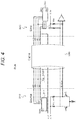
- FIG. 8 illustrates an exemplary detailed configuration of the transmission system illustrated in FIG. 7 .
- FIG. 9 illustrates an exemplary configuration of a transmission system.
- FIG. 10 is a flowchart for describing a series of operations when a cable in a transmission system is connected.
- FIG. 11 illustrates an exemplary configuration of a transmission system as a second embodiment.
- FIG. 12 illustrates an exemplary configuration of a transmission system as a third embodiment.
- FIG. 13 illustrates an exemplary configuration of a transmission system as a fourth embodiment.
- FIG. 14 illustrates an exemplary configuration of a transmission system as a fifth embodiment.
- FIG. 15 illustrates an exemplary configuration of a transmission system as a sixth embodiment.
- FIG. 16 illustrates an exemplary configuration of a transmission system as a seventh embodiment.
- FIG. 17 illustrates an exemplary configuration of a transmission system as an eighth embodiment.
- FIG. 18 illustrates an exemplary configuration of a transmission system as a ninth embodiment.
- FIG. 19 illustrates an exemplary configuration of a transmission system as a tenth embodiment.
- FIG. 20 illustrates an exemplary configuration of a transmission system as an eleventh embodiment.
- FIG. 21 illustrates an exemplary configuration of a transmission system as a twelfth embodiment.
- FIG. 22 explanatorily illustrates a method of transferring a connection sensed signal (hot plug detect (HPD) signal) to a source apparatus in order to shift to a normal sequence.
- HPD hot plug detect
- FIG. 23 explanatorily illustrates a method of transferring a connection sensed signal (HPD signal) to a source apparatus in order to shift to a normal sequence.
- HPD signal connection sensed signal
- FIG. 24 explanatorily illustrates a method of transferring a connection sensed signal (HPD signal) to a source apparatus in order to shift to a normal sequence.
- HPD signal connection sensed signal
- FIG. 25 explanatorily illustrates a method of transferring a connection sensed signal (HPD signal) to a source apparatus in order to shift to a normal sequence.
- HPD signal connection sensed signal
- FIG. 26 explanatorily illustrates a method of transferring a connection sensed signal (HPD signal) to a source apparatus in order to shift to a normal sequence.
- HPD signal connection sensed signal
- FIG. 27 explanatorily illustrates a method of transferring a connection sensed signal (HPD signal) to a source apparatus in order to shift to a normal sequence.
- HPD signal connection sensed signal
- FIGS. 28A, 28B, 28C, 28D, 28E, and 28F illustrate an exemplary configuration of a connector at the time of issuing notification of the presence of a register from a cable to a source apparatus, with a mechanical mechanism.
- FIGS. 29A, 29B, 29C, 29D, 29E, and 29F illustrate an exemplary configuration of a connector at the time of issuing notification of the presence of a register from a cable to a source apparatus, with a mechanical mechanism.
- FIGS. 30A, 30B, 30C, 30D, 30E, and 30F illustrate an exemplary configuration of a connector at the time of issuing notification of the presence of a register from a cable to a source apparatus, with a mechanical mechanism.
- FIGS. 31A, 31B, 31C, 31D, 31E, and 31F illustrate an exemplary configuration of a connector at the time of issuing notification of the presence of a register from a cable to a source apparatus, with a mechanical mechanism.
- FIG. 32 illustrates an exemplary configuration of a transmission system as a fourteenth embodiment.
- FIG. 33 illustrates an exemplary configuration of a transmission system as a fifteenth embodiment.
- FIG. 34 illustrates an exemplary configuration of a transmission system as the fifteenth embodiment.
- FIG. 1 illustrates an exemplary configuration of a transmission system 30 .
- the transmission system 30 is a high definition multimedia interface (HDMI) transmission system with HDMI as a digital interface.
- the transmission system 30 includes a source apparatus 310 serving as a transmission apparatus, a sink apparatus 320 serving as a reception apparatus, and an HDMI cable 330 that makes connection between the source apparatus 310 and the sink apparatus 320 .
- HDMI high definition multimedia interface
- a connection sensed signal is sent from the sink apparatus 320 to the source apparatus 310 through a hot plug detect (HPD) line 343 .
- HPD hot plug detect
- a control unit 311 of the source apparatus 310 reads, with a display data channel (DDC) line (serial data (SDA) line and serial clock (SCL) line), extended display identification data (EDID) including function information, from an EDID ROM 321 of the sink apparatus 320 , and grasps a function of the sink apparatus 320 .
- DDC display data channel
- SDA serial data
- SCL serial clock
- EDID extended display identification data
- FIG. 2 illustrates an exemplary detailed configuration of the transmission system 30 .
- the transmission channels of the transmission system 30 include three transition minimized differential signaling (TMDS) channels for transmitting, as digital signals, respective signals of video, audio, and control in TMDS data, and one TMDS clock channel for transmitting clock signals.
- TMDS transition minimized differential signaling
- Each TMDS channel has two differential signal lines. In the illustrated example, only one channel is illustrated.
- control signal lanes of an HDMI system include the display data channel (DDC) line, a consumer electronics control (CEC) line, an HPD line, a Utility line, and a +5-V power line.
- the DDC line has two signal lines, an SDA line and an SCL line included in the cable 330 .
- the DDC line is used for reading EDID from the EDID ROM 321 of the sink apparatus 320 by the source apparatus 310 .
- the CEC line is used to perform bidirectional communication of data for control, between the source apparatus 310 and the sink apparatus 320 .
- TMDS For the TMDS channel, a current driven type for transmitting “0” and “1” of data by drawing current to the source apparatus 310 side from a 50 ⁇ termination resistor linked to the sink apparatus 320 side is used. At this time, signals are transmitted differentially on the basis of differential signals of D and D (bar). Note that, in the illustrated example, use of a 50 ⁇ termination resistor on the source apparatus 310 side is exemplified; however, TMDS also enables driving with only the 50 ⁇ termination resistor on the sink apparatus side without using the 50 ⁇ termination resistor on the source apparatus 310 side.
- the HDMI standard prescribes the sequence when the cable 330 is connected.
- a voltage of 5 V is transmitted from the source apparatus 310 to the sink apparatus 320 via the +5-V power line.
- the transmitted 5 V is sensed in the sink apparatus 320
- the sensed 5 V is transmitted from the sink apparatus 320 to the source apparatus 310 via the HPD line.
- the control unit 311 of the source apparatus 310 determines that the cable 330 has been linked, and attempts to read, with the DDC line, the EDID in the EDID ROM 321 on the sink apparatus 320 side. Thereafter, with a control line such as the DDC line, exchange of signals such as high-bandwidth digital content protection system (HDCP) starts between the source apparatus 310 and the sink apparatus 320 , and unidirectional transmission of TMDS data with the TMDS channels starts from the source apparatus 310 to the sink apparatus 320 .
- HDMI high-bandwidth digital content protection system
- Use of a register prepared for a control unit 322 on the sink apparatus 320 side enables information exchange between the source apparatus 310 and the sink apparatus 320 .
- a register 331 is arranged parallel to a DDC line in a cable 330 . Note that, in FIGS. 3 and 4 , parts corresponding to those in FIGS. 1 and 2 are denoted by the same reference signs, and detailed description of the corresponding parts will be omitted appropriately.
- the source apparatus 310 on accessing a new address of the register 331 of the cable 330 , the source apparatus 310 also accesses a sink apparatus 320 . In a case where access to an unintended address has been made, it is likely that the sink apparatus 320 malfunctions.
- the method is viable in a case of a cable 330 having a new address.
- the cable 330 that is already available commercially and has no new address see FIGS. 1 and 2
- the cable 330 with the register 331 arranged in parallel to the DDC line see FIGS. 3 and 4
- access to a new address of the sink apparatus 320 is made from the source apparatus 310 .
- the sink apparatus 320 malfunctions.
- FIG. 7 illustrates an exemplary configuration of a transmission system 10 - 1 as a first embodiment.
- the transmission system 10 - 1 is a high definition multimedia interface (HDMI) transmission system with HDMI as a digital interface.
- the transmission system 10 - 1 includes a source apparatus 110 serving as a transmission apparatus, a sink apparatus 320 serving as a reception apparatus, and an HDMI cable 130 that makes connection between the source apparatus 110 and the sink apparatus 320 .
- FIG. 7 parts corresponding to those in FIG. 1 are illustrated with the same reference signs given.
- a buffer unit 132 is interposed between a display data channel (DDC) line 342 and a hot plug detect (HPD) line 343 .
- the buffer unit 132 has a register 131 having stored, for example, the specification data of the cable 130 (also including characteristic data of the cable 130 ), and a register 133 that temporarily stores extended display identification data (EDID) 321 read from the sink apparatus 320 .
- DDC display data channel
- HPD hot plug detect
- connection sensed signal (HPD signal) indicating that the connection between the apparatuses has been made is output from the HPD line 343 of the sink apparatus 320 .
- HPD signal a connection sensed signal
- the connection sensed signal is input to the buffer unit 132 and blocked, so that the connection sensed signal is not transferred to the source apparatus 110 at this point of time.
- the buffer unit 132 having sensed the connection sensed signal accesses an EDID ROM 321 of the sink apparatus 320 through the DDC line 342 , and temporarily saves the EDID that is the details thereof in the register 133 of the buffer unit 132 .
- the buffer unit 132 rewrites the EDID of the sink apparatus 320 temporarily saved in the register 133 with addition of information indicating the presence of the register 131 .
- the buffer unit 132 transfers a connection sensed signal (HPD signal) to the source apparatus 110 through the HPD line 343 .
- a control unit 111 of the source apparatus 110 having received the connection sensed signal attempts to access the EDID ROM 321 of the sink apparatus 320 through the DDC line 342 .
- the buffer unit 132 having received the access to the EDID ROM 321 from the source apparatus 110 does not pass the access to the sink apparatus 320 , and instead reads, from the register 133 , the EDID rewritten, in the buffer unit 132 , with addition of the information indicating the presence of the register 131 to send the rewritten EDID to the control unit 111 of the source apparatus 110 .
- the control unit 111 of the source apparatus 110 having received the EDID from the cable 130 senses that the cable 130 retains the register 131 and accesses the register 131 built in the cable 130 through the DCC line 342 . At this time, the buffer unit 132 does not pass the access information from the control unit 111 of the source apparatus 110 to the register 131 , to the sink apparatus 320 .
- the buffer unit 132 does not pass the access information from the control unit 111 of the source apparatus 110 to the EDID ROM 321 of the sink apparatus 320 and the access information to the register 131 in the buffer unit 132 , to the sink apparatus 321 .
- the other accesses to an address, however, are all passed through to the sink apparatus 320 .
- the source apparatus 110 accesses the register 131 ; however, the access information is not transferred to the sink apparatus 320 . Therefore, malfunction can be prevented from occurring in a sink apparatus 320 in which the corresponding address is not defined. Furthermore, the source apparatus 110 can acquire specification data such as the transmission speed and the required current amount of the cable 130 , from the register 131 of the cable 130 , so that the source apparatus 110 becomes able to operate stably according to the specification.
- FIG. 8 illustrates the transmission system 10 - 1 more specifically.
- the transmission channels of the transmission system 10 - 1 include three transition minimized differential signaling (TMDS) channels for transmitting, as digital signals, respective signals of video, audio, and control in TMDS data, and one TMDS clock channel for transmitting clock signals.
- TMDS transition minimized differential signaling
- Each TMDS channel has two differential signal lines. In the illustrated example, only one channel is illustrated.
- control signal lanes of an HDMI system include the display data channel (DDC) line, a consumer electronics control (CEC) line, an HPD line, a Utility line, and a +5-V power line.
- the DDC line has two signal lines, a serial data (SDA) line and a serial clock (SCL) line included in the cable 130 .
- the DDC line is used for reading EDID from the EDID ROM 321 of the sink apparatus 320 by the source apparatus 110 .
- the CEC line is used for performing bidirectional communication of data for control, between the source apparatus 110 and the sink apparatus 320 .
- TMDS For the TMDS channel, a current driven type for transmitting “0” and “1” 1 of data by drawing current to the source apparatus 110 side from a 50 ⁇ termination resistor linked to the sink apparatus 320 side is used. At this time, signals are transmitted differentially on the basis of differential signals of D and D (bar). Note that, in the illustrated example, use of a 50 ⁇ termination resistor on the source apparatus 110 side is exemplified; however, TMDS also enables driving with only the 50 ⁇ termination resistor on the sink apparatus side without using the 50 ⁇ termination resistor on the source apparatus 110 side.
- the buffer unit 132 is interposed between the DDC line and the HPD line.
- the buffer unit 132 has the register 131 present therein, the resistor having stored, for example, the specification data of the cable 130 (also including characteristic data of the cable 130 ), and the register 133 that temporarily stores the EDID read from the EDID ROM 321 of the sink apparatus 32 .
- FIG. 9 illustrates an exemplary configuration of a transmission system 10 - 1 A in this case.
- the transmission system 10 - 1 A includes a source apparatus 110 serving as a transmission apparatus, a sink apparatus 320 serving as a reception apparatus, and an HDMI cable 330 that makes connection between the source apparatus 110 and the sink apparatus 320 .
- parts corresponding to those in FIGS. 1 and 7 are denoted by the same reference signs, and detailed description of the corresponding parts will be omitted.
- a control unit 111 of the source apparatus 110 accesses an EDID ROM 321 of the sink apparatus 320 .
- EDID to be read does not include information indicating that a register is retained in the cable. Therefore, the control unit 111 of the source apparatus 110 senses that the cable 330 with no register retained has been connected, and does not access a register. As a result, access information to a register retained in the cable is not transferred to the sink apparatus 320 , and malfunction can be prevented from occurring in a sink apparatus 320 in which the corresponding address is not defined.
- the flowchart in FIG. 10 illustrates the series of operations when the cable in the transmission systems 10 - 1 in FIG. 7 or the cable in the transmission system 10 - 1 A in FIG. 9 is connected.
- step ST 1 the series of operations starts.
- step ST 2 the cable 130 is connected between the source apparatus 110 and the sink apparatus 320 in step ST 2 , supply of power from the source apparatus 110 through the power line 341 starts in step ST 3 .
- step ST 4 the buffer unit 132 of the cable 130 obtains the connection sensed signal (HPD signal) from the HPD line 343 . At this time, the connection sensed signal is not transferred to the source apparatus 110 . Then, in step ST 5 , the buffer unit 132 of the cable 130 reads EDID from the EDID ROM 321 of the sink apparatus 320 and temporarily saves the read EDID in the register 133 in the buffer unit 132 .
- HPD signal connection sensed signal
- step ST 6 the buffer unit 132 adds, to the EDID, information indicating that the register is retained in the cable, and rewrites the EDID. Thereafter, in step ST 7 , the buffer unit 132 of the cable 130 outputs a connection sensed signal to the source apparatus 110 through the HPD line 343 .
- step ST 8 the source apparatus 110 reads the EDID through the DDC line 342 .
- step ST 9 the source apparatus 110 determines whether or not the cable retains the register from the read EDID. When the information indicating that the cable retains the register is present in the EDID, the source apparatus 110 accesses the register 131 of the cable and acquires the details of retaining in step ST 10 .
- step ST 11 the buffer unit 132 of the cable 130 performs control such that the access information from the source apparatus 110 to the register 131 is not passed to the sink apparatus 320 .
- step ST 12 the series of operations ends.
- step ST 9 when no information indicating that a register is retained in the cable is present in the EDID, the series of operations ends immediately in step ST 12 . Note that, in a case of a cable with no register 131 retained, the procedures in steps ST 4 to ST 7 are skipped.
- FIG. 11 illustrates an exemplary configuration of a transmission system 10 - 2 as a second embodiment.
- This exemplary configuration is an example in which a cable issues notification, to the source apparatus, that the cable has a register with the cable specification data stored.
- the transmission system 10 - 2 is an HDMI transmission system with HDMI as a digital interface.
- the transmission system 10 - 2 includes a source apparatus 110 - 2 serving as a transmission apparatus, a sink apparatus 320 serving as a reception apparatus, and an HDMI cable 130 - 2 that makes connection between the source apparatus 110 - 2 and the sink apparatus 320 .
- FIG. 11 parts corresponding to those in FIG. 8 are denoted by the same reference signs, and detailed description of the corresponding parts will be omitted.
- a buffer unit 132 is disposed in the DDC line.
- the buffer unit 132 includes a register 131 having stored the specification data of the cable 130 (also including characteristic data of the cable 130 ) and the like.
- the buffer unit 132 does not pass access information from a control unit 111 of the source apparatus 110 - 2 to the register 131 , to the sink apparatus 320 .
- the cable 130 - 2 has a control unit (control block) 135 , and a switch 136 for generating pulse information provided in an HPD line.
- control unit control block
- switch 136 for generating pulse information provided in an HPD line.
- the buffer unit 132 and the control unit 135 are supplied with power from the HPD line.
- the source apparatus 110 - 2 includes a pulse detection unit 112 that detects pulse information in a case where the pulse information has been provided on the HPD line. When the pulse information is detected by the pulse detection unit 112 , the source apparatus 110 - 2 determines that the cable 130 - 2 retains the register 131 in a case of a predetermined pulse.
- the control unit 135 of the cable 130 - 2 controls such that the switch 136 is turned off (is opened) at the initial state or when a connection sensed signal (HPD signal) from the sink apparatus 320 is at “Low (0)”, and turned on (is closed)/turned off (is opened) alternately when the connection sensed signal (“HPD signal”) switches to “High (1)”, whereby the control unit 135 transmits pulse information of “High”/“Low” to the source apparatus 110 - 2 side through the HPD line.
- HPD signal connection sensed signal
- the source apparatus 110 - 2 determines that the cable 130 - 2 has the register 131 , and enables access to a new address.
- the pulse may be a monotone pulse, or may be a data string.
- a constant number of pulses may be repeatedly sent such that the source apparatus 110 - 2 can receive the pulse information reliably.
- the control unit 135 of the cable 130 - 2 turns on (closes) the switch 136 , thereby enabling shift to a normal sequence.
- the source apparatus 110 - 2 cannot sense pulse information from a linked cable, it can be determined that the cable has no new address or the cable is a legacy cable.
- the source apparatus 110 - 2 accesses the register 131 when it is sensed that the register 131 is present in the cable 130 - 2 . Therefore, register access is not performed for a cable having no register, and transmission of access information to a sink apparatus via the cable can be suppressed, so that malfunction can be prevented from occurring in the sink apparatus in which the corresponding address is not defined.
- the cable 130 - 2 provides information indicating the presence of the register 131 , to the source apparatus 110 - 2 . Therefore, it is recognized that the cable 130 - 2 retains the register 131 , and access to the register 131 can be performed to acquire storage data, in the source apparatus 110 - 2 . Furthermore, when access is made from the source apparatus 110 - 2 to the register 131 , the cable 130 - 2 blocks the access information at the buffer unit 132 such that the access information is not sent to the sink apparatus 320 . Therefore, transmission of the access information to a sink apparatus can be suppressed, so that malfunction can be prevented from occurring in the sink apparatus in which the corresponding address is not defined.
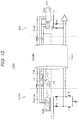
- FIG. 12 illustrates an exemplary configuration of a transmission system 10 - 3 as a third embodiment.
- This exemplary configuration is also an example in which a cable issues notification, to the source apparatus, that the cable has a register with the cable specification data stored.
- the transmission system 10 - 3 is an HDMI transmission system with HDMI as a digital interface.
- the transmission system 10 - 3 includes a source apparatus 110 - 3 serving as a transmission apparatus, a sink apparatus 320 serving as a reception apparatus, and an HDMI cable 130 - 3 that makes connection between the source apparatus 110 - 3 and the sink apparatus 320 .
- FIG. 12 parts corresponding to those in FIG. 11 are denoted by the same reference signs, and detailed description of the corresponding parts will be omitted.
- pulse information is suppliable from a control unit 135 to portions of the source apparatus 110 - 3 side with respect to a switch 136 , on an HPD line.
- the control unit 135 in the cable 130 - 3 When a connection sensed signal (HPD signal) from the sink apparatus 320 switches to “High (1)”, the control unit 135 in the cable 130 - 3 directly transmits the pulse information to the source apparatus 110 - 3 through the HPD line with the switch 136 kept off. After completing the transmission of the pulse information, the control unit 135 switches the switch 136 to on, and shifts to normal operation.
- HPD signal connection sensed signal
- “High” information can be transmitted to the source apparatus 110 - 3 , as a connection sensed signal (HPD signal) even until the switch 136 is turned on (closed) after the completion of pulse, thereby enabling shift to normal sequence mode sooner than the switch 136 is closed.
- HPD signal connection sensed signal
- the pulse information is directly transmitted from the control unit 135 in the cable 130 - 3 to the source apparatus 110 - 3 with the switch 136 kept off, thereby enabling elimination of feedback noise to the sink apparatus 320 when the pulse information is generated by directly turning on/off the switch 136 installed in the HPD line.
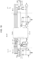
- FIG. 13 illustrates an exemplary configuration of a transmission system 10 - 4 as a fourth embodiment.
- This exemplary configuration is also an example in which a cable issues notification, to the source apparatus, that the cable has a register with the cable specification data stored.
- the transmission system 10 - 4 includes a source apparatus 110 - 4 serving as a transmission apparatus, a sink apparatus 320 serving as a reception apparatus, and an HDMI cable 130 - 4 that makes connection between the source apparatus 110 - 4 and the sink apparatus 320 .
- a source apparatus 110 - 4 serving as a transmission apparatus
- a sink apparatus 320 serving as a reception apparatus
- an HDMI cable 130 - 4 that makes connection between the source apparatus 110 - 4 and the sink apparatus 320 .
- FIG. 13 parts corresponding to those in FIG. 12 are denoted by the same reference signs, and detailed description of the corresponding parts will be omitted.
- a switch 136 of an HPD line is turned on/off with the recognition signal.
- FIG. 14 illustrates an exemplary configuration of a transmission system 10 - 5 as a fifth embodiment.
- This exemplary configuration is also an example in which a cable issues notification, to the source apparatus, that the cable has a register with the cable specification data stored.
- the transmission system 10 - 5 includes a source apparatus 110 - 5 serving as a transmission apparatus, a sink apparatus 320 serving as a reception apparatus, and an HDMI cable 130 - 5 that makes connection between the source apparatus 110 - 5 and the sink apparatus 320 .
- a source apparatus 110 - 5 serving as a transmission apparatus
- a sink apparatus 320 serving as a reception apparatus
- an HDMI cable 130 - 5 that makes connection between the source apparatus 110 - 5 and the sink apparatus 320 .
- FIG. 14 parts corresponding to those in FIG. 13 are denoted by the same reference signs, and detailed description of the corresponding parts will be omitted.
- the example indicates that the power supplied to a control unit 135 and a buffer unit 132 in the cable 130 - 5 is obtained from the HPD line, whereas for the transmission system 10 - 5 , the example indicates that power is obtained from a +5-V power line.
- FIG. 15 illustrates an exemplary configuration of a transmission system 10 - 6 as a sixth embodiment.
- This exemplary configuration is also an example in which a cable issues notification, to the source apparatus, that the cable has a register with the cable specification data stored.
- the transmission system 10 - 6 includes a source apparatus 110 - 6 serving as a transmission apparatus, a sink apparatus 320 serving as a reception apparatus, and an HDMI cable 130 - 6 that makes connection between the source apparatus 110 - 6 and the sink apparatus 320 .
- a source apparatus 110 - 6 serving as a transmission apparatus
- a sink apparatus 320 serving as a reception apparatus
- an HDMI cable 130 - 6 that makes connection between the source apparatus 110 - 6 and the sink apparatus 320 .
- FIG. 15 parts corresponding to those in FIG. 11 are denoted by the same reference signs, and detailed description of the corresponding parts will be omitted.
- This exemplary configuration is an example in which pulse information is transmitted from the cable 130 - 6 to the source apparatus 110 - 6 without using a switch of an HPD line.
- a method is conceivable in which a Utility line prescribed by HDMI is used to transmit pulse information.
- a control unit 135 in the cable 130 - 6 When sensing “High” information regarding a connection sensed signal (HPD signal), a control unit 135 in the cable 130 - 6 provides pulse information on the Utility line to transfer the pulse information to the source apparatus 110 - 6 .
- HPD signal connection sensed signal
- FIG. 16 illustrates an exemplary configuration of a transmission system 10 - 7 as a seventh embodiment.
- This exemplary configuration is also an example in which a cable issues notification, to the source apparatus, that the cable has a register with the cable specification data stored.
- the transmission system 10 - 7 includes a source apparatus 110 - 7 serving as a transmission apparatus, a sink apparatus 320 serving as a reception apparatus, and an HDMI cable 130 - 7 that makes connection between the transmission apparatus 110 - 7 and the sink apparatus 320 .
- a source apparatus 110 - 7 serving as a transmission apparatus
- a sink apparatus 320 serving as a reception apparatus
- an HDMI cable 130 - 7 that makes connection between the transmission apparatus 110 - 7 and the sink apparatus 320 .
- FIG. 16 parts corresponding to those in FIG. 15 are denoted by the same reference signs, and detailed description of the corresponding parts will be omitted.
- This exemplary configuration is an example in which a switch 137 is provided in a Utility line in order to avoid transmission of pulse information to the sink apparatus 320 through the Utility line.
- a control unit 135 can avoid the transmission by turning off the switch 137 during transmission of pulse information and turning on (closing) the switch 137 after completion of the transmission.
- FIG. 17 illustrates an exemplary configuration of a transmission system 10 - 8 as an eighth embodiment.
- This exemplary configuration is also an example in which a cable issues notification, to the source apparatus, that the cable has a register with the cable specification data stored.
- the transmission system 10 - 8 includes a source apparatus 110 - 8 serving as a transmission apparatus, a sink apparatus 320 serving as a reception apparatus, and an HDMI cable 130 - 8 that makes connection between the source apparatus 110 - 8 and the sink apparatus 320 .
- a source apparatus 110 - 8 serving as a transmission apparatus
- a sink apparatus 320 serving as a reception apparatus
- an HDMI cable 130 - 8 that makes connection between the source apparatus 110 - 8 and the sink apparatus 320 .
- FIG. 17 parts corresponding to those in FIG. 16 are denoted by the same reference signs, and detailed description of the corresponding parts will be omitted.
- the source apparatus 110 - 8 may issue notification, to the cable 130 - 8 , that the pulse information has been sensed, and then the switch 137 in the cable 130 - 8 may be closed.
- FIG. 18 illustrates an exemplary configuration of a transmission system 10 - 9 as a ninth embodiment.
- This exemplary configuration is also an example in which a cable issues notification, to the source apparatus, that the cable has a register with the cable specification data stored.
- the transmission system 10 - 9 includes a source apparatus 110 - 9 serving as a transmission apparatus, a sink apparatus 320 serving as a reception apparatus, and an HDMI cable 130 - 9 that makes connection between the source apparatus 110 - 9 and the sink apparatus 320 .
- a source apparatus 110 - 9 serving as a transmission apparatus
- a sink apparatus 320 serving as a reception apparatus
- an HDMI cable 130 - 9 that makes connection between the source apparatus 110 - 9 and the sink apparatus 320 .
- FIG. 18 parts corresponding to those in FIG. 17 are denoted by the same reference signs, and detailed description of the corresponding parts will be omitted.
- the example indicates that the power supplied to a control unit 135 and a buffer unit 132 in the cable 130 - 8 is obtained from the HPD line, whereas for the transmission system 10 - 9 , the example indicates that power is obtained from a +5-V power line.
- sensing of “High” of the connection sensed signal (HPD signal) is used as a trigger to start operation; however, in the transmission system 10 - 9 , sensing of “High” on the +5-V power line may be used as a trigger.
- FIG. 19 illustrates an exemplary configuration of a transmission system 10 - 10 as a tenth embodiment.
- This exemplary configuration is also an example in which a cable issues notification, to the source apparatus, that the cable has a register with the cable specification data stored.
- the transmission system 10 - 10 includes a source apparatus 110 - 10 serving as a transmission apparatus, a sink apparatus 320 serving as a reception apparatus, and an HDMI cable 130 - 10 that makes connection between the source apparatus 110 - 10 and the sink apparatus 320 .
- a source apparatus 110 - 10 serving as a transmission apparatus
- a sink apparatus 320 serving as a reception apparatus
- an HDMI cable 130 - 10 that makes connection between the source apparatus 110 - 10 and the sink apparatus 320 .
- FIG. 19 parts corresponding to those in FIG. 11 are given the same reference signs, and detailed description of the corresponding parts will be omitted.
- an active circuit for adjusting the characteristics of TMDS lines is built in the cable 130 - 10 .
- an active cable such as an active optical cable (AOC).
- the control unit 135 in the cable 130 - 10 turns on/off a low dropout (LDO) in a plug on the source apparatus 110 - 10 side to be able to control LDO output voltage, so that pulse information regarding “High”/“Low” can be transmitted to the source apparatus 110 - 10 side through the TMDS lines.
- LDO low dropout
- the voltage of the TMDS lines is monitored, so that the pulse information can be sensed.
- the LDO is turned on after transmission of the pulse information, the TMDS lines can operate normally.
- FIG. 20 illustrates an exemplary configuration of a transmission system 10 - 11 as an eleventh embodiment.
- This exemplary configuration is also an example in which a cable issues notification, to the source apparatus, that the cable has a register with the cable specification data stored.
- the transmission system 10 - 11 includes a source apparatus 110 - 11 serving as a transmission apparatus, a sink apparatus 320 serving as a reception apparatus, and an HDMI cable 130 - 11 that makes connection between the source apparatus 110 - 11 and the sink apparatus 320 .
- a source apparatus 110 - 11 serving as a transmission apparatus
- a sink apparatus 320 serving as a reception apparatus
- an HDMI cable 130 - 11 that makes connection between the source apparatus 110 - 11 and the sink apparatus 320 .
- FIG. 20 parts corresponding to those in FIG. 19 are denoted by the same reference signs, and detailed description of the corresponding parts will be omitted.
- the example indicates that the power supplied to a control unit 135 and a buffer unit 132 in the cable 130 - 11 is obtained from the HPD line, whereas for the transmission system 10 - 11 , the example indicates that power is obtained from a +5-V power line.
- sensing of “High” of the connection sensed signal (HPD signal) is used as a trigger to start operation; however, in the transmission system 10 - 11 , sensing of “High” on the +5-V power line may be used as a trigger.
- FIG. 21 illustrates an exemplary configuration of a transmission system 10 - 12 as a twelfth embodiment.
- This exemplary configuration is also an example in which a cable issues notification, to the source apparatus, that the cable has a register with the cable specification data stored.
- the transmission system 10 - 12 includes a source apparatus 110 - 12 serving as a transmission apparatus, a sink apparatus 320 serving as a reception apparatus, and an HDMI cable 130 - 12 that makes connection between the source apparatus 110 - 12 and the sink apparatus 320 .
- a source apparatus 110 - 12 serving as a transmission apparatus
- a sink apparatus 320 serving as a reception apparatus
- an HDMI cable 130 - 12 that makes connection between the source apparatus 110 - 12 and the sink apparatus 320 .
- FIG. 21 parts corresponding to those in FIG. 20 are denoted by the same reference signs, and detailed description of the corresponding parts will be omitted.
- the pulse information is reported to the source apparatus 110 - 12 by turning off/on the LDO, whereas the transmission system 10 - 12 has switches 138 and 139 provided in the lines linked to the termination resistor of the TMDS lines, and pulse information is reported to the source apparatus 110 - 12 by turning off/on the switches 138 and 139 .
- HPD signal connection sensed signal
- the switch 136 is turned off after transmission of the pulse information, the fact that the pulse information has been sensed from the source apparatus 110 - 2 is transmitted to the cable 130 - 2 through, for example, the DDC line, and the cable 130 - 2 closes the switch 136 thereafter.
- the cable 130 - 4 fixes the end of a pulse signal to Low and closes the switch 136 after sensing a feedback signal from the source apparatus 110 - 3 .
- the cable 130 - 5 fixes the end of a pulse signal to Low and closes the switch 136 after sensing a feedback signal from the source apparatus 110 - 4 .
- a switch 136 is provided in an HPD line and the switch 136 is closed with a feedback signal from a source apparatus as a trigger, as illustrated in FIGS. 22 to 24 .
- a switch 136 is provided in an HPD line as in FIGS. 25 to 27 and the switch 136 is closed, for example, with a feedback signal from the source apparatus through a DDC line used as a trigger.
- the cable transmits the pulse information to the source apparatus and issues notification of the presence of the register to the source apparatus.
- the presence of a register is notified with a mechanical mechanism from a cable to a source apparatus, or the source apparatus senses with the mechanical mechanism that the register is present in the cable.
- a mechanical mechanism of a connector is utilized.
- FIGS. 28A, 28B, 28C, 28D, 28E, and 28F illustrate an exemplary configuration of a connector.
- FIGS. 28A, 28B, and 28C respectively illustrate a plan view, a front view, and a perspective view of a receptacle 115 disposed in a source apparatus.
- FIGS. 28D, 28E, and 28F respectively illustrate a plan view, a front view, and a perspective view of a plug 140 provided at an end of a cable.
- An electrode 116 is provided on the receptacle 115 , and an electrode 141 is provided at the corresponding position also on the plug 140 .
- the electrode 116 and the electrode 141 come into contact with each other at the time when the receptacle 115 and the plug 140 are fitted, and the presence of a register is notified from the cable to the source apparatus. As a result, the presence of the register in the cable is sensed in the source apparatus.
- FIGS. 29A, 29B, 29C, 29D, 29E, and 29F illustrate another exemplary configuration of the connector.
- FIGS. 29A, 29B, and 29C respectively illustrate a plan view, a front view, and a perspective view of a receptacle 115 disposed in a source apparatus.
- FIGS. 29D, 29E, and 29F respectively illustrate a plan view, a front view, and a perspective view of a plug 140 provided at an end of a cable.
- the receptacle 115 is provided with a recess (groove) 117 , and a projection (protrusion) 142 is provided at the corresponding position also on the plug 140 . Fitting of the recess 117 and projection 142 is sensed when the receptacle 115 and the plug 140 are fitted, and the presence of a register is notified from the cable to the source apparatus. As a result, the presence of the register in the cable is sensed in the source apparatus.
- the receptacle 115 may be provided with a projection and the plug 140 may be provided with a recess.
- FIGS. 30A, 30B, 30C, 30D, 30E, and 30F illustrate yet another exemplary configuration of the connector.
- FIGS. 30A, 30B, and 30C respectively illustrate a plan view, a front view, and a perspective view of a receptacle 115 disposed in a source apparatus.
- FIGS. 30D, 30E, and 30F respectively illustrate a plan view, a front view, and a perspective view of a plug 140 provided at an end of a cable.
- a switch 118 is provided on a receptacle 115 , and a projection 143 is provided at the corresponding position also on the plug 140 .
- the switch 118 is pushed by the projection 143 when the receptacle 115 and the plug 140 are fitted, and the presence of a register is notified from the cable to the source apparatus. As a result, the presence of the register in the cable is sensed in the source apparatus.
- FIGS. 31A, 31B, 31C, 31D, 31E, and 31F illustrate yet another exemplary configuration of the connector.
- FIGS. 31A, 31B, and 31C respectively illustrate a plan view, a front view, and a perspective view of a receptacle 115 disposed in a source apparatus.
- FIGS. 31D, 31E, and 31F respectively illustrate a plan view, a front view, and a perspective view of a plug 140 provided at an end of a cable.
- the receptacle 115 is provided with a switch 118 and a projection 143 is provided at the corresponding position also on the plug 140 , which are the same as in the exemplary configuration of FIGS. 30A, 30B, 30C, 30D, 30E, and 30F .
- an insertion portion 146 of the plug 140 that is, a so-called port of the plug 140 is extended by the length of the projection 143 .
- the projection 143 of the plug 140 and the switch 118 of the receptacle 115 come into contact with each other at fitting; however, the contact quality of communication terminal provided originally can be maintained. Furthermore, in this case, even if the new plug 140 is inserted into a legacy receptacle, the contact quality of the communication terminal can be maintained.
- FIG. 32 illustrates an exemplary configuration of a transmission system 10 - 14 as a fourteenth embodiment.
- This exemplary configuration is an example in which a cable issues, with a mechanical mechanism (see FIGS. 28A, 28B, 28C, 28D, 28E, 28F, 29A, 29B, 29C, 29D, 29E, 29F, 30A, 30B, 30C, 30D, 30E, 30F, 31A, 31B, 31C , 31 D, 31 E, and 31 F), notification to a source apparatus that the cable has a register with the cable specification data stored.
- a mechanical mechanism see FIGS. 28A, 28B, 28C, 28D, 28E, 28F, 29A, 29B, 29C, 29D, 29E, 29F, 30A, 30B, 30C, 30D, 30E, 30F, 31A, 31B, 31C , 31 D, 31 E, and 31 F
- the transmission system 10 - 14 includes a source apparatus 110 - 14 serving as a transmission apparatus, a sink apparatus 320 serving as a reception apparatus, and an HDMI cable 130 - 14 that makes connection between the source apparatus 110 - 14 and the sink apparatus 320 .
- a source apparatus 110 - 14 serving as a transmission apparatus
- a sink apparatus 320 serving as a reception apparatus
- an HDMI cable 130 - 14 that makes connection between the source apparatus 110 - 14 and the sink apparatus 320 .
- FIG. 32 parts corresponding to those in FIG. 11 are denoted by the same reference signs, and detailed description of the corresponding parts will be omitted.
- the source apparatus 110 - 14 includes a mechanical sensing mechanism 119 .
- the control unit 111 of the source apparatus 110 - 14 determines that access to the register 131 of the cable 130 - 14 is allowable.
- FIG. 33 illustrates an exemplary configuration of a transmission system 10 - 15 as a fifteenth embodiment.
- This configuration example is also an example in which a cable issues, with a mechanical mechanism (see FIGS. 28A, 28B, 28C, 28D, 28E, 28F, 29A, 29B, 29C, 29D, 29E, 29F, 30A, 30B, 30C, 30D, 30E, 30F, 31A, 31B, 31C , 31 D, 31 E, and 31 F), notification to a source apparatus that the cable has a register with the cable specification data stored.
- a mechanical mechanism see FIGS. 28A, 28B, 28C, 28D, 28E, 28F, 29A, 29B, 29C, 29D, 29E, 29F, 30A, 30B, 30C, 30D, 30E, 30F, 31A, 31B, 31C , 31 D, 31 E, and 31 F
- the transmission system 10 - 15 includes a source apparatus 110 - 15 serving as a transmission apparatus, a sink apparatus 320 serving as a reception apparatus, and an HDMI cable 130 - 15 that makes connection between the source apparatus 110 - 15 and the sink apparatus 320 .
- a source apparatus 110 - 15 serving as a transmission apparatus
- a sink apparatus 320 serving as a reception apparatus
- an HDMI cable 130 - 15 that makes connection between the source apparatus 110 - 15 and the sink apparatus 320 .
- FIG. 33 parts corresponding to those in FIG. 32 are denoted by the same reference signs, and detailed description of the corresponding parts will be omitted.
- a cable 130 - 15 also includes a mechanical sensing mechanism 144 .
- the source apparatus 110 - 15 and the cable 130 - 15 are connected, it is sensed that the cable 130 - 15 has been connected to the corresponding source apparatus 110 - 15 and information regarding the sensing is sent to a control unit 145 , at the mechanical sensing mechanism 144 .
- control unit 145 controls the operation of a buffer unit 132 on the basis of the information regarding the sensing. For example, in a case where no mechanical sensing has been made, the control unit 145 sets through mode in which a DDC signal is passed completely. In contrast, in a case where mechanical sensing has been made, the control unit 145 sets mode in which accessing to a register 131 from the source apparatus 110 - 15 is kept in the cable only, so that the power consumption of a buffer unit 132 can be controlled.
- FIG. 34 illustrates an exemplary configuration of a transmission system 10 - 16 as a sixteenth embodiment.
- This exemplary configuration is an example in which control is performed such that the source apparatus senses, with a mechanical mechanism, the ability (capability) of flowing sufficient current and then a cable draws current from the source apparatus, that is, receives supply of current.
- the transmission system 10 - 16 includes a source apparatus 110 - 16 serving as a transmission apparatus, a sink apparatus 320 serving as a reception apparatus, and an HDMI cable 130 - 16 that makes connection between the source apparatus 110 - 16 and the sink apparatus 320 .
- a source apparatus 110 - 16 serving as a transmission apparatus
- a sink apparatus 320 serving as a reception apparatus
- an HDMI cable 130 - 16 that makes connection between the source apparatus 110 - 16 and the sink apparatus 320 .
- FIG. 34 parts corresponding to those in FIGS. 19 and 33 are denoted by the same reference signs, and detailed description of the corresponding parts will be omitted.
- the source apparatus 110 - 16 includes a mechanical sensing mechanism 119 .
- the cable 130 - 16 serves as an active device that consumes a large current, and in this example, the cable 130 - 16 is an active optical cable (AOC) with an active circuit built therein.
- AOC active optical cable
- Information regarding sensing of the mechanical sensing mechanism 119 is sent to a control unit 111 .
- the control unit 111 of the source apparatus 110 - 14 recognizes that the cable 130 - 16 is a cable having an active device that consumes a large current.
- the cable 130 - 16 is also provided with a mechanical sensing mechanism 144 .
- the source apparatus 110 - 16 and the cable 130 - 16 are connected, it is sensed that the cable 130 - 16 has been connected to the corresponding source apparatus 110 - 16 , that is, the source apparatus 110 - 16 having an ability (capability) of supplying a large current to the cable 130 - 16 , and the information regarding the sensing is sent to a control unit 145 , at the mechanical sensing mechanism 144 .
- the control unit 145 controls the operation of the active circuit on the basis of the information regarding the sensing. For example, in a case where no mechanical sensing has been made, the control unit 145 sets non-operation mode as a state where power supply to the active circuit is stopped. In contrast, in a case where mechanical sensing has been made, the control unit 145 sets operation mode as a state where power supply to the active circuit is performed.
- control can be performed such that power supply is received only when the source apparatus can supply a predetermined current. Alternatively, the current amount consumed by the cable 130 - 16 is reduced to enable operation in low power mode.
- the sensing is performed with the mechanical mechanism. Thus, sensing is not performed with a signal from a DDC line or the like, and control can be performed easily and reliably.
- the present technology is also similarly applicable to a cable that adopts a mechanism defined in the “VESA Plug and Display (P & D) Specification” for connecting between a transmission apparatus and a reception apparatus.
- P & D VESA Plug and Display
- the present technology is also applicable to display visual interface (DVI), mobile high-definition link (MHL), Display Port, and the like.
- DVI display visual interface
- MHL mobile high-definition link
- Display Port Display Port
- the present technology is not limited to an active optical cable (AOC) and an active copper cable (ACC), but is also applicative to, for example, wireless communication.
- the present technology can also have configurations as described below.
- a transmission apparatus including:
- an inquiry unit configured to perform an inquiry about presence or absence of a register to a cable connected between the transmission apparatus and a reception apparatus;
- an information reception unit configured to receive information indicating the presence or absence of the register from the cable in response to the inquiry
- an access unit configured to access the register to acquire storage data or write in the storage data, when the information indicates the presence of the register.
- the inquiry unit performs the inquiry after power is supplied to the reception apparatus via the cable.
- the information reception unit performs reading of function information regarding the reception apparatus through the cable, on the basis of a connection sensed signal from the cable, and receives the information indicating the presence or absence of the register.
- the cable serves as a high definition multimedia interface (HDMI) cable
- the information reception unit receives the connection sensed signal through a hot plug detect (HPD) line and reads the function information through a display data channel (DDC) line.
- HPD hot plug detect
- DDC display data channel
- a method of controlling a transmission apparatus including:
- an inquiry reception unit configured to receive an inquiry about presence or absence of the register from the transmission apparatus
- an information providing unit configured to provide information indicating the presence of the register to the transmission apparatus in response to the inquiry
- a buffer unit configured to perform blocking when access to the register is made from the transmission apparatus, such that information regarding the access is not sent to the reception apparatus.
- the inquiry reception unit receives the inquiry after receiving a connection sensed signal sent from the reception apparatus corresponding to power supplied from the transmission apparatus to the reception apparatus via the cable.
- the information providing unit sends a connection sensed signal to the transmission apparatus and causes the transmission apparatus to read the retained function information.
- a transmission apparatus including:
- a sensing unit configured to sense that a register is present in a cable connected between the transmission apparatus and a reception apparatus
- an access unit configured to access, when the presence of the register is sensed, the register to acquire storage data or write in the storage data.
- the sensing unit senses that the register is present in the cable, on the basis of a notification signal indicating the presence of the register sent from the cable.
- the sensing unit receives pulse information provided on a predetermined line of the cable, as the notification signal.
- the sensing unit senses that the register is present in the cable, with a mechanical mechanism.
- a method of controlling a transmitting apparatus including:
- an information providing unit configured to provide information indicating presence of the register to the transmission apparatus
- a buffer unit configured to perform blocking when access to the register is made from the transmission apparatus, such that information regarding the access is not sent to the reception apparatus.
- the information providing unit provides the information indicating the presence of the register to the transmission apparatus through a predetermined line of the cable.
- the information providing unit provides the information indicating the presence of the register to the transmission apparatus, with a mechanical mechanism.
- a transmission apparatus including:
- a notification unit configured to issue notification that a predetermined current is suppliable to a cable connected between the transmission apparatus and a reception apparatus.
- the notification unit issues the notification, with a mechanical mechanism.
- a reception unit configured to receive notification that a predetermined current is suppliable from the transmission apparatus
- control unit configured to perform control such that the supply of the current is received from the transmission apparatus after the reception of the notification.
- reception unit receives the notification, with a mechanical mechanism.
Abstract
Description
- Patent Document 1: Japanese Patent Application Laid-Open No. 2015-111418
- 10-1 to 10-16, 10-1A Transmission system
- 110, 110-2 to 110-16 Source apparatus
- 111 Control unit
- 112 Pulse detection unit
- 115 Receptacle
- 116 Electrode
- 117 Recess
- 118 Switch
- 119 Mechanical sensing mechanism
- 130, 130-2 to 130-16 HDMI cable
- 131 Register
- 132 Buffer unit
- 133 Register
- 135 Control unit
- 136 to 139 Switch
- 140 Plug
- 141 Electrode
- 142 Projection
- 143 Projection
- 144 Mechanical sensing mechanism
- 145 Control unit
- 146 Terminal
- 320 Sink apparatus
- 321 EDID ROM
- 322 Control unit
- 341 Power line
- 342 DCC line
- 343 HPD line
Claims (21)
Applications Claiming Priority (4)
| Application Number | Priority Date | Filing Date | Title |
|---|---|---|---|
| JPJP2017-143134 | 2017-07-24 | ||
| JP2017143134 | 2017-07-24 | ||
| JP2017-143134 | 2017-07-24 | ||
| PCT/JP2018/026839 WO2019021901A1 (en) | 2017-07-24 | 2018-07-18 | Transmission device, control method for transmission device, and cable |
Publications (2)
| Publication Number | Publication Date |
|---|---|
| US20200142639A1 US20200142639A1 (en) | 2020-05-07 |
| US11216213B2 true US11216213B2 (en) | 2022-01-04 |
Family
ID=65040164
Family Applications (1)
| Application Number | Title | Priority Date | Filing Date |
|---|---|---|---|
| US16/631,209 Active 2038-08-08 US11216213B2 (en) | 2017-07-24 | 2018-07-18 | Transmission apparatus, method of controlling transmission apparatus, and cable |
Country Status (4)
| Country | Link |
|---|---|
| US (1) | US11216213B2 (en) |
| JP (1) | JP7310604B2 (en) |
| CN (1) | CN110945458B (en) |
| WO (1) | WO2019021901A1 (en) |
Families Citing this family (4)
| Publication number | Priority date | Publication date | Assignee | Title |
|---|---|---|---|---|
| WO2020226674A1 (en) * | 2019-05-06 | 2020-11-12 | Huawei Technologies Co. Ltd. | Display of video content on a sink device using advanced features |
| CN111163271A (en) * | 2019-12-13 | 2020-05-15 | 晶晨半导体(深圳)有限公司 | EDID version switching method for solving HDMI compatibility problem |
| US10949377B1 (en) * | 2020-01-22 | 2021-03-16 | Luca Zanetti | Multimedia cable with dedicated infrared channel |
| JP7404175B2 (en) | 2020-07-14 | 2023-12-25 | 株式会社東芝 | Communication equipment, cable equipment and display equipment |
Citations (11)
| Publication number | Priority date | Publication date | Assignee | Title |
|---|---|---|---|---|
| JP2004260742A (en) | 2003-02-27 | 2004-09-16 | Noritz Corp | Communication signal repeating method, its repeating apparatus and home facility equipment system |
| US20050182876A1 (en) | 2004-02-18 | 2005-08-18 | Silicon Image, Inc. | Cable with circuitry for asserting stored cable data or other information to an external device or user |
| US20060031611A1 (en) * | 2004-08-05 | 2006-02-09 | Sumitomo Electric Industries, Ltd. | Digital video signal interface module |
| US20110091219A1 (en) * | 2005-09-15 | 2011-04-21 | Finisar Corporation | Laser drivers for closed path optical cables |
| JP2012075067A (en) | 2010-09-30 | 2012-04-12 | Sony Corp | Transmitter, transmission method, receiver, reception method, transmission-reception system, and cable |
| JP2012124808A (en) | 2010-12-10 | 2012-06-28 | Toshiba Corp | Bidirectional communication interface device and bidirectional communication interface system |
| WO2014112090A1 (en) | 2013-01-17 | 2014-07-24 | 株式会社日立製作所 | Disk array system and cable information setting method |
| JP2015111418A (en) | 2014-11-17 | 2015-06-18 | ソニー株式会社 | Cable |
| US20170006336A1 (en) * | 2014-03-12 | 2017-01-05 | Lg Electronics Inc. | Device and method for transmitting and receiving data using hdmi |
| US20170116146A1 (en) * | 2015-10-26 | 2017-04-27 | Le Holdings (Beijing) Co., Ltd. | Control method and control device for a mobile terminal |
| US10216683B2 (en) * | 2015-11-13 | 2019-02-26 | Mstar Semiconductor, Inc. | Multimedia communication apparatus and control method for multimedia data transmission over standard cable |
-
2018
- 2018-07-18 US US16/631,209 patent/US11216213B2/en active Active
- 2018-07-18 CN CN201880048119.2A patent/CN110945458B/en active Active
- 2018-07-18 WO PCT/JP2018/026839 patent/WO2019021901A1/en active Application Filing
- 2018-07-18 JP JP2019532532A patent/JP7310604B2/en active Active
Patent Citations (19)
| Publication number | Priority date | Publication date | Assignee | Title |
|---|---|---|---|---|
| JP2004260742A (en) | 2003-02-27 | 2004-09-16 | Noritz Corp | Communication signal repeating method, its repeating apparatus and home facility equipment system |
| US20050182876A1 (en) | 2004-02-18 | 2005-08-18 | Silicon Image, Inc. | Cable with circuitry for asserting stored cable data or other information to an external device or user |
| KR20060106842A (en) | 2004-02-18 | 2006-10-12 | 실리콘 이미지, 인크.(델라웨어주 법인) | Cable with circuitry for asserting stored cable data or other information to an external device or user |
| CN1898658A (en) | 2004-02-18 | 2007-01-17 | 晶像股份有限公司 | Cable with circuitry for asserting stored cable data or other information to an external device or user |
| JP2007535235A (en) | 2004-02-18 | 2007-11-29 | シリコン イメージ,インコーポレイテッド | Cables with circuitry to reveal stored cable data or other information to external devices or users |
| US20060031611A1 (en) * | 2004-08-05 | 2006-02-09 | Sumitomo Electric Industries, Ltd. | Digital video signal interface module |
| US20110091219A1 (en) * | 2005-09-15 | 2011-04-21 | Finisar Corporation | Laser drivers for closed path optical cables |
| US8843679B2 (en) * | 2010-09-30 | 2014-09-23 | Sony Corporation | Transmitting device, transmitting method, receiving device, receiving method, transmitting/receiving system, and cable |
| JP2012075067A (en) | 2010-09-30 | 2012-04-12 | Sony Corp | Transmitter, transmission method, receiver, reception method, transmission-reception system, and cable |
| CN103141063A (en) | 2010-09-30 | 2013-06-05 | 索尼公司 | Transmitting device, transmitting method, receiving device, receiving method, transmitting/receiving system, and cable |
| US20130191563A1 (en) | 2010-09-30 | 2013-07-25 | Sony Corporation | Transmitting device, transmitting method, receiving device, receiving method, transmitting/receiving system, and cable |
| KR20140007324A (en) | 2010-09-30 | 2014-01-17 | 소니 주식회사 | Transmission apparatus, transmission method, reception apparatus, reception method, transmission/reception system, and cable |
| JP2012124808A (en) | 2010-12-10 | 2012-06-28 | Toshiba Corp | Bidirectional communication interface device and bidirectional communication interface system |
| WO2014112090A1 (en) | 2013-01-17 | 2014-07-24 | 株式会社日立製作所 | Disk array system and cable information setting method |
| US20150317092A1 (en) | 2013-01-17 | 2015-11-05 | Hitachi, Ltd. | Disk array system and cable information setting method |
| US20170006336A1 (en) * | 2014-03-12 | 2017-01-05 | Lg Electronics Inc. | Device and method for transmitting and receiving data using hdmi |
| JP2015111418A (en) | 2014-11-17 | 2015-06-18 | ソニー株式会社 | Cable |
| US20170116146A1 (en) * | 2015-10-26 | 2017-04-27 | Le Holdings (Beijing) Co., Ltd. | Control method and control device for a mobile terminal |
| US10216683B2 (en) * | 2015-11-13 | 2019-02-26 | Mstar Semiconductor, Inc. | Multimedia communication apparatus and control method for multimedia data transmission over standard cable |
Non-Patent Citations (1)
| Title |
|---|
| International Search Report and Written Opinion of PCT Application No. PCT/JP2018/026839, dated Oct. 23, 2018, 10 pages of ISRWO. |
Also Published As
| Publication number | Publication date |
|---|---|
| CN110945458A (en) | 2020-03-31 |
| WO2019021901A1 (en) | 2019-01-31 |
| US20200142639A1 (en) | 2020-05-07 |
| JP7310604B2 (en) | 2023-07-19 |
| JPWO2019021901A1 (en) | 2020-06-11 |
| CN110945458B (en) | 2023-09-12 |
Similar Documents
| Publication | Publication Date | Title |
|---|---|---|
| US11216213B2 (en) | Transmission apparatus, method of controlling transmission apparatus, and cable | |
| US10038871B2 (en) | Method and device for transmitting and receiving power using HDMI | |
| CN106354245B (en) | Receiving device and power supply method | |
| EP2692118B1 (en) | Method, apparatus and system for transitioning an audio/video device between a source and a sink mode | |
| US11375270B2 (en) | Cable, method of controlling cable, connection device, electronic device, and method of controlling electronic device | |
| EP1805594A4 (en) | Display apparatus and control method thereof | |
| EP3306946B1 (en) | Method for transmitting and receiving power using hdmi and apparatus therefor | |
| US20200212898A1 (en) | Cable and connection device | |
| US20100079444A1 (en) | Displayport sleep behavior | |
| US11442523B2 (en) | Cable and connection device | |
| KR100744077B1 (en) | Ddc(display data channel) communication module | |
| US11662393B2 (en) | Cable, method for controlling cable, transmission device, method for controlling transmission device, reception device, and method for controlling reception device | |
| CN102194436A (en) | Insulation protective circuit for DDC (Direct Digital Control) interface | |
| CN201550224U (en) | DVI communication data transmission device | |
| US10802558B2 (en) | Method for transmitting and receiving power by using HDMI and device therefor | |
| US11949959B2 (en) | Cable, control information transmission method for cable, connection apparatus, electronic equipment, and output data controlling method for electronic equipment | |
| JP2015167396A (en) | Sink apparatus and power supply method | |
| WO2019021900A1 (en) | Transmission device, transmission method, cable, cable processing method, reception device and reception method |
Legal Events
| Date | Code | Title | Description |
|---|---|---|---|
| FEPP | Fee payment procedure |
Free format text: ENTITY STATUS SET TO UNDISCOUNTED (ORIGINAL EVENT CODE: BIG.); ENTITY STATUS OF PATENT OWNER: LARGE ENTITY |
|
| STPP | Information on status: patent application and granting procedure in general |
Free format text: DOCKETED NEW CASE - READY FOR EXAMINATION |
|
| AS | Assignment |
Owner name: SONY CORPORATION, JAPAN Free format text: ASSIGNMENT OF ASSIGNORS INTEREST;ASSIGNORS:YAMAMOTO, MASANARI;MORITA, HIROSHI;TOBA, KAZUAKI;AND OTHERS;SIGNING DATES FROM 20200217 TO 20200218;REEL/FRAME:052243/0652 |
|
| STPP | Information on status: patent application and granting procedure in general |
Free format text: NON FINAL ACTION MAILED |
|
| STPP | Information on status: patent application and granting procedure in general |
Free format text: RESPONSE TO NON-FINAL OFFICE ACTION ENTERED AND FORWARDED TO EXAMINER |
|
| STPP | Information on status: patent application and granting procedure in general |
Free format text: NOTICE OF ALLOWANCE MAILED -- APPLICATION RECEIVED IN OFFICE OF PUBLICATIONS |
|
| STPP | Information on status: patent application and granting procedure in general |
Free format text: AWAITING TC RESP., ISSUE FEE NOT PAID |
|
| STPP | Information on status: patent application and granting procedure in general |
Free format text: NOTICE OF ALLOWANCE MAILED -- APPLICATION RECEIVED IN OFFICE OF PUBLICATIONS |
|
| STPP | Information on status: patent application and granting procedure in general |
Free format text: PUBLICATIONS -- ISSUE FEE PAYMENT VERIFIED |
|
| STCF | Information on status: patent grant |
Free format text: PATENTED CASE |