US11216194B2 - Memory management system and method thereof - Google Patents
Memory management system and method thereof Download PDFInfo
- Publication number
- US11216194B2 US11216194B2 US16/812,580 US202016812580A US11216194B2 US 11216194 B2 US11216194 B2 US 11216194B2 US 202016812580 A US202016812580 A US 202016812580A US 11216194 B2 US11216194 B2 US 11216194B2
- Authority
- US
- United States
- Prior art keywords
- memory
- host devices
- physical host
- processing unit
- central processing
- Prior art date
- Legal status (The legal status is an assumption and is not a legal conclusion. Google has not performed a legal analysis and makes no representation as to the accuracy of the status listed.)
- Active
Links
Images


Classifications
-
- G—PHYSICS
- G06—COMPUTING; CALCULATING OR COUNTING
- G06F—ELECTRIC DIGITAL DATA PROCESSING
- G06F3/00—Input arrangements for transferring data to be processed into a form capable of being handled by the computer; Output arrangements for transferring data from processing unit to output unit, e.g. interface arrangements
- G06F3/06—Digital input from, or digital output to, record carriers, e.g. RAID, emulated record carriers or networked record carriers
- G06F3/0601—Interfaces specially adapted for storage systems
- G06F3/0628—Interfaces specially adapted for storage systems making use of a particular technique
- G06F3/0629—Configuration or reconfiguration of storage systems
- G06F3/0631—Configuration or reconfiguration of storage systems by allocating resources to storage systems
-
- G—PHYSICS
- G06—COMPUTING; CALCULATING OR COUNTING
- G06F—ELECTRIC DIGITAL DATA PROCESSING
- G06F13/00—Interconnection of, or transfer of information or other signals between, memories, input/output devices or central processing units
- G06F13/14—Handling requests for interconnection or transfer
- G06F13/16—Handling requests for interconnection or transfer for access to memory bus
- G06F13/1668—Details of memory controller
-
- G—PHYSICS
- G06—COMPUTING; CALCULATING OR COUNTING
- G06F—ELECTRIC DIGITAL DATA PROCESSING
- G06F13/00—Interconnection of, or transfer of information or other signals between, memories, input/output devices or central processing units
- G06F13/38—Information transfer, e.g. on bus
- G06F13/40—Bus structure
- G06F13/4004—Coupling between buses
- G06F13/4027—Coupling between buses using bus bridges
-
- G—PHYSICS
- G06—COMPUTING; CALCULATING OR COUNTING
- G06F—ELECTRIC DIGITAL DATA PROCESSING
- G06F13/00—Interconnection of, or transfer of information or other signals between, memories, input/output devices or central processing units
- G06F13/38—Information transfer, e.g. on bus
- G06F13/42—Bus transfer protocol, e.g. handshake; Synchronisation
- G06F13/4282—Bus transfer protocol, e.g. handshake; Synchronisation on a serial bus, e.g. I2C bus, SPI bus
-
- G—PHYSICS
- G06—COMPUTING; CALCULATING OR COUNTING
- G06F—ELECTRIC DIGITAL DATA PROCESSING
- G06F3/00—Input arrangements for transferring data to be processed into a form capable of being handled by the computer; Output arrangements for transferring data from processing unit to output unit, e.g. interface arrangements
- G06F3/06—Digital input from, or digital output to, record carriers, e.g. RAID, emulated record carriers or networked record carriers
- G06F3/0601—Interfaces specially adapted for storage systems
- G06F3/0602—Interfaces specially adapted for storage systems specifically adapted to achieve a particular effect
- G06F3/0604—Improving or facilitating administration, e.g. storage management
-
- G—PHYSICS
- G06—COMPUTING; CALCULATING OR COUNTING
- G06F—ELECTRIC DIGITAL DATA PROCESSING
- G06F3/00—Input arrangements for transferring data to be processed into a form capable of being handled by the computer; Output arrangements for transferring data from processing unit to output unit, e.g. interface arrangements
- G06F3/06—Digital input from, or digital output to, record carriers, e.g. RAID, emulated record carriers or networked record carriers
- G06F3/0601—Interfaces specially adapted for storage systems
- G06F3/0628—Interfaces specially adapted for storage systems making use of a particular technique
- G06F3/0638—Organizing or formatting or addressing of data
- G06F3/064—Management of blocks
-
- G—PHYSICS
- G06—COMPUTING; CALCULATING OR COUNTING
- G06F—ELECTRIC DIGITAL DATA PROCESSING
- G06F3/00—Input arrangements for transferring data to be processed into a form capable of being handled by the computer; Output arrangements for transferring data from processing unit to output unit, e.g. interface arrangements
- G06F3/06—Digital input from, or digital output to, record carriers, e.g. RAID, emulated record carriers or networked record carriers
- G06F3/0601—Interfaces specially adapted for storage systems
- G06F3/0628—Interfaces specially adapted for storage systems making use of a particular technique
- G06F3/0638—Organizing or formatting or addressing of data
- G06F3/0644—Management of space entities, e.g. partitions, extents, pools
-
- G—PHYSICS
- G06—COMPUTING; CALCULATING OR COUNTING
- G06F—ELECTRIC DIGITAL DATA PROCESSING
- G06F3/00—Input arrangements for transferring data to be processed into a form capable of being handled by the computer; Output arrangements for transferring data from processing unit to output unit, e.g. interface arrangements
- G06F3/06—Digital input from, or digital output to, record carriers, e.g. RAID, emulated record carriers or networked record carriers
- G06F3/0601—Interfaces specially adapted for storage systems
- G06F3/0668—Interfaces specially adapted for storage systems adopting a particular infrastructure
- G06F3/0671—In-line storage system
- G06F3/0673—Single storage device
-
- G—PHYSICS
- G06—COMPUTING; CALCULATING OR COUNTING
- G06F—ELECTRIC DIGITAL DATA PROCESSING
- G06F2213/00—Indexing scheme relating to interconnection of, or transfer of information or other signals between, memories, input/output devices or central processing units
- G06F2213/0026—PCI express
Definitions
- the instant disclosure relates to a memory management system and a method thereof; in particular, to a memory management system and a method thereof that help the central processing unit of a server to do memory management for a device system.
- the virtual device can be considered an interface between the software and the computer system to provide resources of the computer system to the software.
- the software is an operating system.
- the operating system can access the resources of the computer system through the virtual device.
- a plurality of virtual devices can be configured in one computer system, and different virtual devices can run different operating systems.
- the Windows® operating system and the Linux operating system can be respectively run by different virtual devices in the same computer system.
- the virtual device must be a host device. According to the requirements of different users, different host devices may be assigned different tasks. Thus, how to effectively allocate resources (especially the memory) of a computer system to different host devices according to requirements of different users is still worth discussing.
- a number of servers each including a processor, memory, hard disk, network card, and power unit are mounted in a server rack that is a frame for mounting multiple electronic equipment modules, such as the servers.
- multiple servers may be coupled together to perform common tasks.
- the rack-mounted servers have the advantages of expandability and effectiveness.
- hundreds or thousands of servers are mounted in a number of server racks, causing issues of physical space usage, heat dissipation, computing resource management, and complexity of deploying a fully configurable system with the rack-mounted servers.
- this memory management method can be used to help a central processing unit of a server to do memory management for a device system.
- a memory block is connected to the central processing unit of the server, and there is a plurality of host devices configured in the device system.
- This memory management method comprises: determining a number of the host devices configured in the device system; providing a corresponding device code to each host device; determining the memory capacity of the memory block; and allocating memory to each host device and accordingly building an allocation table.
- the central processing unit responds to the host device according to the allocation table, such that the host device uses the memory block to access data.
- the instant disclosure further provides a memory management system.
- this memory management system can be configured on a mother board of a server to help a central processing unit of the server to do memory management.
- a memory block is connected to the central processing unit of the server, and there is a plurality of host devices configured in the device system.
- the memory management system comprises a memory allocation module and an interconnection module.
- the memory allocation module is configured for: determining a number of the host devices configured in the device system; providing a corresponding device code to each host device; determining the memory capacity of the memory block; and allocating memory to each host device and accordingly building an allocation table.
- the interconnection module is connected between the memory allocation module and the host devices of the device system.
- the interconnection module converts the request signal and transmits the converted request signal to the central processing unit.
- the central processing unit responds to the request signal of the host device according to the allocation table such that the host device uses the memory block to access data.
- the major achievement of the memory management system and the memory management method provided by the above embodiments of the instant disclosure is to help the central processing unit to allocate memory to each host device to use.
- the memory management system provided by the instant disclosure can be directly configured on the mother board of a server.
- a customized memory management system can be built. After that, this customized memory management system can be directly configured on the mother board of a server of the general client or the enterprise client, and it can start to help the central processing unit to allocate memory to each host device to use.
- a memory management method comprising: providing a memory management system including a memory allocation module, an interconnection module, and a central processing unit, where the central processing unit is coupled between a memory block and the memory allocation module, wherein the memory block serves as primary memory, and the interconnection module is coupled to the memory allocation module and used for being physically coupled to a physical device system includes a plurality of host devices, which are capable of individually requesting the central processing unit for memory resource of the memory block; determining, by the memory allocation module, a number of the host devices configured in the physical device system; providing, by the memory allocation module, a corresponding device code to each host device; determining, by the memory allocation module, the memory capacity of the memory block; and allocating, by the memory allocation module, memory to each host device and accordingly building an allocation table.
- the interconnection module converts the request signal and transmits the converted request signal to the central processing unit
- the central processing unit responds to the request signal from the one of the host devices according to the device code of the one of the host devices and the allocation table, such that the one of the host devices is allowed to use a portion of the memory block to access data.
- a memory management system comprising: a central processing unit; a memory allocation module, wherein the central processing unit is coupled between a memory block and the memory allocation module, and the memory block serves as primary memory; and an interconnection module, coupled to the memory allocation module and being physically coupled to a physical device system, wherein the physical device system includes a plurality of host devices which are capable of individually requesting the central processing unit for memory resource of the memory block.
- the memory allocation module is configured for: determining a number of the host devices configured in the physical device system; providing a corresponding device code to each host device; determining the memory capacity of the memory block; and allocating memory to each host device and accordingly building an allocation table; and wherein when one of the host devices of the physical device system sends a request signal for accessing data to the central processing unit to request memory resources of the memory block, the interconnection module converts the request signal and transmits the converted request signal to the central processing unit, and the central processing unit responds to the request signal of the one of the host devices according to the device code of the one of the host devices and the allocation table such that the one of the host devices is allowed to use a portion of the memory block to access data.
- the physical device system is a computing pool or a computing and memory pool.
- the memory block is a memory pool.
- a memory management or device can be implemented to facilitate expansion of primary memory resource for computing pools (e.g., CPU and/or GPU pools) and/or a computing and memory pool (e.g., CPU and/or GPU pools, with memory) so that a new primary memory resource can be utilized in the pooled rack sever system when additional primary memory resource is required, thereby enhancing system performance.
- computing pools e.g., CPU and/or GPU pools
- a computing and memory pool e.g., CPU and/or GPU pools, with memory
- FIG. 1 shows a flow chart of a memory management method of an embodiment of the instant disclosure.
- FIG. 2 shows a schematic diagram of an allocation table of an embodiment of the instant disclosure.
- FIG. 3 shows a block diagram of a memory management system of an embodiment of the instant disclosure.
- FIG. 4 is a schematic block diagram illustrating a memory management system of another embodiment of the present disclosure.
- FIG. 5 is a schematic diagram illustrating an implementation of a pooled rack server system based on a resource pooling architecture according to an embodiment of the present disclosure.
- the memory management method provided by this embodiment is mainly to help a central processing unit of a server of a general client or an enterprise client to do memory management for a device system they use.
- the detailed descriptions are as follows.
- step S 101 determining a number of the host devices configured in the device system
- step S 102 providing a corresponding device code to each host device
- step S 103 determining the memory capacity of the memory block
- step S 104 dividing the memory block to a plurality of memory sub-blocks
- step S 105 allocating memory to each host device and accordingly building an allocation table
- step S 106 when the host device requests the central processing unit for accessing data, the central processing unit responds to the host device according to the device code of the host device and the allocation table, to allow the host device to use one of the memory sub-blocks to access data.
- step S 101 the number of the host devices configured in a device system is determined based on different requirements of a general client or an enterprise client.
- the device system herein refers to a plurality of host devices configured on the server of a general client or an enterprise client, wherein each host device in the device system can be provided to one user for use.
- the physical resources of the server may be requested for accessing data.
- the physical resources of the server refer to the memory.
- step S 102 a device code is provided to each host device in the device system. If, for example, the number of the host devices configured in the device system is determined to be 8, in step S 102 , these eight host devices in the host system each are respectively given a corresponding device code, for example, from 0 to 7 , but it is not limited herein.
- step S 103 the memory capacity of the memory block is determined.
- the memory block herein refers to the above described physical resources of the server.
- the memory block is the Double Data Rate Synchronous Dynamic Random Access Memory (DDR SDRAM).
- DDR SDRAM Double Data Rate Synchronous Dynamic Random Access Memory
- the memory capacity of the memory block is determined as 512 GB.
- step S 104 the memory block is further divided to a plurality of memory sub-blocks. In other words, in this step, this 512 GB memory block is divided to a plurality of memory sub-blocks.
- the memory capacity of these memory sub-blocks can be 1 GB, 2 GB, 4 GB, 8 GB, 16 GB and the like.
- the memory capacity of the memory sub-blocks may be all different, or some of the memory sub-blocks may have the same memory capacity.
- step S 104 The reason why the memory block is divided to a plurality of memory sub-blocks in step S 104 is that, the general client or the enterprise client may assign different tasks to different host devices (that is, different host devices may be used to do different work).
- step S 105 these memory sub-blocks are allocated to each host device.
- the memory capacity of the one memory sub-block that the host device is allowed to use equals the memory capacity of the memory allocated to the host device according to the allocation table. Take the above case for example, the memory capacity of the memory sub-block that is allocated to each host device needs to be 1 GB, 2 GB, 4 GB, 8 GB, 16 GB or the like.
- step S 105 an allocation table is built.
- This allocation table records a relationship between the corresponding device code of each host device and the memory allocated to each host device.
- FIG. 2 shows a schematic diagram of an allocation table of an embodiment of the instant disclosure.
- the memory capacity of the memory sub-block allocated to the host device having a device code “0” is 16 GB
- the memory capacity of the memory sub-block allocated to the host device having a device code “1” is 64 GB
- the memory capacity of the memory sub-block allocated to the host device having a device code “7” is 2 GB.
- the allocation table records the determined memory capacity of the memory block (that is, the allocation table in FIG. 2 records that the determined memory capacity of the memory block is 512 GB).
- the allocation table also records the determined number of the host devices of the device system (that is, the allocation table in FIG. 2 records that the determined number of the host devices of the device system is 8).
- step S 106 when a user operates one host device of the device system, this host device requests the central processing unit for accessing data.
- the central processing unit first recognizes the device code of the host device, and then responds to the host device according to the recognized device code and the allocation table.
- the response from the central processing unit is to allow the host device to use one of the memory sub-blocks for accessing data, wherein the memory capacity of the memory sub-block the host device is allowed to use is determined according to the allocation table.
- the memory capacity of the memory sub-blocks may be all different, or some of the memory sub-blocks have the same memory capacity.
- different device codes may be respectively corresponded to memory sub-blocks having the same memory capacity.
- the device system can be a physical device system or a virtual device system.
- the memory management method provided by this embodiment can be adapted to a virtual device system comprising a plurality of virtual devices.
- the virtual device refers to the so-called Virtual Machine (VM).
- the memory management system provided by this embodiment is used to implement the memory management method provided by the above embodiment.
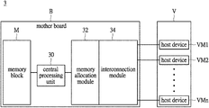
- FIG. 3 a memory management system of an embodiment of the instant disclosure is shown in a block diagram form.
- the memory management system 3 in this embodiment is mainly used to help the central processing unit 30 of a server to do memory management for a device system V.
- a memory block M is connected to the central processing unit 30 on the mother board B.
- the memory block is also the Double Data Rate Synchronous Dynamic Random Access Memory (DDR SDRAM), and the number of the host devices configured in the device system V, which is “n”, is determined based on the requirement and needs of different clients.
- DDR SDRAM Double Data Rate Synchronous Dynamic Random Access Memory
- the memory management system 3 comprises a memory allocation module 32 and an interconnection module 34 .
- the memory allocation module 32 and the interconnection module 34 are directly configured on the mother board B of a server.
- the interconnection module 34 can be the Peripheral Component Interconnect Express (PCI-E) bus, the Signal Root I/O Virtualization (SRIOV) bus or the Multi Root I/O Virtualization (MRIOV) bus.
- the interconnection module 34 is implemented by the Signal Root I/O Virtualization (SRIOV) bus.
- the memory allocation module 32 can be implemented by a Field-Programmable Gate Array (FPGA) chip, for example.
- the FPGA chip is reprogrammable, so that the instant disclosure can provide a customized memory management system for a client.
- the implementation of the present disclosure is not limited to the examples above.
- the memory allocation module 32 may be implemented by an integrated circuit (IC) chip, which may be an application-specific integrated circuit (ASIC) chip, or a dedicated chip, and so on.
- IC integrated circuit
- the memory allocation module 32 By programming the memory allocation module 32 (e.g., a FPGA chip), the number of the host devices VM 1 , VM 2 , . . . , VMn in the device system V can be determined. After that, according to the requirement and needs of a general client or an enterprise client, the memory allocation module 32 determines the memory capacity of the memory block, and divides the memory block to a plurality of memory sub-blocks (not shown). Finally, again by programming the memory allocation module 32 , the memory capacity of the memory sub-block that each host device VM 1 , VM 2 , . . . , VMn is allowed to use can be determined, and then an allocation table can be accordingly built. This allocation table records the relationship between the corresponding device code of each host device and the memory allocated to each host device, but the details relevant to the allocation table are omitted herein because they have been described in the last embodiment and FIG. 2 .
- This allocation table records the relationship between the corresponding device code of each host device and the memory
- this host device When a user operates one host device VM 1 , VM 2 , . . . , VMn configured in the device system V, this host device requests the central processing unit for accessing data. After recognizing the device code of the host device, the central processing unit responds to the host device according to the allocation table and the recognized device code.
- the response from the central processing unit is to allow the host devices to use one of the memory sub-blocks (not shown) for accessing data, and particularly the memory capacity of the memory sub-block the host device is allowed to use is determined according to the allocation table.
- the memory capacity of the memory sub-blocks may be all different, or some of the memory sub-blocks may have the same memory capacity.
- different device codes may be corresponded to the memory sub-blocks that have the same memory capacity.
- the memory that is allocated to each host device VM 1 , VM 2 , . . . , VMn must be equal to the memory capacity of one of the memory sub-blocks. Therefore, how to divide the memory block to a plurality of memory sub-blocks is determined by the memory that each host device VM 1 , VM 2 , . . . , VMn needs to do its work or can be allowed to use.
- the device system in this embodiment can be a physical device system or a virtual device system.
- the memory management system provided by this embodiment can do the memory management for a virtual device system having a plurality of virtual devices.
- the virtual device refers to the so-called Virtual Machine (VM).
- VM Virtual Machine
- the instant disclosure can provide a customized memory management system and a corresponding memory management method, such that the memory resource can be simply and efficiently allocated to each virtual machine in the virtual device system used by every client.
- the implementation of the present disclosure is not limited to the examples above.
- the memory management method and the memory management system provided by the above embodiment of the instant disclosure can help a central processing unit of a server to do memory management for a device system linked to the server.
- the memory management method and the memory management system provided by the above embodiment of the instant disclosure can be customized by the requirements and needs of clients.
- the memory management system provided by the instant disclosure can be directly configured on the mother board of a server. Therefore, as long as a customized memory management system is directly configured on the mother board of a client server, the client can have its own memory management system to do memory management for host devices that are responsible for different work.
- the implementation of the present disclosure is not limited to the examples above.
- the device system V can be a physical device system, each host device of which is a physical host device, for example, including a processing unit, or including a processing unit and a memory coupled to the processing unit.
- the memory management system 3 in FIG. 3 performs memory management for a physical device system including a plurality of physical host devices (indicated by symbols VM 1 , VM 2 , . . . , VMn) configured in the physical device system, wherein “n” is a positive integer.
- the memory block M is electrically coupled or connected to the central processing unit 30 .
- the memory block M may indicate one or more memory units as main or primary memory for use by the physical host devices.
- the memory block M may be DRAM-based volatile memory, such as based on Double Data Rate Synchronous Dynamic Random Access Memory (DDR SDRAM), for a specific generation, such as DDR, DDR2, DDR3, DDR4, or DDR5 and so on.
- DDR SDRAM Double Data Rate Synchronous Dynamic Random Access Memory
- the memory management system 3 in FIG. 3 inherently is capable of facilitating memory expansion for pooled computing resource in a resource pooling architecture based on the use of one or more resource pools.
- a pooled rack sever system can be implemented in accordance with the resource pooling architecture which is different from the traditional rack server.
- the pooled rack sever system is implemented by separating different corresponding devices into several pooled groups (e.g., GPU pool, power device pool, storage pool, and I/O pool) that can be expanded and the user is able to manage every group individually, as compared with the traditional sever based on a conventional computer which is built with a dedicated CPU, primary memory, power, I/O, GPU and HDD and so on, and cannot be extended in accordance with user's or practical requirements.
- a memory management or device can be implemented, based on that of FIG.
- computing pools e.g., CPU and/or GPU pools
- a computing and memory pool e.g., CPU and/or GPU pools, with memory
- a memory management system of another embodiment of the present disclosure is illustrated in a schematic block diagram form.
- a memory management system 100 based on that of FIG. 3 , is used for performing memory management for a device system DS so as to utilize memory resource of a memory system MS.
- the device system DS serves as a computing pool including a plurality of host devices D 1 , D 2 , . . . , Dn, each of which is a physical host device, for example, including a processing unit, or including a processing unit and a memory coupled to the processing unit.
- the memory system MS is a memory pool as main or primary memory for use by the host devices D 1 , D 2 , . . .
- the memory system MS may including a plurality of memory units 21 , for example, DRAM-based volatile memory, such as based on Double Data Rate Synchronous Dynamic Random Access Memory (DDR SDRAM), for a specific generation, such as DDR, DDR2, DDR3, DDR4, or DDR5 and so on.
- DDR SDRAM Double Data Rate Synchronous Dynamic Random Access Memory
- the memory management system 100 includes a central processing unit 130 , a memory allocation module 132 , and an interconnection module 134 , which may be implemented based on any one of the embodiments as illustrated in FIG. 1, 2 or 3 .
- the central processing unit 130 is coupled to the memory system MS and coupled to the host devices D 1 , D 2 , . . . , Dn by way of the memory allocation module 132 and an interconnection module 134 .
- the central processing unit 130 may be implemented by performing any one of the embodiments of the central processing unit 30 .
- the memory management system 100 serves as a role of efficient resource allocation so as to facilitate the implementation of a pooled rack server system based on a resource pooling architecture with respect to a computing pool (e.g., the device system DS) and a memory pool (e.g., the memory system MS). Because the memory system MS is used as main or primary memory for the device system DS, the memory management system 100 employs the memory allocation module 132 , which may be implemented based on any one of the embodiments of the memory allocation module 32 , to perform memory allocation with the benefit of hardware performance of computing.
- the memory allocation module 132 may be implemented by an integrated circuit (IC) chip, for example, a programmable chip, such as a field-programmable gate array (FPGA) chip, an application-specific integrated circuit (ASIC) chip, or a dedicated chip, and so on, wherein the IC chip includes hardware computing components for performance acceleration.
- the memory management system 100 employs the interconnection module 134 , which may be implemented based on any one of the embodiments of the interconnection module 34 , to perform interconnection to the device system DS.
- the interconnection module 134 may be implemented by using a circuit module for connection and signaling for Peripheral Component Interconnect Express (PCI-E) bus (e.g., generation 3th, 4 th , and so on), the Signal Root I/O Virtualization (SRIOV) bus, the Multi Root I/O Virtualization (MRIOV) bus, or a Signal Root I/O Virtualization (SRIOV) bus.
- PCI-E Peripheral Component Interconnect Express
- SRIOV Signal Root I/O Virtualization
- MRIOV Multi Root I/O Virtualization
- SRIOV Signal Root I/O Virtualization
- the central processing unit 130 and the memory allocation module 132 may be integrated and implemented by an integrated circuit so as to make the memory management system 100 more compact in size.
- the memory management system 100 in FIG. 4 can facilitate the implementation of a pooled rack server system based on a resource pooling architecture, as will be illustrated in the following.
- FIG. 5 an implementation of a pooled rack server system based on a resource pooling architecture is introduced in FIG. 5 , by disaggregating processors, memory, storage devices, and networking resources of a plurality of conventional servers into respective resource pools.
- a memory management device can be implemented based on the memory management system 100 to facilitate primary memory expansion for a computing and memory pool in an implementation of a pooled rack server system based on a resource pooling architecture.
- FIG. 5 an implementation of a pooled rack server system based on a resource pooling architecture is illustrated according to an embodiment. In FIG.
- a pooled rack server system 500 includes a plurality of resource pools, for examples, a computing and memory pool 510 , a storage pool 530 , and an input/output pool 540 .
- the computing and memory pool 510 includes a plurality of host devices (for example, processing units) D 1 , D 2 , . . . , Dn and a plurality of memory units indicated by MU 1 , MU 2 , . . .
- each of the host devices e.g., a processing unit
- the host devices are disposed on a circuit board and electrically coupled to an interface or bus, such as PCI-E bus, and the memory units MU 1 to MUp are also disposed on the circuit board, for example, through respective memory sockets (not shown, for sake's of brevity), and electrically coupled to a common interface or bus, such as PCI-E bus or an internal bus, for communicatively being coupled to the associated host devices.
- the storage pool 530 is used for secondary memory where programs and data are kept on a long-term basis, for example, for possible future use or for record-keeping purposes, and often for data backup or storage.
- the storage pool 530 includes a plurality of storage units SU, such as solid-state devices (SSD) or hard disk drives (HDD).
- the input/output pool 540 includes a plurality of input/output (I/O) units IU for providing I/O interconnections (e.g., networking interconnections).
- I/O interconnections e.g., networking interconnections.
- the pooled rack server system 500 may include another resource pool, such as a power device pool 550 (e.g., AC to DC and/or DC to DC power adaptors and so on) for powering the above resource pools (such as 530 , 540 and so on) with heat dissipation.
- a power device pool 550 e.g., AC to DC and/or DC to DC power adaptors and so on
- the pooled rack server system 500 is an implementation of a resource pooling architecture by disaggregating processors storage, memory, and networking resources of a plurality of conventional servers, a datacenter administrator can then flexibly assign those resources to meet the demands of individual workloads.
- This resource pooling architecture brings flexible deployment, component redundancy capability, better resource utilization, so as to reduce the total operational expenditures.
- a memory management device 200 implemented based on the memory management system 100 in FIG. 4 can be employed (e.g., by connection to the computing and memory pool 510 ) to facilitate primary memory expansion.
- a memory pool 520 including a plurality of memory units XMU 1 to XMUq can be added to (e.g., mounted in) the pooled rack server system 500 and is coupled to the computing and memory pool 510 through the memory management device 200 . Since the memory management device 200 has the benefit of efficient resource allocation due to its implementation based on the memory management system 100 in FIG. 5 , the computing and memory pool 510 is allowed to further utilize the memory resource of the memory pool 520 as expanded main or primary memory, thus preventing the issues of latency between processing unit and memory.
- a memory management device can be implemented based on the memory management system 100 to facilitate a primary memory pool and a computing pool in another implementation of a resource pooling architecture of a pooled rack server system in which the computing and memory pool 510 in FIG. 5 is replaced with a computing pool including a plurality of host devices (for example, processing units) D 1 , D 2 , . . . , Dn, and the memory pool 520 can serve as a primary memory pool.
- host devices for example, processing units
- the computing and memory pool 510 in FIG. 5 is required to be upgraded for performance enhancement, for example, by substituting a new computing and memory pool that employs processors and/or memory of upgraded technology for the current computing and memory pool, there are various approaches to physical memory resource usage due to the utilization of the memory management device 200 .
- the memory pool 520 can still be utilized in the pooled rack server system 500 and can be coupled to the new computing and memory pool (or new computing pool) through the memory management device 200 .
- the memory units of the computing and memory pool 510 are memory modules (e.g., DDR4 (or DDR5) dual in-line memory module (DIMM)) which (e.g., in specification) outperform the memory units (e.g., DDR3 DIMM) of the memory pool 520 , the memory units of the previous computing and memory pool 510 can be reused by the replacement of the memory units of the memory pool 520 with the memory units (e.g., through corresponding memory sockets) detached from the previous computing and memory pool 510 (e.g., through corresponding memory sockets), in addition to the substitution.
- DDR4 or DDR5 dual in-line memory module (DIMM)
- DIMM dual in-line memory module
- the memory units of the previous computing and memory pool 510 can be reused by the insertion of the memory units detached from the previous computing and memory pool 510 (e.g., through corresponding memory sockets) into the new computing and memory pool, in addition to the substitution.
- the memory management device 200 has the benefit of efficient resource allocation due to its implementation based on the memory management system 100 in FIG. 4 , the computing and memory pool 510 is allowed to utilize the memory resource of the memory pool 520 as main or primary memory, thus preventing the issues of wasting resources, latency between processing unit and memory and also saving hardware resource and cost. In this manner, the memory management device 200 as illustrated in FIG. 5 can also save the hardware resource and facilitate the utilization and flexible deployment of the memory resource.
- the technical effects of efficient resource allocation provided by the memory management device 200 in the above embodiments are different from the storage expansion functionality of the conventional storage device (such as solid-state devices (SSD), hard disk drives (HDD).
- the storage expansion functionality of the conventional storage device (such as SSD, HDD) merely needs an adapter for implementation of data conversion between the host device and memory of the storage device.
- the memory management device used in the above embodiments for the primary memory expansion or primary memory requires the efficient resource allocation provided by the memory management system in FIG. 4 so as to fulfil the computing performance requirements of CPU and memory data access.
- the central processing unit 130 efficiently handles the request from the host devices and the memory allocation module 132 performs memory allocation, and the interconnection module 134 is configured to provide effective and efficient linking to the host devices, thus achieving the technical effects of efficient memory allocation and facilitating primary memory expansion in the implementation of a pooled rack server system based on the resource pooling architecture.
- a memory management or device can be implemented, based on that of FIG. 3 , to facilitate expansion of primary memory resource for computing pools (e.g., CPU and/or GPU pools) and a computing and memory pool (e.g., CPU and/or GPU pools, with memory) so that a new primary memory resource can be utilized in the pooled rack sever system when additional primary memory resource is required, thereby enhancing system performance.
- computing pools e.g., CPU and/or GPU pools
- a computing and memory pool e.g., CPU and/or GPU pools, with memory
Landscapes
- Engineering & Computer Science (AREA)
- Theoretical Computer Science (AREA)
- General Engineering & Computer Science (AREA)
- Physics & Mathematics (AREA)
- General Physics & Mathematics (AREA)
- Human Computer Interaction (AREA)
- Computer Hardware Design (AREA)
- Information Retrieval, Db Structures And Fs Structures Therefor (AREA)
Abstract
Description
Claims (10)
Priority Applications (1)
| Application Number | Priority Date | Filing Date | Title |
|---|---|---|---|
| US16/812,580 US11216194B2 (en) | 2016-10-19 | 2020-03-09 | Memory management system and method thereof |
Applications Claiming Priority (2)
| Application Number | Priority Date | Filing Date | Title |
|---|---|---|---|
| US15/297,745 US20180107392A1 (en) | 2016-10-19 | 2016-10-19 | Memory management system and method thereof |
| US16/812,580 US11216194B2 (en) | 2016-10-19 | 2020-03-09 | Memory management system and method thereof |
Related Parent Applications (1)
| Application Number | Title | Priority Date | Filing Date |
|---|---|---|---|
| US15/297,745 Continuation-In-Part US20180107392A1 (en) | 2016-10-19 | 2016-10-19 | Memory management system and method thereof |
Publications (2)
| Publication Number | Publication Date |
|---|---|
| US20200210081A1 US20200210081A1 (en) | 2020-07-02 |
| US11216194B2 true US11216194B2 (en) | 2022-01-04 |
Family
ID=71123036
Family Applications (1)
| Application Number | Title | Priority Date | Filing Date |
|---|---|---|---|
| US16/812,580 Active US11216194B2 (en) | 2016-10-19 | 2020-03-09 | Memory management system and method thereof |
Country Status (1)
| Country | Link |
|---|---|
| US (1) | US11216194B2 (en) |
Families Citing this family (1)
| Publication number | Priority date | Publication date | Assignee | Title |
|---|---|---|---|---|
| US12050807B2 (en) * | 2021-04-23 | 2024-07-30 | EMC IP Holding Company, LLC | Memory management system and method |
Citations (7)
| Publication number | Priority date | Publication date | Assignee | Title |
|---|---|---|---|---|
| US20090319604A1 (en) | 2008-06-19 | 2009-12-24 | Keisuke Hatasaki | Computing system and method of changing i/o configuration thereof |
| US8161161B2 (en) | 2005-10-31 | 2012-04-17 | Sony Computer Entertainment, Inc. | Information processing method and information processing apparatus |
| US20130159622A1 (en) | 2010-06-18 | 2013-06-20 | Lsi Corporation | Chained, scalable storage devices |
| US20160274814A1 (en) | 2014-09-15 | 2016-09-22 | Intel Corporation | Memory management in virtualized computing |
| US20170031593A1 (en) | 2015-07-29 | 2017-02-02 | Red Hat Israel, Ltd. | Maintaining guest input/output tables in swappable memory |
| US20170337007A1 (en) | 2015-09-25 | 2017-11-23 | Stmicroelectronics (Rousset) Sas | Non-volatile memory device having a memory size |
| US20180192540A1 (en) * | 2016-12-30 | 2018-07-05 | Mohan J. Kumar | Mechanisms for sas-free cabling in rack scale design |
-
2020
- 2020-03-09 US US16/812,580 patent/US11216194B2/en active Active
Patent Citations (7)
| Publication number | Priority date | Publication date | Assignee | Title |
|---|---|---|---|---|
| US8161161B2 (en) | 2005-10-31 | 2012-04-17 | Sony Computer Entertainment, Inc. | Information processing method and information processing apparatus |
| US20090319604A1 (en) | 2008-06-19 | 2009-12-24 | Keisuke Hatasaki | Computing system and method of changing i/o configuration thereof |
| US20130159622A1 (en) | 2010-06-18 | 2013-06-20 | Lsi Corporation | Chained, scalable storage devices |
| US20160274814A1 (en) | 2014-09-15 | 2016-09-22 | Intel Corporation | Memory management in virtualized computing |
| US20170031593A1 (en) | 2015-07-29 | 2017-02-02 | Red Hat Israel, Ltd. | Maintaining guest input/output tables in swappable memory |
| US20170337007A1 (en) | 2015-09-25 | 2017-11-23 | Stmicroelectronics (Rousset) Sas | Non-volatile memory device having a memory size |
| US20180192540A1 (en) * | 2016-12-30 | 2018-07-05 | Mohan J. Kumar | Mechanisms for sas-free cabling in rack scale design |
Non-Patent Citations (4)
| Title |
|---|
| Final Office Action dated Oct. 18, 2018 for U.S. Appl. No. 15/297,745 (parent application). |
| Final Office Action dated Oct. 9, 2019 for U.S. Appl. No. 15/297,745 (parent application). |
| Non-Final Office Action dated Feb. 26, 2019 for U.S. Appl. No. 15/297,745 (parent application). |
| Non-Final Office Action dated Mar. 28, 2018 for U.S. Appl. No. 15/297,745 (parent application). |
Also Published As
| Publication number | Publication date |
|---|---|
| US20200210081A1 (en) | 2020-07-02 |
Similar Documents
| Publication | Publication Date | Title |
|---|---|---|
| US10372639B2 (en) | System and method to avoid SMBus address conflicts via a baseboard management controller | |
| US11775464B2 (en) | Computer system and a computer device | |
| US10592285B2 (en) | System and method for information handling system input/output resource management | |
| US7783807B2 (en) | Controlling resource transfers in a logically partitioned computer system | |
| CN103188091A (en) | Management method of cloud service system and management system | |
| CN114747190B (en) | Computer-implemented method, system and storage medium | |
| US9755986B1 (en) | Techniques for tightly-integrating an enterprise storage array into a distributed virtualized computing environment | |
| US10877918B2 (en) | System and method for I/O aware processor configuration | |
| TW202011146A (en) | A method and system for dynamically allocating and optimizing power resources, and non-transitory machine-readable medium | |
| US11216194B2 (en) | Memory management system and method thereof | |
| US20180048559A1 (en) | Apparatus assigning controller and apparatus assigning method | |
| US9830078B2 (en) | System and method for pre-operating system memory map management to minimize operating system failures | |
| US8230260B2 (en) | Method and system for performing parallel computer tasks | |
| US10838867B2 (en) | System and method for amalgamating server storage cache memory | |
| US11860783B2 (en) | Direct swap caching with noisy neighbor mitigation and dynamic address range assignment | |
| TW201328246A (en) | Method and system for managing cloud server system | |
| US20200226044A1 (en) | Memory system and data processing system | |
| US20220011968A1 (en) | Mapping of raid-cli requests to vsan commands by an out-of-band management platform using nlp | |
| WO2023172319A1 (en) | Direct swap caching with noisy neighbor mitigation and dynamic address range assignment | |
| US20180107392A1 (en) | Memory management system and method thereof | |
| WO2023140911A1 (en) | Systems and methods with integrated memory pooling and direct swap caching | |
| JP2011145783A (en) | Computer system | |
| EP3695319A1 (en) | Method and reallocation component for managing reallocation of information from source to target memory sled |
Legal Events
| Date | Code | Title | Description |
|---|---|---|---|
| AS | Assignment |
Owner name: ALIANE TECHNOLOGIES CORPORATION, TAIWAN Free format text: ASSIGNMENT OF ASSIGNORS INTEREST;ASSIGNORS:HU, CHIA-CHEN;CHEN, HUAI-EN;REEL/FRAME:052051/0399 Effective date: 20200121 |
|
| FEPP | Fee payment procedure |
Free format text: ENTITY STATUS SET TO UNDISCOUNTED (ORIGINAL EVENT CODE: BIG.); ENTITY STATUS OF PATENT OWNER: SMALL ENTITY |
|
| FEPP | Fee payment procedure |
Free format text: ENTITY STATUS SET TO SMALL (ORIGINAL EVENT CODE: SMAL); ENTITY STATUS OF PATENT OWNER: SMALL ENTITY |
|
| STPP | Information on status: patent application and granting procedure in general |
Free format text: DOCKETED NEW CASE - READY FOR EXAMINATION |
|
| STPP | Information on status: patent application and granting procedure in general |
Free format text: NON FINAL ACTION MAILED |
|
| STPP | Information on status: patent application and granting procedure in general |
Free format text: RESPONSE TO NON-FINAL OFFICE ACTION ENTERED AND FORWARDED TO EXAMINER |
|
| STPP | Information on status: patent application and granting procedure in general |
Free format text: FINAL REJECTION MAILED |
|
| STPP | Information on status: patent application and granting procedure in general |
Free format text: DOCKETED NEW CASE - READY FOR EXAMINATION |
|
| STPP | Information on status: patent application and granting procedure in general |
Free format text: NOTICE OF ALLOWANCE MAILED -- APPLICATION RECEIVED IN OFFICE OF PUBLICATIONS |
|
| STPP | Information on status: patent application and granting procedure in general |
Free format text: PUBLICATIONS -- ISSUE FEE PAYMENT RECEIVED |
|
| STPP | Information on status: patent application and granting procedure in general |
Free format text: PUBLICATIONS -- ISSUE FEE PAYMENT VERIFIED |
|
| STCF | Information on status: patent grant |
Free format text: PATENTED CASE |