US11216115B2 - Electronic device and method for controlling touch sensing signals and storage medium - Google Patents
Electronic device and method for controlling touch sensing signals and storage medium Download PDFInfo
- Publication number
- US11216115B2 US11216115B2 US16/104,138 US201816104138A US11216115B2 US 11216115 B2 US11216115 B2 US 11216115B2 US 201816104138 A US201816104138 A US 201816104138A US 11216115 B2 US11216115 B2 US 11216115B2
- Authority
- US
- United States
- Prior art keywords
- capacitive sensing
- sensing scheme
- conductive lines
- electronic device
- operation mode
- Prior art date
- Legal status (The legal status is an assumption and is not a legal conclusion. Google has not performed a legal analysis and makes no representation as to the accuracy of the status listed.)
- Active, expires
Links
Images


Classifications
-
- G—PHYSICS
- G06—COMPUTING; CALCULATING OR COUNTING
- G06F—ELECTRIC DIGITAL DATA PROCESSING
- G06F3/00—Input arrangements for transferring data to be processed into a form capable of being handled by the computer; Output arrangements for transferring data from processing unit to output unit, e.g. interface arrangements
- G06F3/01—Input arrangements or combined input and output arrangements for interaction between user and computer
- G06F3/03—Arrangements for converting the position or the displacement of a member into a coded form
- G06F3/041—Digitisers, e.g. for touch screens or touch pads, characterised by the transducing means
- G06F3/0416—Control or interface arrangements specially adapted for digitisers
- G06F3/0418—Control or interface arrangements specially adapted for digitisers for error correction or compensation, e.g. based on parallax, calibration or alignment
- G06F3/04184—Synchronisation with the driving of the display or the backlighting unit to avoid interferences generated internally
-
- G—PHYSICS
- G06—COMPUTING; CALCULATING OR COUNTING
- G06F—ELECTRIC DIGITAL DATA PROCESSING
- G06F3/00—Input arrangements for transferring data to be processed into a form capable of being handled by the computer; Output arrangements for transferring data from processing unit to output unit, e.g. interface arrangements
- G06F3/01—Input arrangements or combined input and output arrangements for interaction between user and computer
- G06F3/03—Arrangements for converting the position or the displacement of a member into a coded form
- G06F3/041—Digitisers, e.g. for touch screens or touch pads, characterised by the transducing means
- G06F3/0412—Digitisers structurally integrated in a display
-
- G—PHYSICS
- G06—COMPUTING; CALCULATING OR COUNTING
- G06F—ELECTRIC DIGITAL DATA PROCESSING
- G06F3/00—Input arrangements for transferring data to be processed into a form capable of being handled by the computer; Output arrangements for transferring data from processing unit to output unit, e.g. interface arrangements
- G06F3/01—Input arrangements or combined input and output arrangements for interaction between user and computer
- G06F3/03—Arrangements for converting the position or the displacement of a member into a coded form
- G06F3/041—Digitisers, e.g. for touch screens or touch pads, characterised by the transducing means
- G06F3/0414—Digitisers, e.g. for touch screens or touch pads, characterised by the transducing means using force sensing means to determine a position
-
- G—PHYSICS
- G06—COMPUTING; CALCULATING OR COUNTING
- G06F—ELECTRIC DIGITAL DATA PROCESSING
- G06F3/00—Input arrangements for transferring data to be processed into a form capable of being handled by the computer; Output arrangements for transferring data from processing unit to output unit, e.g. interface arrangements
- G06F3/01—Input arrangements or combined input and output arrangements for interaction between user and computer
- G06F3/03—Arrangements for converting the position or the displacement of a member into a coded form
- G06F3/041—Digitisers, e.g. for touch screens or touch pads, characterised by the transducing means
- G06F3/0416—Control or interface arrangements specially adapted for digitisers
- G06F3/04166—Details of scanning methods, e.g. sampling time, grouping of sub areas or time sharing with display driving
- G06F3/041662—Details of scanning methods, e.g. sampling time, grouping of sub areas or time sharing with display driving using alternate mutual and self-capacitive scanning
-
- G—PHYSICS
- G06—COMPUTING; CALCULATING OR COUNTING
- G06F—ELECTRIC DIGITAL DATA PROCESSING
- G06F3/00—Input arrangements for transferring data to be processed into a form capable of being handled by the computer; Output arrangements for transferring data from processing unit to output unit, e.g. interface arrangements
- G06F3/01—Input arrangements or combined input and output arrangements for interaction between user and computer
- G06F3/03—Arrangements for converting the position or the displacement of a member into a coded form
- G06F3/041—Digitisers, e.g. for touch screens or touch pads, characterised by the transducing means
- G06F3/044—Digitisers, e.g. for touch screens or touch pads, characterised by the transducing means by capacitive means
- G06F3/0446—Digitisers, e.g. for touch screens or touch pads, characterised by the transducing means by capacitive means using a grid-like structure of electrodes in at least two directions, e.g. using row and column electrodes
-
- G—PHYSICS
- G06—COMPUTING; CALCULATING OR COUNTING
- G06F—ELECTRIC DIGITAL DATA PROCESSING
- G06F3/00—Input arrangements for transferring data to be processed into a form capable of being handled by the computer; Output arrangements for transferring data from processing unit to output unit, e.g. interface arrangements
- G06F3/01—Input arrangements or combined input and output arrangements for interaction between user and computer
- G06F3/048—Interaction techniques based on graphical user interfaces [GUI]
- G06F3/0487—Interaction techniques based on graphical user interfaces [GUI] using specific features provided by the input device, e.g. functions controlled by the rotation of a mouse with dual sensing arrangements, or of the nature of the input device, e.g. tap gestures based on pressure sensed by a digitiser
- G06F3/0488—Interaction techniques based on graphical user interfaces [GUI] using specific features provided by the input device, e.g. functions controlled by the rotation of a mouse with dual sensing arrangements, or of the nature of the input device, e.g. tap gestures based on pressure sensed by a digitiser using a touch-screen or digitiser, e.g. input of commands through traced gestures
-
- G—PHYSICS
- G06—COMPUTING; CALCULATING OR COUNTING
- G06F—ELECTRIC DIGITAL DATA PROCESSING
- G06F2203/00—Indexing scheme relating to G06F3/00 - G06F3/048
- G06F2203/041—Indexing scheme relating to G06F3/041 - G06F3/045
- G06F2203/04104—Multi-touch detection in digitiser, i.e. details about the simultaneous detection of a plurality of touching locations, e.g. multiple fingers or pen and finger
-
- G—PHYSICS
- G06—COMPUTING; CALCULATING OR COUNTING
- G06F—ELECTRIC DIGITAL DATA PROCESSING
- G06F2203/00—Indexing scheme relating to G06F3/00 - G06F3/048
- G06F2203/041—Indexing scheme relating to G06F3/041 - G06F3/045
- G06F2203/04105—Pressure sensors for measuring the pressure or force exerted on the touch surface without providing the touch position
-
- G—PHYSICS
- G06—COMPUTING; CALCULATING OR COUNTING
- G06F—ELECTRIC DIGITAL DATA PROCESSING
- G06F2203/00—Indexing scheme relating to G06F3/00 - G06F3/048
- G06F2203/041—Indexing scheme relating to G06F3/041 - G06F3/045
- G06F2203/04108—Touchless 2D- digitiser, i.e. digitiser detecting the X/Y position of the input means, finger or stylus, also when it does not touch, but is proximate to the digitiser's interaction surface without distance measurement in the Z direction
-
- H—ELECTRICITY
- H04—ELECTRIC COMMUNICATION TECHNIQUE
- H04M—TELEPHONIC COMMUNICATION
- H04M1/00—Substation equipment, e.g. for use by subscribers
- H04M1/02—Constructional features of telephone sets
- H04M1/0202—Portable telephone sets, e.g. cordless phones, mobile phones or bar type handsets
- H04M1/026—Details of the structure or mounting of specific components
- H04M1/0266—Details of the structure or mounting of specific components for a display module assembly
-
- H—ELECTRICITY
- H04—ELECTRIC COMMUNICATION TECHNIQUE
- H04M—TELEPHONIC COMMUNICATION
- H04M2250/00—Details of telephonic subscriber devices
- H04M2250/12—Details of telephonic subscriber devices including a sensor for measuring a physical value, e.g. temperature or motion
-
- H—ELECTRICITY
- H04—ELECTRIC COMMUNICATION TECHNIQUE
- H04M—TELEPHONIC COMMUNICATION
- H04M2250/00—Details of telephonic subscriber devices
- H04M2250/22—Details of telephonic subscriber devices including a touch pad, a touch sensor or a touch detector
Definitions
- Various embodiments relate to touch circuitry and electronic devices having the same.
- An electronic device may include at least one display.
- the user may control the electronic device through an input device while viewing various operational states of the electronic device or application operations through the display.
- Portable electronic devices e.g., smartphones, may have an input device (e.g., a touchscreen) capable of receiving users' touch inputs to the screen and provide user interfaces.
- Electronic devices with capacitive touch circuitry may be subject to occurrence of unintended capacitance between a touch sensor and a display panel, and the electronic devices may cause noise upon operation according to self- and/or mutual capacitance sensing type.
- the capacitance between the touch sensor and the display panel varies, creating noise.
- an electronic device may control touch sensing signals, reducing or removing noise.
- an electronic device may comprise a housing including a first plate and a second plate positioned opposite the first plate, a display positioned between the first plate and the second plate, a touch sensing panel positioned between the display and the first plate, spaced apart from the display by an air gap, and including a plurality of first conductive lines extending in a first direction and a plurality of second conductive lines extending in a different direction from the first direction as viewed from the first plate and crossing the plurality of first conductive lines, a wireless communication circuit, at least one processor functionally connected with the display, the panel, and the wireless communication circuit, and a memory functionally connected with the processor, wherein the memory may store instructions executed to enable the processor to detect an external object above or near the first plate; in a first operation, alternately use a first detection scheme and a second detection scheme, the first detection scheme detecting, independently, variations in capacitances of the plurality of first conductive lines and the plurality of second conductive lines during a first time period, and the second detection scheme
- touch circuitry may include a touch sensor and a control circuit electrically connected with the touch sensor.
- the control circuit may be configured to provide a first driving signal to the touch sensor in a first operation mode, detect a first event related to mode switching, and provide a second driving signal different from the first driving signal to the touch sensor in a second operation mode based on detecting the first event.
- an electronic device may comprise a housing and touch circuitry mounted inside the housing or at least partially disposed inside the housing and configured to detect a touch or hovering.
- the touch circuitry may be configured to operate in a first operation mode and according to a first driving signal, detect a first event related to mode switching, and operate in a second operation mode and according to a second driving signal different from the first driving signal based on detecting the first event.
- a method for operating an electronic device may comprise operating touch circuitry configured to detect a touch or hovering according to a first driving signal in a first operation mode, detecting a first event related to mode switching, and operating the touch circuitry according to a second driving signal different from the first driving signal in a second operation mode based on detecting the first event.
- various functions described below can be implemented or supported by one or more computer programs, each of which is formed from computer readable program code and embodied in a computer readable medium.
- application and “program” refer to one or more computer programs, software components, sets of instructions, procedures, functions, objects, classes, instances, related data, or a portion thereof adapted for implementation in a suitable computer readable program code.
- computer readable program code includes any type of computer code, including source code, object code, and executable code.
- computer readable medium includes any type of medium capable of being accessed by a computer, such as read only memory (ROM), random access memory (RAM), a hard disk drive, a compact disc (CD), a digital video disc (DVD), or any other type of memory.
- ROM read only memory
- RAM random access memory
- CD compact disc
- DVD digital video disc
- a “non-transitory” computer readable medium excludes wired, wireless, optical, or other communication links that transport transitory electrical or other signals.
- a non-transitory computer readable medium includes media where data can be permanently stored and media where data can be stored and later overwritten, such as a rewritable optical disc or an erasable memory device.
- FIG. 1 is a view illustrating an electronic device in a network environment according to an embodiment
- FIG. 2 is a block diagram illustrating a display device according to an embodiment
- FIG. 3A is a perspective view illustrating an electronic device according to an embodiment
- FIG. 3B is a perspective view illustrating an electronic device as viewed in a different direction
- FIGS. 4A and 4B are views illustrating a display according to an embodiment
- FIG. 5 is a block diagram illustrating an electronic device according to an embodiment
- FIG. 6 is a flowchart illustrating a method for changing modes of an electronic device according to an embodiment
- FIGS. 7A and 7B are views illustrating driving signals according to an embodiment
- FIGS. 8A-8C are views illustrating driving signals according to an embodiment
- FIGS. 9A-9D are views illustrating a method for operating an electronic device according to an embodiment
- FIG. 10 is a flowchart illustrating a method for changing modes of an electronic device according to an embodiment.
- FIG. 11 is a view illustrating a method for recognizing a palm touch on an electronic device according to an embodiment.
- FIGS. 1 through 11 discussed below, and the various embodiments used to describe the principles of the present disclosure in this patent document are by way of illustration only and should not be construed in any way to limit the scope of the disclosure. Those skilled in the art will understand that the principles of the present disclosure may be implemented in any suitably arranged system or device.
- FIG. 1 is a block diagram illustrating an electronic device 101 in a network environment 100 according to various embodiments.
- the electronic device 101 in the network environment 100 may communicate with an electronic device 102 via a first network 198 (e.g., a short-range wireless communication network), or an electronic device 104 or a server 108 via a second network 199 (e.g., a long-range wireless communication network).
- the electronic device 101 may communicate with the electronic device 104 via the server 108 .
- the electronic device 101 may include a processor 120 , a memory 130 , an input device 150 , a sound output device 155 , a display device 160 , an audio module 170 , a sensor module 176 , an interface 177 , a connecting terminal 178 , a haptic module 179 , a camera module 180 , a power management module 188 , a battery 189 , a communication module 190 , a subscriber identification module 196 , and an antenna module 197 .
- the electronic device 101 may exclude at least one (e.g., the display device 160 or the camera module 180 ) of the components or add other components.
- some components may be implemented to be integrated together, e.g., as if the sensor module 176 (e.g., a fingerprint sensor, an iris sensor, or an illuminance sensor) is embedded in the display device 160 (e.g., a display).
- the sensor module 176 e.g., a fingerprint sensor, an iris sensor, or an illuminance sensor
- the display device 160 e.g., a display
- the processor 120 may drive, e.g., software (e.g., a program 140 ) to control at least one other component (e.g., a hardware or software component) of the electronic device 101 connected with the processor 120 and may process or compute various data.
- the processor 120 may load and process a command or data received from another component (e.g., the sensor module 176 or the communication module 190 ) on a volatile memory 132 , and the processor 120 may store resultant data in a non-volatile memory 134 .
- the processor 120 may include a main processor 121 (e.g., a central processing unit (CPU) or an application processor), and additionally or alternatively, an auxiliary processor 123 (e.g., a graphics processing unit (GPU), an image signal processor, a sensor hub processor, or a communication processor) that is operated independently from the main processor 121 and that consumes less power than the main processor 121 or is specified for a designated function.
- auxiliary processor 123 may be operated separately from or embedded in the main processor 121 .
- the auxiliary processor 123 may control at least some (or at least a portion) of functions or states related to at least one (e.g., the display device 160 , the sensor module 176 , or the communication module 190 ) of the components of the electronic device 101 , instead of the main processor 121 while the main processor 121 is in an inactive (e.g., sleep) state or along with the main processor 121 while the main processor 121 is an active state (e.g., performing an application).
- the auxiliary processor 123 e.g., an image signal processor or a communication processor
- the memory 130 may store various data used by at least one component (e.g., the processor 120 ) of the electronic device 101 , e.g., software (e.g., the program 140 ) and input data or output data for a command related to the software.
- the memory 130 may include the volatile memory 132 or the non-volatile memory 134 .
- the program 140 may include, e.g., an operating system (OS) 142 , middleware 144 , or an application 146 .
- OS operating system
- middleware middleware
- application application
- the input device 150 may be a device for receiving a command or data, which is to be used for a component (e.g., the processor 120 ) of the electronic device 101 , from an outside (e.g., a user) of the electronic device 101 .
- the input device 150 may include, e.g., a microphone, a mouse, or a keyboard.
- the sound output device 155 may be a device for outputting sound signals to the outside of the electronic device 101 .
- the sound output device 155 may include, e.g., a speaker which is used for general purposes, such as playing multimedia or recording and playing, and a receiver used for call receiving purposes. According to an embodiment, the receiver may be formed integrally or separately from the speaker.
- the display 160 may be a device for visually providing information to a user of the electronic device 101 .
- the display device 160 may include, e.g., a display, a hologram device, or a projector and a control circuit for controlling the display, hologram device, or projector.
- the display device 160 may include touch circuitry or a pressure sensor capable of measuring the strength of a pressure for a touch.
- the audio module 170 may convert a sound into an electrical signal and vice versa. According to an embodiment, the audio module 170 may obtain a sound through the input device 150 or output a sound through the sound output device 155 or an external electronic device (e.g., an electronic device 102 (e.g., a speaker or a headphone) wiredly or wirelessly connected with the electronic device 101 .
- an electronic device 102 e.g., a speaker or a headphone
- the sensor module 176 may generate an electrical signal or data value corresponding to an internal operating state (e.g., power or temperature) or external environmental state of the electronic device 101 .
- the sensor module 176 may include, e.g., a gesture sensor, a gyro sensor, an atmospheric pressure sensor, a magnetic sensor, an acceleration sensor, a grip sensor, a proximity sensor, a color sensor, an infrared (IR) sensor, a bio sensor, a temperature sensor, a humidity sensor, or an illuminance sensor.
- the interface 177 may support a designated protocol enabling a wired or wireless connection with an external electronic device (e.g., the electronic device 102 ).
- the interface 177 may include a high definition multimedia interface (HDMI), a universal serial bus (USB) interface, a secure digital (SD) card interface, or an audio interface.
- HDMI high definition multimedia interface
- USB universal serial bus
- SD secure digital
- the connecting terminal 178 may include a connector, e.g., an HDMI connector, a USB connector, an SD card connector, or an audio connector (e.g., a headphone connector), which is able to physically connect the electronic device 101 with an external electronic device (e.g., the electronic device 102 ).
- a connector e.g., an HDMI connector, a USB connector, an SD card connector, or an audio connector (e.g., a headphone connector), which is able to physically connect the electronic device 101 with an external electronic device (e.g., the electronic device 102 ).
- the haptic module 179 may convert an electrical signal into a mechanical stimulus (e.g., a vibration or a movement) or electrical stimulus which may be recognized by a user via his tactile sensation or kinesthetic sensation.
- the haptic module 179 may include, e.g., a motor, a piezoelectric element, or an electric stimulator.
- the camera module 180 may capture a still image or moving images.
- the camera module 180 may include one or more lenses, an image sensor, an image signal processor, or a flash.
- the power management module 188 may be a module for managing power supplied to the electronic device 101 .
- the power management module 188 may be configured as at least part of, e.g., a power management integrated circuit (PMIC).
- PMIC power management integrated circuit
- the battery 189 may be a device for supplying power to at least one component of the electronic device 101 .
- the battery 189 may include, e.g., a primary cell which is not rechargeable, a secondary cell which is rechargeable, or a fuel cell.
- the communication module 190 may support establishing a wired or wireless communication channel between the electronic device 101 and an external electronic device (e.g., the electronic device 102 , the electronic device 104 , or the server 108 ) and performing communication through the established communication channel.
- the communication module 190 may include one or more communication processors that are operated independently from the processor 120 (e.g., an application processor) and supports wired or wireless communication.
- the communication module 190 may include a wireless communication module 192 (e.g., a cellular communication module, a short-range wireless communication module, or a global navigation satellite system (GNSS) communication module) or a wired communication module 194 (e.g., a local area network (LAN) communication module or a power line communication (PLC) module).
- a wireless communication module 192 e.g., a cellular communication module, a short-range wireless communication module, or a global navigation satellite system (GNSS) communication module
- GNSS global navigation satellite system
- wired communication module 194 e.g., a local area network (LAN) communication module or a power line communication (PLC) module.
- LAN local area network
- PLC power line communication
- a corresponding one of the wireless communication module 192 and the wired communication module 194 may be used to communicate with an external electronic device through a first network 198 (e.g., a short-range communication network, such as bluetooth, wireless-fidelity (Wi-Fi) direct, or infrared data association (IrDA)) or a second network 199 (e.g., a long-range communication network, such as a cellular network, the Internet, or a communication network (e.g., LAN or wide area network (WAN)).
- a short-range communication network such as bluetooth, wireless-fidelity (Wi-Fi) direct, or infrared data association (IrDA)
- a second network 199 e.g., a long-range communication network, such as a cellular network, the Internet, or a communication network (e.g., LAN or wide area network (WAN)
- the above-enumerated types of communication modules 190 may be implemented in a single chip or individually in separate chips.
- the wireless communication module 192 may differentiate and authenticate the electronic device 101 in the communication network using user information stored in the subscriber identification module 196 .
- the antenna module 197 may include one or more antennas for transmitting or receiving a signal or power to/from an outside.
- the communication module 190 e.g., the wireless communication module 192
- inter-peripheral communication scheme e.g., a bus, general purpose input/output (GPIO), serial peripheral interface (SPI), or mobile industry processor interface (MIPI)
- GPIO general purpose input/output
- SPI serial peripheral interface
- MIPI mobile industry processor interface
- commands or data may be transmitted or received between the electronic device 101 and the external electronic device 104 via the server 108 coupled with the second network 199 .
- Each of the electronic devices 102 and 104 may be a device of a same type as, or a different type, from the electronic device 101 .
- all or some of operations executed on the electronic device 101 may be run on one or more other external electronic devices.
- the electronic device 101 when the electronic device 101 should perform a certain function or service automatically or at a request, the electronic device 101 , instead of, or in addition to, executing the function or service on its own, may request an external electronic device to perform at least some functions associated therewith.
- the external electronic device may execute the requested functions or additional functions and transfer a result of the execution to the electronic device 101 .
- the electronic device 101 may provide a requested function or service by processing the received result as it is or additionally.
- a cloud computing, distributed computing, or client-server computing technique may be used, for example.
- FIG. 2 is a block diagram 200 illustrating the display device 160 according to various embodiments.
- the display device 160 may include a display 210 and a display driver integrated circuit (DDI) 230 to control the display 110 .
- the DDI 230 may include an interface module 231 , memory 233 (e.g., buffer memory), an image processing module 235 , or a mapping module 237 .
- the DDI 230 may receive image information that contains image data or an image control signal corresponding to a command for controlling the image data from the processor 120 (e.g., the main processor 121 (e.g., an application processor) or the auxiliary processor 123 operated independently from the function of the main processor 121 ) through, e.g., the interface module 231 .
- the DDI 230 may communicate, for example, with touch circuitry 250 or the sensor module 176 via the interface module 231 .
- the DDI 230 may also store at least part of the received image information in the memory 233 , for example, on a frame by frame basis.
- the image processing module 235 may perform pre-processing or post-processing (e.g., adjustment of resolution, brightness, or size) with respect to at least part of the image data.
- the pre-processing or post-processing may be performed, for example, based at least in part on one or more characteristics of the image data or one or more characteristics of the display 210 .
- the mapping module 237 may convert the image data pre- or post-processed by the image processing module 135 into a voltage value or current value at which pixels of the display 210 may be driven, based on, at least, at least part of attributes of the pixels (e.g., the array (RGB stripe or pentile)) of the pixels or the size of each subpixel). At least some pixels of the display 210 may be driven based on, e.g., the voltage value or current value so that visual information (e.g., text, image, or icon) corresponding to the image data may be displayed on the display 210 .
- visual information e.g., text, image
- the display device 160 may further include the touch circuitry 250 .
- the touch circuitry 250 may include a touch sensor 251 and a touch sensor IC 253 to control the touch sensor 251 .
- the touch sensor IC 253 may control the touch sensor 251 , sense a touch input or hovering input at a particular position of the display 210 , e.g., by measuring a variation in a signal (e.g., a voltage, quantity of light, resistance, or quantity of electric charge) for the particular position of the display 210 , and provide information (e.g., the position, area, pressure, or time) regarding the sensed touch input or hovering input to the processor 120 .
- a signal e.g., a voltage, quantity of light, resistance, or quantity of electric charge
- At least part (e.g., the touch sensor IC 253 ) of the touch circuitry 250 may be formed as part of the display 210 or the DDI 230 , or as part of another component (e.g., the auxiliary processor 123 ) disposed outside the display device 160 .
- the display device 160 may further include at least one sensor (e.g., a fingerprint sensor, an iris sensor, a pressure sensor, or an illuminance sensor) of the sensor module 176 or a control circuit for the at least one sensor.
- the at least one sensor or the control circuit for the at least one sensor may be embedded in one portion of a component (e.g., the display 210 , the DDI 230 , or the touch circuitry 250 )) of the display device 160 .
- the biometric sensor may obtain biometric information (e.g., a fingerprint image) corresponding to a touch input received via a portion of the display 210 .
- the sensor module 176 embedded in the display device 160 includes a pressure sensor, the pressure sensor may obtain pressure information corresponding to a touch input received via a partial or whole area of the display 210 .
- the touch sensor 251 or the sensor module 176 may be disposed between pixels in a pixel layer of the display 210 , or over or under the pixel layer.
- the electronic device may be one of various types of electronic devices.
- the electronic devices may include at least one of, e.g., a portable communication device (e.g., a smartphone), a computer device, a portable multimedia device, a portable medical device, a camera, a wearable device, or a home appliance. According to an embodiment of the disclosure, the electronic devices are not limited to those described above.
- first and second may modify various components regardless of importance and/or order and are used to distinguish a component from another without limiting the components. It will be understood that when an element (e.g., a first element) is referred to as being (operatively or communicatively) “coupled with/to,” or “connected with/to” another element (e.g., a second element), it can be coupled or connected with/to the other element directly or via a third element.
- module includes a unit configured in hardware, software, or firmware and may interchangeably be used with other terms, e.g., “logic,” “logic block,” “part,” or “circuit.”
- a module may be a single integral part or a minimum unit or part for performing one or more functions.
- the module may be configured in an application-specific integrated circuit (ASIC).
- ASIC application-specific integrated circuit
- Various embodiments as set forth herein may be implemented as software (e.g., the program 140 ) containing commands that are stored in a machine (e.g., computer)-readable storage medium (e.g., an internal memory 136 ) or an external memory 138 .
- the machine may be a device that may invoke a command stored in the storage medium and may be operated according to the invoked command.
- the machine may include an electronic device (e.g., the electronic device 101 ) according to embodiments disclosed herein.
- the processor When the command is executed by a processor (e.g., the processor 120 ), the processor may perform a function corresponding to the command on its own or using other components under the control of the processor.
- the command may contain a code that is generated or executed by a compiler or an interpreter.
- the machine-readable storage medium may be provided in the form of a non-transitory storage medium.
- non-transitory simply means that the storage medium does not include a signal and is tangible, but this term does not differentiate between where data is semi permanently stored in the storage medium and where data is temporarily stored in the storage medium.
- a method may be included and provided in a computer program product.
- the computer program products may be traded as commodities between sellers and buyers.
- the computer program product may be distributed in the form of a machine-readable storage medium (e.g., a compact disc read only memory (CD-ROM)) or online through an application store (e.g., PlaystoreTM).
- an application store e.g., PlaystoreTM
- at least part of the computer program product may be temporarily generated or at least temporarily stored in a storage medium, such as the manufacturer's server, a server of the application store, or a relay server.
- each component e.g., a module or program
- each component may be configured of a single or multiple entities, and the various embodiments may exclude some of the above-described sub components or add other sub components.
- some components e.g., modules or programs
- operations performed by modules, programs, or other components may be carried out sequentially, in parallel, repeatedly, or heuristically, or at least some operations may be executed in a different order or omitted, or other operations may be added.
- FIG. 3A is a perspective view illustrating an electronic device according to an embodiment.
- FIG. 3B is a perspective view illustrating an electronic device as viewed in a different direction;
- An electronic device 301 may include a housing 303 and a display 360 (e.g., the display device 160 ).
- the housing 303 may include a front surface, or a first surface, facing in a first direction and a rear surface 307 (or a second plate) facing in a second direction opposite to the first direction.
- the rear surface 307 of the housing 303 may be a rear cover.
- the display 360 may include a transparent cover 361 (or a window, cover glass, or a first plate).
- the display 360 may be mounted in the housing 303 so that the cover 361 forms at least a portion of the front surface of the electronic device 301 /housing 303 .
- the cover 361 may be disposed to close the opening of the front surface of the housing 303 .
- the electronic device 301 may include mechanically-operated buttons, touch keys 11 a , 11 b , and 11 c or a keypad including at least one of the buttons or touch keys on the front surface of the housing 303 or on a side of the display 360 .
- the touch keys 11 a , 11 b , and 11 c may detect the user's touch inputs.
- the housing 303 may receive various electronic parts.
- the housing 303 may be at least partially formed of a conductive material.
- the housing 303 may include side walls forming the outer surface of the electronic device 301 .
- a printed circuit part (not shown) and/or a battery (e.g., the battery 189 ) may be received inside the housing 303 .
- a processor e.g., the processor 120
- a communication module e.g., the communication module 190
- various interfaces e.g., the interface 177
- a power management module e.g., the power management module 188
- IC integrated chip
- the electronic device 301 may include a first camera 12 a (e.g., the camera module 180 ), a light source 12 b , or an iris camera 12 c on an upper portion of the front surface.
- the light source 12 b may include an infrared (IR) light emitting diode (LED).
- the iris camera 12 c may capture the user's eye or iris irradiated with a red near-infrared ray output from the IR LED.
- the electronic device 301 may include a light source indicator lamp 12 d , an illuminance sensor, and/or a proximity sensor 12 e on the upper portion of the front surface.
- the electronic device 301 may include a second camera 13 a (e.g., the camera module 180 ), a hear rate monitor (HRM) 13 d , and/or a flash 13 b on the rear surface 307 .
- the electronic device 301 may include a microphone 13 c on the top.
- the display 360 may be exposed through the front surface of the housing 303 .
- the display 360 may include a cover 361 and a display panel.
- the display 360 may include a touch panel between the cover 361 and the display panel.
- the display 360 may output a home screen or application screens.
- the display 360 may detect touch inputs on the home screen or the application screens.
- the electronic device 301 may include a rear cover to protect the rear surface 307 of the housing 303 .
- the rear cover may be mounted on the housing 303 to face in the opposite direction (the second direction) of the display 360 .
- the rear cover, together with the housing 303 and the display 360 may form the outer appearance of the electronic device 301 .
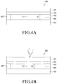
- FIGS. 4A and 4B are views illustrating a display according to an embodiment.
- a display 460 (e.g., the display device 160 or the display 360 ) may be mounted in a housing (e.g., the housing 303 ) of an electronic device (e.g., the electronic device 101 or 301 ) or may at least partially be disposed in the housing.
- the display 460 may include a transparent cover 461 (e.g., the cover 361 ), a touch sensor 463 , a spacer 465 , and/or a display panel 467 .
- the cover 461 may be disposed on the front surface of the electronic device or housing (e.g., the housing 303 ) or may be disposed to form at least a portion of the front surface.
- the touch sensor 463 may be disposed on the rear surface of the cover 461 .
- the touch sensor 463 may include a plurality of conductive lines to detect touch/hovering inputs.
- the conductive lines of the touch sensor 463 may have a linear grid pattern or diamond pattern.
- the touch sensor 463 may be operated according to first pattern signals of a first capacitive sensing scheme (e.g., a self capacitive sensing scheme or a first detection scheme) and second pattern signals of a second capacitive sensing scheme (e.g., a mutual capacitive sensing scheme or a second detection scheme).
- first capacitive sensing scheme e.g., a self capacitive sensing scheme or a first detection scheme
- second pattern signals of a second capacitive sensing scheme e.g., a mutual capacitive sensing scheme or a second detection scheme.
- the spacer 465 may space the touch sensor 463 apart from the display panel 467 .
- An air gap 469 of a thickness G 1 may be present between the touch sensor 463 and the display panel 467 .
- the spacer 465 may be stacked in a rectangular strap shape on rear edges (or periphery) or front edges (or periphery) of the display panel 467 .
- the spacer 465 may be formed of a single body or multiple parts spaced apart from each other.
- the spacer 465 may be formed of high-density polyurethane foam (e.g., PoronTM).
- the spacer 465 may be formed of one, or a combination, of an attaching member, e.g., an adhesive, a typical sealant, and a strength member shaped as a sphere, a cylinder, or a polyhedron.
- the attaching member may include a typical curable material, e.g., an ultraviolet (UV)-curable material.
- the strength member which may be a supporting member, may be formed of a metal, such as gold (Au), silver (Ag), or copper (Cu), or a conductive polymer, such as polyacetylene.
- the display panel 467 may include a plurality of pixels and may display various types of content (e.g., text, images, videos, icons, or symbols) through the pixels.
- content e.g., text, images, videos, icons, or symbols
- the display panel 467 may include a plurality of pixels arrayed in a matrix structure of M rows and N columns. Each pixel may include a red (R) sub-pixel, a green (G) sub-pixel, and a blue (B) sub-pixel.
- the display panel 467 may be configured to allow each pixel to emit light according to a selected combination of the RGB sub-pixels.
- the display panel 467 may include, e.g., a liquid crystal display (LCD), a light emitting diode (LED) display, an organic light emitting diode (OLED) display, or a microelectromechanical systems (MEMS) display, or an electronic paper display.
- LCD liquid crystal display
- LED light emitting diode
- OLED organic light emitting diode
- MEMS microelectromechanical systems
- a control circuit (e.g., the processor 120 , the touch sensor IC 253 , or a combination thereof) may provide driving signals to the touch sensor 463 and detect touch/hovering inputs based on signals sensed by the touch sensor 463 .
- a first capacitance C 1 may be produced between the touch sensor 463 and the display panel 467 by driving signals provided to the touch sensor 463 .
- an amount of force may be applied to the cover 461 , varying the thickness of the air gap 469 from the first thickness G 1 to a second thickness G 2 different from the first thickness G 1 .
- the capacitance between the touch sensor 463 and the display panel 467 may also be varied from the first capacitance C 1 to a second capacitance C 2 , and the variation in capacitance may cause noise.
- the noise may be reduced or removed according to a variation in the driving signal provided to the touch sensor 463 (e.g., a variation in a mean/peak/maximum voltage level/magnitude/width, or a duty cycle, rise/fall time or frequency of voltage pulses).
- a variation in the driving signal provided to the touch sensor 463 e.g., a variation in a mean/peak/maximum voltage level/magnitude/width, or a duty cycle, rise/fall time or frequency of voltage pulses.
- FIG. 5 is a block diagram illustrating an electronic device according to an embodiment.
- An electronic device 501 may include a housing (e.g., the housing 303 ), a proximity sensor 512 (e.g., the proximity sensor 12 e ), a pressure sensor 514 , a processor 520 (e.g., the processor 120 ), and/or touch circuitry 550 (e.g., the touch circuitry 250 ).
- the touch circuitry 550 may include a touch sensor 551 (e.g., the touch sensor 251 ) and a control circuit 553 (e.g., the touch sensor IC 253 ).
- the electronic device 501 may include a display device (e.g., the display device 160 or a touchscreen) having the touch circuitry 550 as its component.
- a display device e.g., the display device 160 or a touchscreen
- the touch circuitry 550 as its component.
- the electronic device 301 may omit one of the components or add another component (e.g., the communication module 190 or the memory 130 ).
- the proximity sensor 512 may be configured to detect an object's approach without any physical contact.
- the processor 520 or the control circuit 553 may obtain information related to the approach detected by the proximity sensor 512 .
- the proximity sensor 512 may output a preset (or approach-related) signal/data to the processor 520 or the control circuit 553 .
- the processor 520 or the control circuit 553 may read signals/data stored in the proximity sensor 512 .
- the proximity sensor 512 may include at least one of a capacitive proximity sensor to sense approach according to variations in capacitance, an inductive proximity sensor to produce a magnetic field through a coil and sense approach according to variations in electric current flowing through the coil, an ultrasonic proximity sensor to radiate an ultrasound wave and detect a reflected ultrasound wave, or a photo proximity sensor to emit an infrared (IR) beam and detect a reflected IR beam.
- a capacitive proximity sensor to sense approach according to variations in capacitance
- an inductive proximity sensor to produce a magnetic field through a coil and sense approach according to variations in electric current flowing through the coil
- an ultrasonic proximity sensor to radiate an ultrasound wave and detect a reflected ultrasound wave
- a photo proximity sensor to emit an infrared (IR) beam and detect a reflected IR beam.
- IR infrared
- the pressure sensor 514 may be configured to detect a pressure applied to a display (e.g., the display device 160 or the display 360 ) or the cover 361 .
- the processor 520 or the control circuit 553 may obtain information related to a pressure detected by the pressure sensor 514 .
- the pressure sensor 514 may output a preset (or pressure-related) signal/data to the processor 520 or the control circuit 553 .
- the processor 520 or the control circuit 553 may read signals/data stored in the pressure sensor 514 .
- the processor 520 may be configured to detect a first event related to mode switching and output a first control signal related to the mode switching to the control circuit 553 based on the detection of the first event.
- the mode switching-related first event may include at least one of detecting a preset state of the electronic device 501 , detecting a palm touch using the touch sensor 551 , detecting an approaching object using the proximity sensor 512 , detecting a touch pressure greater than or equal to a threshold using the pressure sensor 514 , executing a preset application (e.g., a communication/phone application), executing a preset function (e.g., communication/phone function), executing a function/application using a receiver, calling/receiving (or outputting a ring tone/vibration) or call connecting.
- a preset application e.g., a communication/phone application
- a preset function e.g., communication/phone function
- a function/application e.g., communication/phone function
- the processor 520 may transmit at least part of approach-related information received from the proximity sensor 512 to the control circuit 553 .
- the processor 520 may transmit at least part of pressure-related information received from the pressure sensor 514 to the control circuit 553 .
- the touch sensor 551 may be operated according to driving signals received from the control circuit 553 .
- the touch sensor 551 may transmit sensing signals detected from the conductive lines to the control circuit 553 .
- the sensing signals from the touch sensor 551 may represent capacitances, voltages, or currents.
- the control circuit 553 may receive sensing signals from the touch sensor 551 and produce touch information based on the sensing signals.
- the control circuit 553 may transmit the touch information to the processor 520 .
- the processor 520 may perform operations/functions based on the touch information received from the control circuit 553 .
- the touch information may include at least one of touch positions, touch coordinates, touch pressures, touch areas, touch types, or touch angles.
- the control circuit 553 may output a first driving signal to the touch sensor 551 in a first operation mode.
- the control circuit 553 may detect a first event related to mode switching and output a second driving signal different from the first driving signal to the touch sensor 551 based on the detection of the first event.
- the mode switching-related first event may include at least one of detecting a preset state of the electronic device 501 , receiving a first control signal (e.g., an instruction to switch to a second operation mode) related to the mode switching, detecting a palm touch using the touch sensor 551 , detecting an approaching object using the proximity sensor 512 , detecting a touch pressure greater than or equal to a threshold using the pressure sensor 514 , executing a preset application (e.g., a communication/phone application), executing a preset function (e.g., communication/phone function), executing a function/application using a receiver, calling/receiving (or outputting a ring tone/vibration) or call connecting.
- a preset application e.g., a communication/phone application
- a preset function e.g., communication/phone function
- the second driving signal may have a different mean/peak/maximum voltage level/magnitude/width, duty cycle, voltage pulse rise/fall time, or frequency than a mean/peak/maximum voltage level/magnitude/width, duty cycle, voltage pulse rise/fall time, or frequency of the first driving signal.
- the first driving signal may include first pattern signals according to a first capacitive sensing scheme and second pattern signals according to a second capacitive sensing scheme, and the second driving signal may only include the second pattern signals according to the second capacitive sensing scheme.
- an electronic device may comprise a housing including a first plate and a second plate positioned opposite the first plate, a display positioned between the first plate and the second plate, a touch sensing panel positioned between the display and the first plate, spaced apart from the display by an air gap, and including a plurality of first conductive lines extending in a first direction and a plurality of second conductive lines extending in a different direction from the first direction as viewed from the first plate and crossing the plurality of first conductive lines, a wireless communication circuit, at least one processor functionally connected with the display, the panel, and the wireless communication circuit, and a memory functionally connected with the processor, wherein the memory may store instructions executed to enable the processor to detect an external object above or near the first plate; in a first operation, alternately use a first detection scheme and a second detection scheme, the first detection scheme detecting, independently, variations in capacitances of the plurality of first conductive lines and the plurality of second conductive lines during a first time period, and the second detection scheme
- the instructions may be executed to enable the processor to determine a state of the electronic device and switch between the first operation and the second operation based on at least part of the state.
- the electronic device may further comprise a speaker exposed through the first plate; and a proximity sensor position near the speaker, wherein the instructions may be executed to enable the processor to determine the state of the electronic device using the proximity sensor.
- the instructions may be executed to enable the processor to determine the state of the electronic device using the proximity sensor upon receiving a call through the wireless communication circuit.
- the first detection scheme and the modified first detection scheme may differ from each other in a frequency and/or voltages of signals provided to the plurality of first conductive lines and/or the plurality of second conductive lines.
- touch circuitry 550 may include a touch sensor 551 and a control circuit 553 electrically connected with the touch sensor 551 .
- the control circuit 553 may be configured to provide a first driving signal to the touch sensor 551 in a first operation mode, detect a first event related to mode switching, and provide a second driving signal different from the first driving signal to the touch sensor 551 in a second operation mode based on detecting the first event.
- an electronic device 501 may comprise a housing (e.g., the housing 303 ) and touch circuitry 550 mounted inside the housing or at least partially disposed inside the housing and configured to detect a touch or hovering.
- the touch circuitry 550 may be configured to operate in a first operation mode and according to a first driving signal, detect a first event related to mode switching, and operate in a second operation mode and according to a second driving signal different from the first driving signal based on detecting the first event.
- the second driving signal may have a different mean/peak/maximum voltage level/magnitude/width, duty cycle, or voltage pulse rise/fall time than a mean/peak/maximum voltage level/magnitude/width, duty cycle, or voltage pulse rise/fall time of the first driving signal.
- the second driving signal may have a different frequency from a frequency of the first driving signal.
- the first driving signal may include first pattern signals of a first capacitive sensing scheme (or a first detection scheme) and second pattern signals of a second capacitive sensing scheme (or a second detection scheme).
- the second driving signal may include second pattern signals of the second capacitive sensing scheme.
- the second driving signal may include third pattern signals of the first capacitive sensing scheme (or a modified first detection scheme) and the second pattern signals of the second capacitive sensing scheme.
- the first capacitive sensing scheme may be a self capacitive sensing scheme
- the second capacitive sensing scheme may be a mutual capacitive sensing scheme
- the third pattern signals may have a different mean/peak/maximum voltage level/magnitude/width, duty cycle, or voltage pulse rise/fall time than a mean/peak/maximum voltage level/magnitude/width, duty cycle, or voltage pulse rise/fall time of the first pattern signals.
- the third pattern signals may have a different frequency from a frequency of the third pattern signals.
- the total number of the third pattern signals may differ from the total number of the first pattern signals during one period.
- the mode switching-related event may include detecting a palm touch.
- the first event related to the mode switching includes at least one of detecting a preset state of the electronic device, receiving a first control signal related to the mode switching, detecting a palm touch, detecting an approaching object by a proximity sensor 512 , detecting a touch pressure greater than or equal to a threshold, executing a preset application, executing a preset function, call reception, or call connection.
- the touch circuitry 550 may be configured to detect a second event related to mode switching and switch an operation mode of the touch circuitry 550 from the second operation mode to the first operation mode based on detecting the second event.
- the second event related to the mode switching may include at least one of releasing the detection of a preset state of the electronic device, receiving a second control signal related to the mode switching, releasing a palm touch, releasing detection of an approach by the proximity sensor 512 , releasing a touch pressure greater than or equal to a threshold, terminating a preset application, terminating a preset function, releasing call reception, or releasing call connection.
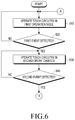
- FIG. 6 is a flowchart illustrating a method for changing modes of an electronic device according to an embodiment.
- the mode changing method may include operations 610 to 640 .
- Each step/operation of the mode changing method may be performed by at least one of an electronic device (e.g., the electronic device 101 , 301 , or 501 ), at least one processor (e.g., the processor 120 or 520 ) of the electronic device, touch circuitry (e.g., the touch circuitry 250 or 550 /control circuit (e.g., the touch sensor IC 253 or 553 )), or a controller/control circuit (e.g., the processor 120 or 520 ) and/or touch circuitry (e.g., the touch circuitry 250 or 550 /control circuit (e.g., the touch sensor IC 253 or 553 )) of the electronic device.
- at least one of operations 610 to 640 may be omitted or changed in order or may add other operations.
- the electronic device e.g., the processor or touch circuitry/control circuit
- the electronic device may operate in a first operation mode.
- the control circuit may periodically (or at regular intervals) provide first driving signals to a touch sensor (e.g., the touch sensor 251 or 551 ).
- the first driving signals may include first pattern signals of a first capacitive sensing scheme (e.g., a self capacitive sensing scheme or a first detection scheme) and second pattern signals of a second capacitive sensing scheme (e.g., a mutual capacitive sensing scheme or a second detection scheme).
- the control circuit may sequentially and individually provide the first pattern signals of the self capacitive sensing scheme to the conductive lines (e.g., X-axis (or TX) lines and Y-axis (or RX) lines) of the touch sensor.
- the control circuit may obtain first touch information based on first sensing signals detected at the conductive lines (e.g., X-axis (or TX) lines and Y-axis (or RX) lines).
- the control circuit may sequentially and individually provide the second pattern signals of the mutual capacitive sensing scheme to at least some (or at least a portion) (e.g., X-axis (or TX) lines) of the conductive lines of the touch sensor.
- the control circuit may obtain second touch information based on second sensing signals detected at conductive lines (e.g., Y-axis (or RX) lines).
- the control circuit may transmit the first and second touch information to the processor.
- the processor may perform operations/functions based on the first and second touch information received from the control circuit.
- the electronic device may identify whether a first event related to mode switching is detected/occurs.
- the electronic device may perform operation 630 upon detecting the first event, and if not, operation 610 .
- the first event may include at least one of detecting a preset state of the electronic device, receiving a first control signal (e.g., an instruction to switch to a second operation mode) related to the mode switching, detecting a palm touch, detecting an approaching object using the proximity sensor (e.g., the proximity sensor 12 e or 512 ), detecting a touch pressure greater than or equal to a threshold, executing a preset application (e.g., a communication/phone application), executing a preset function (e.g., communication/phone function), executing a function/application using a receiver, calling/receiving (or outputting a ring tone/vibration) or call connecting.
- a preset application e.g., a communication/phone application
- a preset function e.g., communication/phone function
- the electronic device e.g., the processor or touch circuitry/control circuit
- the electronic device may operate in a second operation mode.
- the control circuit may periodically (or at regular intervals) provide second driving signals to the touch sensor.
- the second driving signals may include third pattern signals of the first capacitive sensing scheme (or a modified first detection scheme) and/or second pattern signals of the second capacitive sensing scheme.
- the second driving signals may not include signals of the first capacitive sensing scheme but may include second pattern signals.
- the control circuit in the second operation mode, may sequentially provide the second pattern signals of the mutual capacitive sensing scheme to at least some (or at least a portion) (e.g., X-axis (or TX) lines) of the conductive lines of the touch sensor.
- the control circuit may obtain touch information based on second sensing signals detected at others (e.g., Y-axis (or RX) lines) of the conductive lines.
- the control circuit may transmit the touch information to the processor.
- the processor may perform operations/functions based on the information received from the control circuit.
- the electronic device may identify whether a second event related to mode switching is detected/occurs.
- the electronic device may perform operation 610 upon detecting the second event, and if not, operation 630 .
- the second event may include at least one of releasing the detection of the preset state of the electronic device, receiving a mode switching-related second control signal (e.g., an instruction to switch into the first operation mode), releasing the palm touch, releasing detection of the approach by the proximity sensor, releasing the touch pressure greater than or equal to the threshold, terminating the execution of the preset application, terminating the execution of the preset function, releasing the call reception, or releasing the call connection.
- a mode switching-related second control signal e.g., an instruction to switch into the first operation mode
- releasing the palm touch releasing detection of the approach by the proximity sensor
- releasing the touch pressure greater than or equal to the threshold terminating the execution of the preset application, terminating the execution of the preset function, releasing the call reception, or releasing the call connection.
- the mode switching method of the electronic device may include providing a first driving signal to a touch sensor in a first operation mode, detecting a first event related to mode switching, and providing a second driving signal different from the first driving signal to the touch sensor in a second operation mode based on detecting the first event.
- the first driving signal may include first pattern signals of a first capacitive sensing scheme (or a first detection scheme) and second pattern signals of a second capacitive sensing scheme (or a second detection scheme).
- the first capacitive sensing scheme may be a self capacitive sensing scheme
- the second capacitive sensing scheme may be a mutual capacitive sensing scheme
- the second driving signal may include third pattern signals of the first capacitive sensing scheme (or a modified first detection scheme) and the second pattern signals of the second capacitive sensing scheme.
- the third pattern signals may have a different mean/peak/maximum voltage level/magnitude/width, duty cycle, voltage pulse rise/fall time, or frequency than a mean/peak/maximum voltage level/magnitude/width, duty cycle, voltage pulse rise/fall time, or frequency of the first pattern signals.
- FIGS. 7A and 7B are views illustrating driving signals according to an embodiment.
- first driving signals may include first pattern signals 711 according to a first capacitive sensing scheme (e.g., a self capacitive sensing scheme) and second pattern signals 713 according to a second capacitive sensing scheme (e.g., a mutual capacitive sensing scheme).
- the control circuit e.g., the touch sensor IC 253 or 553
- the control circuit may sequentially and individually provide the first pattern signals 711 to the conductive lines (e.g., X-axis (or TX) lines) and Y-axis (or RX) lines) of the touch sensor.
- the control circuit may sequentially and individually provide the second pattern signals 713 to at least some (or at least a portion) (e.g., X-axis (or TX) lines) of the conductive lines of the touch sensor.
- the second driving signal 720 may only include the second pattern signals of the second capacitive sensing scheme.
- the control circuit may periodically (or at regular intervals) provide second driving signals to the touch sensor.
- the control circuit may sequentially and individually provide the second pattern signals 723 to at least some (or at least a portion) (e.g., X-axis (or TX) lines) of the conductive lines of the touch sensor.
- a noise reduction of about ⁇ 6 dB may be achieved in a frequency range from 100 Hz to 1 kHz.
- the frame/period of the first driving signal 710 shown in FIG. 7A may be the same or different from the frame/period of the second driving signal 720 shown in FIG. 7B .
- FIGS. 8A, 8B, and 8C are views illustrating driving signals according to an embodiment.
- a first driving signal may include first pattern signals 811 according to a first capacitive sensing scheme (e.g., a self capacitive sensing scheme) and second pattern signals (not shown) according to a second capacitive sensing scheme (e.g., a mutual capacitive sensing scheme).
- the first pattern signals 811 may have a first voltage level/magnitude V 1 , a first interval D 1 , and a first frequency (total number of signals per unit time).
- a second driving signal may include third pattern signals 821 of the first capacitive sensing scheme (e.g., a self capacitive sensing scheme) and second pattern signals (not shown) according to the second capacitive sensing scheme (e.g., a mutual capacitive sensing scheme).
- the third pattern signals 821 may have a second voltage/magnitude V 2 (e.g., 30% to 70%, or 40% to 60%, of the first voltage level/magnitude V 1 ) smaller than the first voltage level/magnitude V 1 , the first interval D 1 , and the first frequency (total number of signals per unit time).
- a second driving signal may include fourth pattern signals 831 of the first capacitive sensing scheme (e.g., a self capacitive sensing scheme) and second pattern signals (not shown) according to the second capacitive sensing scheme (e.g., a mutual capacitive sensing scheme).
- the fourth pattern signals 831 may have the first voltage level/magnitude V 1 , a second interval D 2 larger than the first interval D 1 , and a second frequency (e.g., 30% to 70%, or 40% to 60%, of the first frequency) smaller than the first frequency.
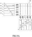
- FIGS. 9A to 9D are views illustrating a method for operating an electronic device according to an embodiment.
- a touch sensor 903 may include a plurality of conductive lines to detect touch/hovering inputs.
- the touch sensor 903 may include first to fifth X-axis lines X 0 , X 1 , X 2 , X 3 , and X 4 and first to fifth Y-axis lines Y 0 , Y 1 , Y 2 , Y 3 , and Y 4 .
- a control circuit may sequentially and individually provide first pattern signals 911 , 913 , 915 , 917 , and 919 of a first capacitive sensing scheme (e.g., a self capacitive sensing scheme) to the first to fifth X-axis lines X 0 , X 1 , X 2 , X 3 , and X 4 .
- a first capacitive sensing scheme e.g., a self capacitive sensing scheme
- sensing signals detected at the first to fifth X-axis lines X 0 , X 1 , X 2 , X 3 , and X 4 may have the same voltage level/magnitude/waveform.
- the control circuit may sequentially and individually provide first pattern signals 921 , 923 , 925 , 927 , and 929 of the first capacitive sensing scheme to the first to fifth Y-axis lines Y 0 , Y 1 , Y 2 , Y 3 , and Y 4 .
- sensing signals detected at the first to fifth Y-axis lines Y 0 , Y 1 , Y 2 , Y 3 , and Y 4 may have the same voltage level/magnitude/waveform.
- a sensing signal 915 a detected at the third X-axis line X 2 may have a different level/magnitude/waveform from sensing signals 911 a , 913 a , 917 a , and 919 a detected at the other X-axis lines X 0 , X 1 , X 3 , and X 4 .
- a sensing signal 925 a detected at the third Y-axis line Y 2 may have a different level/magnitude/waveform from sensing signals 921 a , 923 a , 927 a , and 929 a detected at the other Y-axis lines Y 0 , Y 1 , Y 3 , and Y 4 .
- the control circuit may determine the crossing of the third X-axis line X 2 and the third Y-axis line Y 2 as the position of the touch based on the variation in voltage level/magnitude/waveform of the sensing signal 915 a detected at the third X-axis line X 2 and the sensing signal 925 a detected at the third Y-axis line Y 2 .
- the control circuit may sequentially and individually provide second pattern signals 941 , 943 , 945 , 947 , and 949 of a second capacitive sensing scheme (e.g., a mutual capacitive sensing scheme) to the first to fifth X-axis lines X 0 , X 1 , X 2 , X 3 , and X 4 .
- a second capacitive sensing scheme e.g., a mutual capacitive sensing scheme
- sensing signals may simultaneously be detected at the first to fifth Y-axis lines Y 0 , Y 1 , Y 2 , Y 3 , and Y 4 corresponding to providing the signal to one of the X-axis lines.
- sensing signals detected at the first to fifth Y-axis lines Y 0 , Y 1 , Y 2 , Y 3 , and Y 4 may have the same voltage level/magnitude/waveform 951 .
- a sensing signal detected at the third Y-axis line Y 2 may have a different level/magnitude/waveform 953 from the voltage level/magnitude/waveform 951 of sensing signals detected at the other Y-axis lines Y 0 , Y 1 , Y 3 , and Y 4 .
- the control circuit may determine the crossing of the third X-axis line X 2 and the third Y-axis line Y 2 as the position of the touch based on the variation in voltage level/magnitude/waveform 953 of the sensing signal detected at the third Y-axis line Y 2 .
- FIG. 10 is a flowchart illustrating a method for changing modes of an electronic device according to an embodiment.
- the mode changing method may include operations 1010 to 1050 .
- Each step/operation of the mode changing method may be performed by at least one of an electronic device (e.g., the electronic device 101 , 301 , or 501 ), at least one processor (e.g., the processor 120 or 520 ) of the electronic device, touch circuitry (e.g., the touch circuitry 250 or 550 /control circuit (e.g., the touch sensor IC 253 or 553 )), or a controller/control circuit (e.g., the processor 120 or 520 ) and/or touch circuitry (e.g., the touch circuitry 250 or 550 /control circuit (e.g., the touch sensor IC 253 or 553 )) of the electronic device.
- at least one of operations 1010 to 1050 may be omitted or changed in order or may add other operations.
- Operations 610 , 620 , 630 , and 640 of the mode changing method shown in FIG. 6 may correspond to operations 1010 , 1030 , 1040 , and 1050 , respectively, of the mode changing method, and thus, no repetitive description is presented below.
- the electronic device e.g., the processor or touch circuitry/control circuit
- the electronic device may operate in a first operation mode.
- the control circuit may periodically (or at regular intervals) provide first driving signals to a touch sensor (e.g., the touch sensor 251 or 551 ).
- the first driving signals may include first pattern signals of a first capacitive sensing scheme (e.g., a self capacitive sensing scheme and second pattern signals of a second capacitive sensing scheme (e.g., a mutual capacitive sensing scheme).
- the electronic device e.g., the processor or the touch circuitry/control circuit
- the electronic device may determine whether a preset condition is met.
- the electronic device may perform operation 1030 when the condition is met and perform operation 1010 unless the condition is met.
- the condition may include at least one of detecting a circumstance preset on the electronic device, executing a preset application (e.g., a communication/phone application), selecting a graphical element (or item, such as a button, icon, menu, or menu item) requiring the operation of a speaker/receiver, receiving an instruction/signal requiring the operation of the speaker/receiver, executing a user input/instruction or a preset function (e.g., a communication/phone function), executing a function/application using the receiver, call dispatch/reception (or ring tone/vibration output) or call connection.
- a preset application e.g., a communication/phone application
- selecting a graphical element or item, such as a button, icon, menu, or menu item
- receiving an instruction/signal requiring the operation of the speaker/receiver executing a user input/instruction or a preset function (e.g., a communication/phone function)
- the preset context for the electronic device may include at least one of the electronic device being positioned or reaching a preset area/place, reaching a preset time, the electronic device operating according to a preset operation pattern (e.g., executing an application(s)), or the current status (e.g., the battery status, wireless signal reception status, or memory status) of the electronic device matching a preset status.
- a preset operation pattern e.g., executing an application(s)
- the current status e.g., the battery status, wireless signal reception status, or memory status
- the circumstance preset on the electronic device may be determined based on the use history information about the electronic device.
- the electronic device may identify whether a first event related to mode switching is detected/occurs.
- the electronic device may perform operation 1040 upon detecting the first event, and if not, operation 1010 .
- the first event may include at least one of detecting a preset state of the electronic device, receiving a first control signal (e.g., an instruction to switch to a second operation mode) related to the mode switching, detecting a palm touch, detecting an approaching object using the proximity sensor (e.g., the proximity sensor 12 e or 512 ), or detecting a touch pressure greater than or equal to a threshold.
- a first control signal e.g., an instruction to switch to a second operation mode
- the electronic device e.g., the processor or touch circuitry/control circuit
- the electronic device may operate in a second operation mode.
- the control circuit may periodically (or at regular intervals) provide second driving signals to the touch sensor.
- the second driving signals may include third pattern signals of the first capacitive sensing scheme and/or second pattern signals of the second capacitive sensing scheme.
- the second driving signals may not include signals of the first capacitive sensing scheme but may include second pattern signals.
- the control circuit in the second operation mode, may sequentially provide the second pattern signals of the mutual capacitive sensing scheme to at least some (or at least a portion) (e.g., X-axis (or TX) lines) of the conductive lines of the touch sensor.
- the control circuit may obtain touch information based on second sensing signals detected at others (e.g., Y-axis (or RX) lines) of the conductive lines.
- the control circuit may transmit the touch information to the processor.
- the processor may perform operations/functions based on the information received from the control circuit.
- the electronic device may identify whether a second event related to mode switching is detected/occurs.
- the electronic device may perform operation 1010 upon detecting the second event, and if not, operation 1040 .
- the second event may include at least one of releasing the detection of the preset state of the electronic device, receiving a mode switching-related second control signal (e.g., an instruction to switch into the first operation mode), releasing the palm touch, releasing detection of the approach by the proximity sensor, releasing the touch pressure greater than or equal to the threshold, releasing the preset condition, terminating the execution of the preset application, terminating the execution of the preset function, releasing the call reception, or releasing the call connection.
- a mode switching-related second control signal e.g., an instruction to switch into the first operation mode
- releasing the palm touch releasing detection of the approach by the proximity sensor
- releasing the touch pressure greater than or equal to the threshold releasing the preset condition
- terminating the execution of the preset application terminating the execution of the preset function
- FIG. 11 is a view illustrating a method for recognizing a palm touch on an electronic device according to an embodiment.
- a processor e.g., the processor 120 or 520 of an electronic device (e.g., the electronic device 101 , 301 , or 501 ) or touch circuitry (e.g., the touch circuitry 250 or 550 )/control circuit (e.g., the touch sensor IC 253 or 553 ) of the electronic device may detect an area 1110 where a touch is made on a display (e.g., the display device 160 or the display 360 ). For example, the processor or the touch circuitry/control circuit may determine whether the touched area 1110 corresponds to a palm touch based on at least one of the size of the touched area 1110 , the major axis 1113 , or the minor axis 1115 .
- the processor or the touch circuitry/control circuit may compare the size of the touched area 1110 with a preset threshold, and when the size of the touched area 1110 is greater than or equal to the threshold, the processor or the touch circuitry/control circuit may determine that a palm touch has occurred.
- a storage medium storing commands configured to be executed by at least one processor to enable the at least one processor to perform at least one operation that may include providing a first driving signal to a touch sensor in a first operation mode, detecting a first event related to mode switching, and providing a second driving signal different from the first driving signal to the touch sensor in a second operation mode based on detecting the first event.
- touch sensing signals may be controlled with the user's eye coming in contact or close to the electronic device, allowing the user to be less influenced by noise.
Landscapes
- Engineering & Computer Science (AREA)
- General Engineering & Computer Science (AREA)
- Theoretical Computer Science (AREA)
- Human Computer Interaction (AREA)
- Physics & Mathematics (AREA)
- General Physics & Mathematics (AREA)
- User Interface Of Digital Computer (AREA)
- Environmental & Geological Engineering (AREA)
- Computer Networks & Wireless Communication (AREA)
- Signal Processing (AREA)
Abstract
Description
Claims (15)
Applications Claiming Priority (2)
| Application Number | Priority Date | Filing Date | Title |
|---|---|---|---|
| KR10-2017-0105018 | 2017-08-18 | ||
| KR1020170105018A KR102405666B1 (en) | 2017-08-18 | 2017-08-18 | Electronic apparatus and method for controlling touch sensing signals and storage medium |
Publications (2)
| Publication Number | Publication Date |
|---|---|
| US20190056836A1 US20190056836A1 (en) | 2019-02-21 |
| US11216115B2 true US11216115B2 (en) | 2022-01-04 |
Family
ID=65360461
Family Applications (1)
| Application Number | Title | Priority Date | Filing Date |
|---|---|---|---|
| US16/104,138 Active 2038-09-07 US11216115B2 (en) | 2017-08-18 | 2018-08-17 | Electronic device and method for controlling touch sensing signals and storage medium |
Country Status (5)
| Country | Link |
|---|---|
| US (1) | US11216115B2 (en) |
| EP (1) | EP3642701B1 (en) |
| KR (1) | KR102405666B1 (en) |
| CN (1) | CN111052055B (en) |
| WO (1) | WO2019035607A1 (en) |
Cited By (1)
| Publication number | Priority date | Publication date | Assignee | Title |
|---|---|---|---|---|
| US12073043B2 (en) | 2021-11-29 | 2024-08-27 | Samsung Electronics Co., Ltd. | Electronic device and method for detecting touch input thereof |
Families Citing this family (4)
| Publication number | Priority date | Publication date | Assignee | Title |
|---|---|---|---|---|
| JP2022131470A (en) * | 2021-02-26 | 2022-09-07 | セイコーエプソン株式会社 | printer |
| US11532878B2 (en) * | 2021-04-23 | 2022-12-20 | Advanced Semiconductor Engineering, Inc. | Electronic device and wearable device |
| US11487384B1 (en) * | 2021-06-22 | 2022-11-01 | Novatek Microelectronics Corp. | Touch device and communication method thereof |
| WO2023096221A1 (en) * | 2021-11-29 | 2023-06-01 | 삼성전자 주식회사 | Electronic apparatus and method for detecting touch input of electronic apparatus |
Citations (21)
| Publication number | Priority date | Publication date | Assignee | Title |
|---|---|---|---|---|
| KR20040085770A (en) | 2003-04-01 | 2004-10-08 | 엘지.필립스 엘시디 주식회사 | Touch panel integrated liquid crystal panel |
| KR20100009020A (en) | 2008-07-17 | 2010-01-27 | 주식회사 케이티테크 | Apparatus using touch screen equipped with resistive overlay layer and capacitive overlay layer and method using the same |
| JP2010092152A (en) | 2008-10-06 | 2010-04-22 | Hitachi Displays Ltd | Input device and display device equipped with the same |
| KR20130078937A (en) | 2012-01-02 | 2013-07-10 | 엘지전자 주식회사 | Touch screen and controlling method thereof |
| US20130265276A1 (en) * | 2012-04-09 | 2013-10-10 | Amazon Technologies, Inc. | Multiple touch sensing modes |
| US20130285971A1 (en) * | 2012-04-30 | 2013-10-31 | John Greer Elias | Wide dynamic range capacitive sensing |
| US20150002466A1 (en) | 2009-05-26 | 2015-01-01 | Japan Display West Inc. | Touch sensor, display device, and electronic apparatus |
| US8970537B1 (en) * | 2013-09-30 | 2015-03-03 | Synaptics Incorporated | Matrix sensor for image touch sensing |
| US20150062062A1 (en) * | 2013-09-04 | 2015-03-05 | Lg Display Co., Ltd. | Touch Integrated Circuit And Display Device Integrated With Touch Screen Using The Same |
| US20150145802A1 (en) * | 2013-11-25 | 2015-05-28 | Apple Inc. | Reconfigurable circuit topology for both self-cap and mutual cap sensing |
| US20150177880A1 (en) | 2013-12-20 | 2015-06-25 | Lg Display Co., Ltd. | Display device integrated with touch screen panel and method of driving the same |
| US20150346889A1 (en) * | 2014-05-30 | 2015-12-03 | Marvell World Trade Ltd. | Touch panel and touch detection circuit |
| US20160035290A1 (en) * | 2014-08-01 | 2016-02-04 | Hideep Inc. | Smartphone |
| US20160048234A1 (en) * | 2014-08-18 | 2016-02-18 | Stmicroelectronics Asia Pacific Pte Ltd | System and method of communication between a capacitive touch screen and an active stylus |
| US20160370948A1 (en) * | 2015-06-22 | 2016-12-22 | Samsung Electronics Co., Ltd. | Touch screen controller, touch sensing device, and touch sensing method |
| US20170003816A1 (en) | 2009-07-10 | 2017-01-05 | Apple Inc. | Touch and hover sensing |
| US20170024124A1 (en) * | 2014-04-14 | 2017-01-26 | Sharp Kabushiki Kaisha | Input device, and method for controlling input device |
| US20170269751A1 (en) * | 2016-03-16 | 2017-09-21 | Hideep Inc. | Touch input device |
| US20180260051A1 (en) * | 2015-10-30 | 2018-09-13 | Hideep Inc. | Pressure detector for performing pressure detection accuracy correction, and touch input device |
| US20190102010A1 (en) * | 2017-09-29 | 2019-04-04 | Apple Inc. | Touch sensor panel architecture with multiple sensing mode capabilities |
| US10409414B2 (en) * | 2016-02-04 | 2019-09-10 | Samsung Electronics Co., Ltd. | Touch sensing apparatus, touch sensing method, touch sensing system, and display system using the same |
Family Cites Families (10)
| Publication number | Priority date | Publication date | Assignee | Title |
|---|---|---|---|---|
| CN102487542A (en) * | 2010-12-01 | 2012-06-06 | 宏碁股份有限公司 | Wireless network device with power supply management mechanism and power supply management method thereof |
| KR101914077B1 (en) * | 2012-01-02 | 2019-01-14 | 엘지이노텍 주식회사 | Light emitting device, light emitting device package, and light unit |
| CN106055183B (en) * | 2012-12-30 | 2019-11-08 | 比亚迪股份有限公司 | Capacitive detection circuit |
| US9477356B2 (en) * | 2013-06-19 | 2016-10-25 | Qualcomm Incorporated | System and method to drive touch panel to measure hover |
| US9274656B2 (en) * | 2013-06-27 | 2016-03-01 | Atmel Corporation | Fast scanning for mutual capacitance screens |
| KR102125327B1 (en) * | 2014-01-24 | 2020-06-22 | 삼성전자주식회사 | Operating Method For Touch Module and Electronic Device supporting the same |
| US9367169B2 (en) * | 2014-03-31 | 2016-06-14 | Stmicroelectronics Asia Pacific Pte Ltd | Method, circuit, and system for hover and gesture detection with a touch screen |
| KR20160014481A (en) * | 2014-07-29 | 2016-02-11 | 삼성전자주식회사 | Device Operated on Idle Mode and Method thereof |
| KR20160104976A (en) * | 2015-02-27 | 2016-09-06 | 삼성전자주식회사 | Touch module and electronic device and operating method thereof |
| KR102381659B1 (en) * | 2015-03-10 | 2022-04-04 | 삼성디스플레이 주식회사 | Flexible display device |
-
2017
- 2017-08-18 KR KR1020170105018A patent/KR102405666B1/en active IP Right Grant
-
2018
- 2018-08-10 WO PCT/KR2018/009195 patent/WO2019035607A1/en unknown
- 2018-08-10 CN CN201880050809.1A patent/CN111052055B/en active Active
- 2018-08-10 EP EP18845880.6A patent/EP3642701B1/en active Active
- 2018-08-17 US US16/104,138 patent/US11216115B2/en active Active
Patent Citations (24)
| Publication number | Priority date | Publication date | Assignee | Title |
|---|---|---|---|---|
| KR20040085770A (en) | 2003-04-01 | 2004-10-08 | 엘지.필립스 엘시디 주식회사 | Touch panel integrated liquid crystal panel |
| KR20100009020A (en) | 2008-07-17 | 2010-01-27 | 주식회사 케이티테크 | Apparatus using touch screen equipped with resistive overlay layer and capacitive overlay layer and method using the same |
| JP2010092152A (en) | 2008-10-06 | 2010-04-22 | Hitachi Displays Ltd | Input device and display device equipped with the same |
| US20150002466A1 (en) | 2009-05-26 | 2015-01-01 | Japan Display West Inc. | Touch sensor, display device, and electronic apparatus |
| US20170003816A1 (en) | 2009-07-10 | 2017-01-05 | Apple Inc. | Touch and hover sensing |
| KR20130078937A (en) | 2012-01-02 | 2013-07-10 | 엘지전자 주식회사 | Touch screen and controlling method thereof |
| US20130265276A1 (en) * | 2012-04-09 | 2013-10-10 | Amazon Technologies, Inc. | Multiple touch sensing modes |
| US20130285971A1 (en) * | 2012-04-30 | 2013-10-31 | John Greer Elias | Wide dynamic range capacitive sensing |
| US20150062062A1 (en) * | 2013-09-04 | 2015-03-05 | Lg Display Co., Ltd. | Touch Integrated Circuit And Display Device Integrated With Touch Screen Using The Same |
| KR20150027529A (en) | 2013-09-04 | 2015-03-12 | 엘지디스플레이 주식회사 | Touch ic and display device integrated with touch screen using the same |
| US8970537B1 (en) * | 2013-09-30 | 2015-03-03 | Synaptics Incorporated | Matrix sensor for image touch sensing |
| US20150145802A1 (en) * | 2013-11-25 | 2015-05-28 | Apple Inc. | Reconfigurable circuit topology for both self-cap and mutual cap sensing |
| US20150177880A1 (en) | 2013-12-20 | 2015-06-25 | Lg Display Co., Ltd. | Display device integrated with touch screen panel and method of driving the same |
| US20170024124A1 (en) * | 2014-04-14 | 2017-01-26 | Sharp Kabushiki Kaisha | Input device, and method for controlling input device |
| EP2958000A2 (en) | 2014-05-30 | 2015-12-23 | Marvell World Trade Ltd. | Touch panel and touch detection circuit |
| US20150346889A1 (en) * | 2014-05-30 | 2015-12-03 | Marvell World Trade Ltd. | Touch panel and touch detection circuit |
| US20160035290A1 (en) * | 2014-08-01 | 2016-02-04 | Hideep Inc. | Smartphone |
| US20160048234A1 (en) * | 2014-08-18 | 2016-02-18 | Stmicroelectronics Asia Pacific Pte Ltd | System and method of communication between a capacitive touch screen and an active stylus |
| US20160370948A1 (en) * | 2015-06-22 | 2016-12-22 | Samsung Electronics Co., Ltd. | Touch screen controller, touch sensing device, and touch sensing method |
| US10156935B2 (en) * | 2015-06-22 | 2018-12-18 | Samsung Electronics Co., Ltd. | Touch screen controller, touch sensing device, and touch sensing method |
| US20180260051A1 (en) * | 2015-10-30 | 2018-09-13 | Hideep Inc. | Pressure detector for performing pressure detection accuracy correction, and touch input device |
| US10409414B2 (en) * | 2016-02-04 | 2019-09-10 | Samsung Electronics Co., Ltd. | Touch sensing apparatus, touch sensing method, touch sensing system, and display system using the same |
| US20170269751A1 (en) * | 2016-03-16 | 2017-09-21 | Hideep Inc. | Touch input device |
| US20190102010A1 (en) * | 2017-09-29 | 2019-04-04 | Apple Inc. | Touch sensor panel architecture with multiple sensing mode capabilities |
Non-Patent Citations (3)
| Title |
|---|
| ISA/KR, "International Search Report and Written Opinion of the International Searching Authority," International Application No. PCT/KR2018/009195, dated Nov. 12, 2018, 10 pages. |
| Notification of the Reasons for Rejection dated Oct. 12, 2021, in connection with Korean Application No. 10-2017-0105018, 7 pages. |
| Supplementary European Search Report in connection with European Application No. 18845880.6 dated Jun. 8, 2020, 11 pages. |
Cited By (1)
| Publication number | Priority date | Publication date | Assignee | Title |
|---|---|---|---|---|
| US12073043B2 (en) | 2021-11-29 | 2024-08-27 | Samsung Electronics Co., Ltd. | Electronic device and method for detecting touch input thereof |
Also Published As
| Publication number | Publication date |
|---|---|
| CN111052055B (en) | 2024-02-09 |
| EP3642701A1 (en) | 2020-04-29 |
| CN111052055A (en) | 2020-04-21 |
| EP3642701B1 (en) | 2023-10-04 |
| EP3642701A4 (en) | 2020-07-08 |
| US20190056836A1 (en) | 2019-02-21 |
| KR102405666B1 (en) | 2022-06-07 |
| WO2019035607A1 (en) | 2019-02-21 |
| KR20190019723A (en) | 2019-02-27 |
Similar Documents
| Publication | Publication Date | Title |
|---|---|---|
| US11216115B2 (en) | Electronic device and method for controlling touch sensing signals and storage medium | |
| US20210012751A1 (en) | Electronic device and method for driving display of electronic device | |
| CN111034161B (en) | Electronic device including antenna using structure of display panel | |
| US10705655B2 (en) | Electronic device and method including elastic member for preventing/reducing performance degradation of pressure sensor | |
| KR20200007510A (en) | Flexible display and electronic device with the same | |
| KR102319372B1 (en) | Electronic device comprising biometric sensor | |
| US20190312090A1 (en) | Electronic device including bendable display | |
| US11169762B2 (en) | Electronic device including sub display and method of operating same | |
| US20210132728A1 (en) | Electronic device including sensor for detecting external input | |
| EP3958109A1 (en) | Method for reducing deterioration of display of electronic device, and foldable electronic device using method | |
| KR102578096B1 (en) | Electronic device for improving visual recognition of partial area of display | |
| US20200117308A1 (en) | Electronic device and method for determining touch input conditions based on type of touch input | |
| EP3660918B1 (en) | Electronic device including display panel including electrodes having different shapes for respective areas | |
| KR20190020481A (en) | Sensor and electronic device comprising at least one conductive layer for driving using a signal of the sensor | |
| EP4099417A1 (en) | Electronic device including display and method for controlling viewing angle of display | |
| US11379017B2 (en) | Electronic device and method for controlling pixels adjacent to sensor arranged inside display, and computer readable medium | |
| KR20220164431A (en) | Electronic device including a touchscreen and method of operating the same | |
| KR20200065324A (en) | Electronic device for preventing display burn-in | |
| EP4152129A1 (en) | Electronic device and synchronization method based on display driving signal in electronic device | |
| EP3992762B1 (en) | Electronic device and method for controlling digitizer panel of electronic device on basis of state of electronic pen | |
| KR102650376B1 (en) | Electronic device including sensor for touch input and sensor for hover input and method for operation thereof | |
| KR20240087476A (en) | Electronic device and method for recognizing accessory using the same | |
| KR20240041187A (en) | Electronic device and method for controlling touch input | |
| KR20220101445A (en) | Electronic device and method for controlling display operation in electronic device | |
| KR20230018282A (en) | Electronic device including a in-display optical sensor |
Legal Events
| Date | Code | Title | Description |
|---|---|---|---|
| FEPP | Fee payment procedure |
Free format text: ENTITY STATUS SET TO UNDISCOUNTED (ORIGINAL EVENT CODE: BIG.); ENTITY STATUS OF PATENT OWNER: LARGE ENTITY |
|
| AS | Assignment |
Owner name: SAMSUNG ELECTRONICS CO., LTD, KOREA, REPUBLIC OF Free format text: ASSIGNMENT OF ASSIGNORS INTEREST;ASSIGNORS:LEE, SANG-YUP;KANG, TAE-KYOUNG;KIM, YEON-HWAN;AND OTHERS;REEL/FRAME:047083/0344 Effective date: 20180620 |
|
| STPP | Information on status: patent application and granting procedure in general |
Free format text: DOCKETED NEW CASE - READY FOR EXAMINATION |
|
| STPP | Information on status: patent application and granting procedure in general |
Free format text: NON FINAL ACTION MAILED |
|
| STPP | Information on status: patent application and granting procedure in general |
Free format text: RESPONSE TO NON-FINAL OFFICE ACTION ENTERED AND FORWARDED TO EXAMINER |
|
| STPP | Information on status: patent application and granting procedure in general |
Free format text: FINAL REJECTION MAILED |
|
| STPP | Information on status: patent application and granting procedure in general |
Free format text: DOCKETED NEW CASE - READY FOR EXAMINATION |
|
| STPP | Information on status: patent application and granting procedure in general |
Free format text: AWAITING TC RESP., ISSUE FEE NOT PAID |
|
| STPP | Information on status: patent application and granting procedure in general |
Free format text: NOTICE OF ALLOWANCE MAILED -- APPLICATION RECEIVED IN OFFICE OF PUBLICATIONS |
|
| STPP | Information on status: patent application and granting procedure in general |
Free format text: AWAITING TC RESP., ISSUE FEE NOT PAID |
|
| STPP | Information on status: patent application and granting procedure in general |
Free format text: AWAITING TC RESP, ISSUE FEE PAYMENT RECEIVED |
|
| STPP | Information on status: patent application and granting procedure in general |
Free format text: PUBLICATIONS -- ISSUE FEE PAYMENT VERIFIED |
|
| STCF | Information on status: patent grant |
Free format text: PATENTED CASE |