US11215849B2 - Pantoscopic tilt measurement device - Google Patents
Pantoscopic tilt measurement device Download PDFInfo
- Publication number
- US11215849B2 US11215849B2 US16/902,363 US202016902363A US11215849B2 US 11215849 B2 US11215849 B2 US 11215849B2 US 202016902363 A US202016902363 A US 202016902363A US 11215849 B2 US11215849 B2 US 11215849B2
- Authority
- US
- United States
- Prior art keywords
- spectacle frame
- image
- recording apparatus
- image recording
- user
- Prior art date
- Legal status (The legal status is an assumption and is not a legal conclusion. Google has not performed a legal analysis and makes no representation as to the accuracy of the status listed.)
- Active
Links
Images


Classifications
-
- G—PHYSICS
- G06—COMPUTING; CALCULATING OR COUNTING
- G06Q—INFORMATION AND COMMUNICATION TECHNOLOGY [ICT] SPECIALLY ADAPTED FOR ADMINISTRATIVE, COMMERCIAL, FINANCIAL, MANAGERIAL OR SUPERVISORY PURPOSES; SYSTEMS OR METHODS SPECIALLY ADAPTED FOR ADMINISTRATIVE, COMMERCIAL, FINANCIAL, MANAGERIAL OR SUPERVISORY PURPOSES, NOT OTHERWISE PROVIDED FOR
- G06Q30/00—Commerce
- G06Q30/06—Buying, selling or leasing transactions
- G06Q30/0601—Electronic shopping [e-shopping]
-
- G—PHYSICS
- G02—OPTICS
- G02C—SPECTACLES; SUNGLASSES OR GOGGLES INSOFAR AS THEY HAVE THE SAME FEATURES AS SPECTACLES; CONTACT LENSES
- G02C13/00—Assembling; Repairing; Cleaning
- G02C13/003—Measuring during assembly or fitting of spectacles
-
- G—PHYSICS
- G06—COMPUTING; CALCULATING OR COUNTING
- G06T—IMAGE DATA PROCESSING OR GENERATION, IN GENERAL
- G06T11/00—2D [Two Dimensional] image generation
- G06T11/60—Editing figures and text; Combining figures or text
-
- G—PHYSICS
- G06—COMPUTING; CALCULATING OR COUNTING
- G06T—IMAGE DATA PROCESSING OR GENERATION, IN GENERAL
- G06T7/00—Image analysis
- G06T7/70—Determining position or orientation of objects or cameras
- G06T7/73—Determining position or orientation of objects or cameras using feature-based methods
-
- G—PHYSICS
- G06—COMPUTING; CALCULATING OR COUNTING
- G06T—IMAGE DATA PROCESSING OR GENERATION, IN GENERAL
- G06T2200/00—Indexing scheme for image data processing or generation, in general
- G06T2200/24—Indexing scheme for image data processing or generation, in general involving graphical user interfaces [GUIs]
-
- G—PHYSICS
- G06—COMPUTING; CALCULATING OR COUNTING
- G06T—IMAGE DATA PROCESSING OR GENERATION, IN GENERAL
- G06T2207/00—Indexing scheme for image analysis or image enhancement
- G06T2207/30—Subject of image; Context of image processing
- G06T2207/30196—Human being; Person
- G06T2207/30201—Face
Definitions
- Pantoscopic tilt is an important parameter for manufacture of corrective spectacles. It is generally defined as a tilt of the spectacle frame front in relation to the vertical line, as defined by gravity, and is measured in degrees. Pantoscopic tilt is caused by two factors: design of the spectacle frame and the head posture of the user.
- Corrective spectacles are made by glazing (or mounting) ophthalmic lenses into spectacle frames.
- Certain types of ophthalmic lenses which are made to order for the user commonly known as prescription ophthalmic lenses, explicitly require pantoscopic tilt as an input in their manufacture.
- Most other ophthalmic lenses assume an average pantoscopic tilt value.
- This average pantoscopic tilt value is at ophthalmic lens manufacturer's discretion and is usually between 8 and 12 degrees. Therefore, it is important for opticians who sell the corrective spectacles to check if the actual pantoscopic tilt for the spectacle frame chosen by the user is within this range. Otherwise the glazed ophthalmic lenses may not provide the optimal viewing experience to the user and may not provide the prescribed correction.
- pantoscopic tilt is measured accurately for each user and the chosen spectacle frame prior to manufacture of corrective spectacles, irrespective of the type of ophthalmic lens prescribed or chosen by the user.
- pantoscopic tilt is measured in various ways. Most commonly it is measured by manual tools based on the principle of plumb line, wherein the flat surface of the tool is placed on the surface of the spectacle frame or trial lens and an indicating part moves so as to indicate the angle of tilt.
- manual tools based on the principle of plumb line, wherein the flat surface of the tool is placed on the surface of the spectacle frame or trial lens and an indicating part moves so as to indicate the angle of tilt.
- US patent application publication no. US2013/0042489 A1 The main problem of manual tools is their inherent inaccuracy since the movable part of the device may not fully tilt due to friction. In addition, determining the exact angle value from the dial is often difficult.
- automated systems for measurement of many optical parameters, including pantoscopic tilt can be used. One such system is described by U.S. Pat. No. 7,740,355.
- a method for measurement of pantoscopic tilt includes:
- a spectacle frame composed of a frame front and two temples
- an image recording apparatus which includes sensors to determine orientation of said apparatus in space along all three axes, and which can display and record spatial orientation information
- step d capturing the aligned image described in step d and at the same time recording spatial sensor data
- the method comprises of the image recording apparatus being positioned in such a way that the profile of the spectacle frame front is fully visible and that in step c) the alignment feature is aligned with the spectacle frame front lengthwise. This can make the alignment more precise and therefore measurement of pantoscopic tilt more accurate. Further, while capturing the image in step e) the spectacle frame front profile should appear as thin as possible while being displayed to ensure correct positioning of the image recording apparatus, thus increasing measurement accuracy.
- the image capture in step e) can be done automatically when predetermined image parameters are satisfied, such as the frame front profile being fully visible.
- the method comprises attaching a feature, such as a marker strip with symbols of known dimensions and positioning, to the spectacle frame temple which is going to be visible in step d).
- a feature such as a marker strip with symbols of known dimensions and positioning
- This feature can aid in calculating the relative spatial positions of the image capturing apparatus and the spectacle frame and facilitate automated image capture.
- this spatial data can be used to improve accuracy of pantoscopic tilt measurement.
- a system comprises a computer with a user interface; and a non-transitory computer readable program for causing the computer to perform the following steps when executed: displaying the alignment feature c) on the display; instructing the user to position the image recording apparatus as described in d); instructing the user to record the image or optionally performing step e) automatically when given parameters are satisfied; and displaying the pantoscopic tilt from spatial sensor data.
- the determined pantoscopic tilt and/or spatial sensor data can be transmitted to another device specified by the user in the user interface.
- the system comprises an image recording apparatus, such as a smartphone or a tablet computer, which includes at least the elements of: a camera, display, spatial orientation sensors, user interface and computational hardware.
- an image recording apparatus such as a smartphone or a tablet computer, which includes at least the elements of: a camera, display, spatial orientation sensors, user interface and computational hardware.
- any of the aforementioned embodiments may be implemented in combination with or via a non-transitory computer-readable storage medium.
- the non-transitory computer-readable storage medium may execute a program or cause a computer or similar device configured to execute a program in accordance with any of the aforementioned embodiments and/or method steps described herein. Further, the non-transitory computer-readable storage medium may be stored locally or provided via an external source or device.
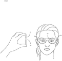
- FIG. 1 shows a frontal view of a user and an image recording apparatus.
- FIG. 2 a shows a side view of a user and an image recording apparatus with a display showing an image feed.
- FIG. 2 b shows a side view of a user and an image recording apparatus with a display showing an image feed wherein a marker strip is attached to a spectacle frame temple.
- FIG. 3 shows a close-up view of the image captured and displayed by an image recording apparatus.
- FIG. 4 shows a flow chart depicting a process of measuring pantoscopic tilt.
- FIG. 1 shows a front view of the user wearing a spectacle frame consisting of a frame front 13 and temples 10 on both sides of the frame front.
- FIG. 1 also shows a profile view of the image recording apparatus 22 during image alignment and capture.
- FIG. 2 a shows a side view of the user and image recording apparatus 22 during image alignment and capture.
- FIG. 2 b also shows of the user and image recording apparatus 22 during image alignment and capture with a marker strip 25 attached to the spectacle frame temple 10 .
- FIG. 3 shows a close-up view of the image captured and displayed by an image recording apparatus.
- FIG. 4 shows a flow chart depicting a process of measuring pantoscopic tilt. The process with be discussed in combination with the images of the process shown in FIGS. 1-3 .
- FIGS. 1-3 include a spectacle frame, which consists of two frame temples 10 joined at the hinges with the frame front 13 , frame front side profile 14 , an image recording apparatus 22 with a capturing lens 33 , display 28 , alignment feature 16 , and pantoscopic tilt read-out 19 on the display.
- a spectacle frame which consists of two frame temples 10 joined at the hinges with the frame front 13 , frame front side profile 14 , an image recording apparatus 22 with a capturing lens 33 , display 28 , alignment feature 16 , and pantoscopic tilt read-out 19 on the display.
- Image recording apparatus 22 is a handheld electronic device, for example, a smartphone, a tablet computer or other handheld device which is capable of capturing an image, has a display, computational hardware, and spatial orientation sensors such as gyroscopes and accelerometers.
- the image recording apparatus 22 can include a computer system, software, an application and/or other configuration to perform at least one or more steps of method 50 shown in FIG. 4 .
- Spectacle frame is an actual frame chosen by the user in a shop or via an internet website, usually including temporary trial lenses instead of corrective lenses.
- the user may enter information regarding the spectacle frame into the user interface of the image recording apparatus 22 to specify the spectacle frame used for method 50 , and/or an order number or other input associated with the user to link the pantoscopic tilt measurement to a particular user and the chosen spectacle frame.
- the user When preparing for image capture, the user should have a natural posture of the head and neck for viewing an object in the distance, as shown in FIG. 2 a . It is important for accurate pantoscopic tilt measurement that the user does not lower his or her head downwards or tilt it upwards, but rather maintains it in a comfortable position while looking in a distance preferably straight ahead. In addition, it is not desirable for the user to bend their back, but rather keep it straight in a natural position for walking.
- the image recording apparatus 22 is positioned so that it is parallel to either of the spectacle frame temples 10 , as shown in FIG. 1 .
- the capturing lens 33 should be positioned in such a manner that it captures the image showing part of the temple 10 and most of the spectacle frame front side profile 14 as it is positioned on the user's face.
- Display 28 shows an exemplary alignment feature 16 superimposed on the real-time image feed from the capturing lens 33 in FIG. 2 a .
- Alignment feature 16 can be a line or a curve clearly distinguishable from the image feed and positioned at an angle to the lines defining the display edge, irrespective of the recording apparatus orientation (portrait or landscape).
- the alignment feature 16 is not shown on display 28 . Instead, a recorded image of the frame front side profile 14 is analyzed computationally and the line defining the alignment feature 16 is mathematically constructed and used for calculating pantoscopic tilt. These computations can be made on the apparatus itself or any other external device.
- FIG. 2 a shows a preferred embodiment wherein the image recording apparatus 22 is positioned so that the frame front side profile 14 image aligns with the alignment feature 16 as shown on the display 28 .
- the display 28 should only be showing the surface of the spectacle frame front side profile 14 , not either of the front or back surfaces of the spectacle frame front 13 , which indicates appropriate placement of the image recording apparatus 22 and the capturing lens 33 .
- an image is captured by pressing the recording portion 30 of the display 28 .
- spatial orientation sensor data is recorded and shown on the display 28 as measured pantoscopic tilt shown on the read-out 19 .
- FIG. 2 b shows an embodiment of a system, showing a marker strip 25 attached to the temple 10 which is shown on the display 28 .
- the marker strip 25 facilitates the measurement of distance and position of the spectacle frame temple 10 in relation to the capturing lens 33 .
- the marker strip 25 can aid in automating image capture and recording spatial orientation sensor data, as well as improving pantoscopic tilt measurement.
- FIG. 3 shows verification of the pantoscopic tilt measurement.
- the user is shown the captured image including the read-out of pantoscopic tilt 19 shown on display 28 of the image recording apparatus 22 .
- the user can compare the position of the spectacle frame front side profile 14 and the alignment feature 16 . If they align, as shown in FIG. 3 , the user completes the measurement process by noting the pantoscopic angle read-out 19 on the display 28 and pressing the recording portion 30 to finish. Otherwise, the process has to be repeated.
- comparison of the relative positions of the frame front side profile 14 and the alignment feature 16 can be done computationally on the image recording apparatus or another external device by analyzing the captured image and spatial orientation sensors' data.
- recording portion 30 enables transfer of recorded data, the captured image, and user and spectacle frame information to a computer system selected by the user in a format selected by the user.
- the communication and data transfer between image recording apparatus 22 and other systems can be through a network connection, or through a wireless connection.
- FIG. 4 shows a method 50 consisting of steps and are discussed in relation to FIGS. 1-3 :
- Step 52 Placement of the spectacle frame on the user's face in a comfortable position.
- FIGS. 1 and 2 a show the user with the spectacle frame placed on her face in a comfortable position as spectacles are intended to be worn, generally at a distance of 8 to 15 mm between the eyes and the back surfaces of the trial lenses.
- Step 54 Capture of the image of the frame front aligned with the screen feature.
- Image recording apparatus is positioned as shown in FIG. 1 so that the captured images are displayed as shown in FIG. 2 a .
- Image and sensor data are recorded either manually by selecting recording portion 30 or automatically.
- Step 56 Image verification
- the user visually compares the alignment of the frame front side profile 14 in relation to the screen feature 16 .
- this comparison can be done computationally, without user input.
- Step 55 Reposition the image recording apparatus
- step 56 If it is the case that it is determined in step 56 that there is misalignment of the frame front side profile 14 and screen feature 16 , the user can reposition the image recording apparatus to repeat step 54 . The user may make this determination or may be prompted by the user interface to perform this step based on computations which can be performed in step 56 .
- Step 58 Determine pantoscopic tilt
- This step can be done by analyzing the data collected from one or more sensors, such as spatial orientation sensors, in the image recording apparatus 22 .
- sensors generally include, but are not specifically limited to, gyroscopes and accelerometers, which measure data regarding the spatial orientation of the image recording apparatus, and more specifically angles in relation to the gravity vector.
- the spatial orientation sensors' data changes and thus pantoscopic tilt measurement, which is shown as a real-time read out 19 in degrees on the display 28 .
- the pantoscopic tilt can be measured but not displayed on the display 28 .
Abstract
Description
Claims (5)
Priority Applications (1)
| Application Number | Priority Date | Filing Date | Title |
|---|---|---|---|
| US16/902,363 US11215849B2 (en) | 2019-06-17 | 2020-06-16 | Pantoscopic tilt measurement device |
Applications Claiming Priority (2)
| Application Number | Priority Date | Filing Date | Title |
|---|---|---|---|
| US201962862158P | 2019-06-17 | 2019-06-17 | |
| US16/902,363 US11215849B2 (en) | 2019-06-17 | 2020-06-16 | Pantoscopic tilt measurement device |
Publications (2)
| Publication Number | Publication Date |
|---|---|
| US20200393704A1 US20200393704A1 (en) | 2020-12-17 |
| US11215849B2 true US11215849B2 (en) | 2022-01-04 |
Family
ID=73745030
Family Applications (1)
| Application Number | Title | Priority Date | Filing Date |
|---|---|---|---|
| US16/902,363 Active US11215849B2 (en) | 2019-06-17 | 2020-06-16 | Pantoscopic tilt measurement device |
Country Status (1)
| Country | Link |
|---|---|
| US (1) | US11215849B2 (en) |
Families Citing this family (1)
| Publication number | Priority date | Publication date | Assignee | Title |
|---|---|---|---|---|
| US20220390771A1 (en) * | 2021-06-07 | 2022-12-08 | Blink Technologies Inc. | System and method for fitting eye wear |
Citations (16)
| Publication number | Priority date | Publication date | Assignee | Title |
|---|---|---|---|---|
| US4177571A (en) | 1978-05-22 | 1979-12-11 | Renier Gary L | Ophthalmic device for measuring vertex distance and pantoscopic tilt angle |
| AU2001100628A4 (en) | 2001-12-10 | 2002-01-31 | Sola International Holdings Ltd | Pantometer |
| US20050206834A1 (en) * | 2004-03-16 | 2005-09-22 | D Agostino Savino | Impact resistant lens, frame and tools and method for making same |
| FR2931001A1 (en) | 2008-05-06 | 2009-11-13 | Xavier Arthur Carriou | Spectacle glass-eye distance and pantoscopic angle measuring method, involves superimposing semi-transparent image of subject without frame and semi-transparent image of subject with frame for obtaining perfect concordance |
| US7740355B2 (en) | 2005-01-26 | 2010-06-22 | Rodenstock Gmbh | Device and method for determining optical parameters |
| US7950800B2 (en) * | 2007-04-18 | 2011-05-31 | Essilor International (Compagnie Generale D'optique) | Method of measuring at least one geometrico-physiognomic parameter for positioning a vision correcting eyeglass frame on the face of a wearer |
| US7996997B2 (en) | 2007-12-20 | 2011-08-16 | Hoya Corporation | Spectacle measuring tool |
| US8182089B2 (en) | 2008-05-15 | 2012-05-22 | Acep France | Apparatus for determining the orientation of ophthalmic lenses belonging to a frame |
| US20120167124A1 (en) * | 2010-12-23 | 2012-06-28 | Nagravision S.A. | System to identify a user of television services by using biometrics |
| US8333473B2 (en) | 2010-03-30 | 2012-12-18 | Seiko Epson Corporation | Wearing condition parameter measurement device for spectacle lens and wearing condition parameter measurement method for spectacle lens |
| US20130042489A1 (en) * | 2011-08-16 | 2013-02-21 | Oded Katzman | Device and method for measuring pantoscopic tilt |
| US20140218679A1 (en) * | 2011-05-23 | 2014-08-07 | Essilor International (Compagnie Generale D'optiqu | Method and device for determining at least one customized adjustment parameter of a lens carried by a spectacles frame facing the eye of a wearer |
| US9198576B1 (en) * | 2013-03-07 | 2015-12-01 | Hoya Corporation | Method and system for making ophthalmic measurements |
| US9395562B1 (en) * | 2015-04-07 | 2016-07-19 | Perfect Squares, Inc. | Method and apparatus for eye and eyewear characteristics measurement |
| US10386657B2 (en) * | 2017-05-06 | 2019-08-20 | Optikam Tech, Inc. | System and method for obtaining lens fabrication measurements that accurately account for natural head position |
| US20200262009A1 (en) * | 2019-02-19 | 2020-08-20 | William Joshua Becker | Welding location and order monitoring in welding systems |
-
2020
- 2020-06-16 US US16/902,363 patent/US11215849B2/en active Active
Patent Citations (16)
| Publication number | Priority date | Publication date | Assignee | Title |
|---|---|---|---|---|
| US4177571A (en) | 1978-05-22 | 1979-12-11 | Renier Gary L | Ophthalmic device for measuring vertex distance and pantoscopic tilt angle |
| AU2001100628A4 (en) | 2001-12-10 | 2002-01-31 | Sola International Holdings Ltd | Pantometer |
| US20050206834A1 (en) * | 2004-03-16 | 2005-09-22 | D Agostino Savino | Impact resistant lens, frame and tools and method for making same |
| US7740355B2 (en) | 2005-01-26 | 2010-06-22 | Rodenstock Gmbh | Device and method for determining optical parameters |
| US7950800B2 (en) * | 2007-04-18 | 2011-05-31 | Essilor International (Compagnie Generale D'optique) | Method of measuring at least one geometrico-physiognomic parameter for positioning a vision correcting eyeglass frame on the face of a wearer |
| US7996997B2 (en) | 2007-12-20 | 2011-08-16 | Hoya Corporation | Spectacle measuring tool |
| FR2931001A1 (en) | 2008-05-06 | 2009-11-13 | Xavier Arthur Carriou | Spectacle glass-eye distance and pantoscopic angle measuring method, involves superimposing semi-transparent image of subject without frame and semi-transparent image of subject with frame for obtaining perfect concordance |
| US8182089B2 (en) | 2008-05-15 | 2012-05-22 | Acep France | Apparatus for determining the orientation of ophthalmic lenses belonging to a frame |
| US8333473B2 (en) | 2010-03-30 | 2012-12-18 | Seiko Epson Corporation | Wearing condition parameter measurement device for spectacle lens and wearing condition parameter measurement method for spectacle lens |
| US20120167124A1 (en) * | 2010-12-23 | 2012-06-28 | Nagravision S.A. | System to identify a user of television services by using biometrics |
| US20140218679A1 (en) * | 2011-05-23 | 2014-08-07 | Essilor International (Compagnie Generale D'optiqu | Method and device for determining at least one customized adjustment parameter of a lens carried by a spectacles frame facing the eye of a wearer |
| US20130042489A1 (en) * | 2011-08-16 | 2013-02-21 | Oded Katzman | Device and method for measuring pantoscopic tilt |
| US9198576B1 (en) * | 2013-03-07 | 2015-12-01 | Hoya Corporation | Method and system for making ophthalmic measurements |
| US9395562B1 (en) * | 2015-04-07 | 2016-07-19 | Perfect Squares, Inc. | Method and apparatus for eye and eyewear characteristics measurement |
| US10386657B2 (en) * | 2017-05-06 | 2019-08-20 | Optikam Tech, Inc. | System and method for obtaining lens fabrication measurements that accurately account for natural head position |
| US20200262009A1 (en) * | 2019-02-19 | 2020-08-20 | William Joshua Becker | Welding location and order monitoring in welding systems |
Also Published As
| Publication number | Publication date |
|---|---|
| US20200393704A1 (en) | 2020-12-17 |
Similar Documents
| Publication | Publication Date | Title |
|---|---|---|
| US8459792B2 (en) | Method and systems for measuring interpupillary distance | |
| US8556420B2 (en) | Method and system for the on-line selection of a virtual eyeglass frame | |
| US7950800B2 (en) | Method of measuring at least one geometrico-physiognomic parameter for positioning a vision correcting eyeglass frame on the face of a wearer | |
| US10222634B2 (en) | Optical measurement aid device | |
| KR102190812B1 (en) | Method for determining at least one value of a parameter for customising a visual compensation device | |
| US8506078B2 (en) | Method for determining at least one geometric postural parameter when fitting a corrective spectacle frame on the face of a wearer in the anatomical posture thereof | |
| US8182089B2 (en) | Apparatus for determining the orientation of ophthalmic lenses belonging to a frame | |
| US9841615B2 (en) | Method for determining at least one optical design parameter for a progressive ophthalmic lens | |
| CN107250719B (en) | Spectacle wearing parameter measurement system, measurement program, measurement method thereof, and method for manufacturing spectacle lens | |
| EP3270099B2 (en) | Measurement device for eyeglasses-wearing parameter, measurement program for eyeglasses-wearing parameter, and position designation method | |
| US20170038608A1 (en) | Method for determining the far visual point for a spectacle lens and system therefor | |
| AU2015218530A1 (en) | Multiple-reference based system and method for ordering eyeglasses | |
| CN104718490A (en) | Methods and devices for evaluating eyewear fit | |
| US11215849B2 (en) | Pantoscopic tilt measurement device | |
| US20220397389A1 (en) | Spectacle lens shape measurement method | |
| AU2010249222A1 (en) | Configuration of lenses | |
| US11531217B2 (en) | Method for determining a parameter of an optical equipment | |
| US9529212B2 (en) | Method and device for determining at least one customized adjustment parameter of a lens carried by a spectacles frame facing the eye of a wearer | |
| US10591752B1 (en) | Method for adjusting prescription eyeglasses at a remote location based on measured data of a user's of the eyeglasses | |
| US11324399B2 (en) | Method and system for determining a pupillary distance of an individual | |
| US20220035182A1 (en) | Method for determining at least one geometrico-morphological parameters of a subject in a natural posture for determining a vision correction equipment | |
| CN113424098B (en) | Automatic establishment of parameters required for constructing eyeglasses |
Legal Events
| Date | Code | Title | Description |
|---|---|---|---|
| FEPP | Fee payment procedure |
Free format text: ENTITY STATUS SET TO UNDISCOUNTED (ORIGINAL EVENT CODE: BIG.); ENTITY STATUS OF PATENT OWNER: SMALL ENTITY |
|
| FEPP | Fee payment procedure |
Free format text: ENTITY STATUS SET TO SMALL (ORIGINAL EVENT CODE: SMAL); ENTITY STATUS OF PATENT OWNER: SMALL ENTITY |
|
| STPP | Information on status: patent application and granting procedure in general |
Free format text: DOCKETED NEW CASE - READY FOR EXAMINATION |
|
| STPP | Information on status: patent application and granting procedure in general |
Free format text: NON FINAL ACTION MAILED |
|
| STPP | Information on status: patent application and granting procedure in general |
Free format text: RESPONSE TO NON-FINAL OFFICE ACTION ENTERED AND FORWARDED TO EXAMINER |
|
| STPP | Information on status: patent application and granting procedure in general |
Free format text: FINAL REJECTION MAILED |
|
| STPP | Information on status: patent application and granting procedure in general |
Free format text: RESPONSE AFTER FINAL ACTION FORWARDED TO EXAMINER |
|
| STPP | Information on status: patent application and granting procedure in general |
Free format text: NOTICE OF ALLOWANCE MAILED -- APPLICATION RECEIVED IN OFFICE OF PUBLICATIONS |
|
| STPP | Information on status: patent application and granting procedure in general |
Free format text: PUBLICATIONS -- ISSUE FEE PAYMENT RECEIVED |
|
| STPP | Information on status: patent application and granting procedure in general |
Free format text: PUBLICATIONS -- ISSUE FEE PAYMENT VERIFIED |
|
| STCF | Information on status: patent grant |
Free format text: PATENTED CASE |
|
| AS | Assignment |
Owner name: OPTINNO B.V., NETHERLANDS Free format text: ASSIGNMENT OF ASSIGNORS INTEREST;ASSIGNOR:TEODOROVIC, MARKO;REEL/FRAME:059396/0940 Effective date: 20220324 |