US11215679B2 - Method and apparatus for detecting micro short circuit of battery - Google Patents
Method and apparatus for detecting micro short circuit of battery Download PDFInfo
- Publication number
- US11215679B2 US11215679B2 US16/365,352 US201916365352A US11215679B2 US 11215679 B2 US11215679 B2 US 11215679B2 US 201916365352 A US201916365352 A US 201916365352A US 11215679 B2 US11215679 B2 US 11215679B2
- Authority
- US
- United States
- Prior art keywords
- single battery
- detected
- battery
- charging
- value
- Prior art date
- Legal status (The legal status is an assumption and is not a legal conclusion. Google has not performed a legal analysis and makes no representation as to the accuracy of the status listed.)
- Active, expires
Links
Images


Classifications
-
- G—PHYSICS
- G01—MEASURING; TESTING
- G01R—MEASURING ELECTRIC VARIABLES; MEASURING MAGNETIC VARIABLES
- G01R31/00—Arrangements for testing electric properties; Arrangements for locating electric faults; Arrangements for electrical testing characterised by what is being tested not provided for elsewhere
- G01R31/50—Testing of electric apparatus, lines, cables or components for short-circuits, continuity, leakage current or incorrect line connections
- G01R31/52—Testing for short-circuits, leakage current or ground faults
-
- B—PERFORMING OPERATIONS; TRANSPORTING
- B60—VEHICLES IN GENERAL
- B60L—PROPULSION OF ELECTRICALLY-PROPELLED VEHICLES; SUPPLYING ELECTRIC POWER FOR AUXILIARY EQUIPMENT OF ELECTRICALLY-PROPELLED VEHICLES; ELECTRODYNAMIC BRAKE SYSTEMS FOR VEHICLES IN GENERAL; MAGNETIC SUSPENSION OR LEVITATION FOR VEHICLES; MONITORING OPERATING VARIABLES OF ELECTRICALLY-PROPELLED VEHICLES; ELECTRIC SAFETY DEVICES FOR ELECTRICALLY-PROPELLED VEHICLES
- B60L3/00—Electric devices on electrically-propelled vehicles for safety purposes; Monitoring operating variables, e.g. speed, deceleration or energy consumption
- B60L3/0023—Detecting, eliminating, remedying or compensating for drive train abnormalities, e.g. failures within the drive train
- B60L3/0046—Detecting, eliminating, remedying or compensating for drive train abnormalities, e.g. failures within the drive train relating to electric energy storage systems, e.g. batteries or capacitors
-
- G—PHYSICS
- G01—MEASURING; TESTING
- G01R—MEASURING ELECTRIC VARIABLES; MEASURING MAGNETIC VARIABLES
- G01R19/00—Arrangements for measuring currents or voltages or for indicating presence or sign thereof
- G01R19/165—Indicating that current or voltage is either above or below a predetermined value or within or outside a predetermined range of values
- G01R19/16533—Indicating that current or voltage is either above or below a predetermined value or within or outside a predetermined range of values characterised by the application
- G01R19/16538—Indicating that current or voltage is either above or below a predetermined value or within or outside a predetermined range of values characterised by the application in AC or DC supplies
- G01R19/16542—Indicating that current or voltage is either above or below a predetermined value or within or outside a predetermined range of values characterised by the application in AC or DC supplies for batteries
-
- G—PHYSICS
- G01—MEASURING; TESTING
- G01R—MEASURING ELECTRIC VARIABLES; MEASURING MAGNETIC VARIABLES
- G01R31/00—Arrangements for testing electric properties; Arrangements for locating electric faults; Arrangements for electrical testing characterised by what is being tested not provided for elsewhere
- G01R31/36—Arrangements for testing, measuring or monitoring the electrical condition of accumulators or electric batteries, e.g. capacity or state of charge [SoC]
- G01R31/382—Arrangements for monitoring battery or accumulator variables, e.g. SoC
- G01R31/3842—Arrangements for monitoring battery or accumulator variables, e.g. SoC combining voltage and current measurements
-
- G—PHYSICS
- G01—MEASURING; TESTING
- G01R—MEASURING ELECTRIC VARIABLES; MEASURING MAGNETIC VARIABLES
- G01R31/00—Arrangements for testing electric properties; Arrangements for locating electric faults; Arrangements for electrical testing characterised by what is being tested not provided for elsewhere
- G01R31/36—Arrangements for testing, measuring or monitoring the electrical condition of accumulators or electric batteries, e.g. capacity or state of charge [SoC]
- G01R31/385—Arrangements for measuring battery or accumulator variables
- G01R31/387—Determining ampere-hour charge capacity or SoC
-
- G—PHYSICS
- G01—MEASURING; TESTING
- G01R—MEASURING ELECTRIC VARIABLES; MEASURING MAGNETIC VARIABLES
- G01R31/00—Arrangements for testing electric properties; Arrangements for locating electric faults; Arrangements for electrical testing characterised by what is being tested not provided for elsewhere
- G01R31/36—Arrangements for testing, measuring or monitoring the electrical condition of accumulators or electric batteries, e.g. capacity or state of charge [SoC]
- G01R31/396—Acquisition or processing of data for testing or for monitoring individual cells or groups of cells within a battery
-
- H—ELECTRICITY
- H01—ELECTRIC ELEMENTS
- H01M—PROCESSES OR MEANS, e.g. BATTERIES, FOR THE DIRECT CONVERSION OF CHEMICAL ENERGY INTO ELECTRICAL ENERGY
- H01M10/00—Secondary cells; Manufacture thereof
- H01M10/42—Methods or arrangements for servicing or maintenance of secondary cells or secondary half-cells
- H01M10/425—Structural combination with electronic components, e.g. electronic circuits integrated to the outside of the casing
- H01M2010/4271—Battery management systems including electronic circuits, e.g. control of current or voltage to keep battery in healthy state, cell balancing
-
- Y—GENERAL TAGGING OF NEW TECHNOLOGICAL DEVELOPMENTS; GENERAL TAGGING OF CROSS-SECTIONAL TECHNOLOGIES SPANNING OVER SEVERAL SECTIONS OF THE IPC; TECHNICAL SUBJECTS COVERED BY FORMER USPC CROSS-REFERENCE ART COLLECTIONS [XRACs] AND DIGESTS
- Y02—TECHNOLOGIES OR APPLICATIONS FOR MITIGATION OR ADAPTATION AGAINST CLIMATE CHANGE
- Y02E—REDUCTION OF GREENHOUSE GAS [GHG] EMISSIONS, RELATED TO ENERGY GENERATION, TRANSMISSION OR DISTRIBUTION
- Y02E60/00—Enabling technologies; Technologies with a potential or indirect contribution to GHG emissions mitigation
- Y02E60/10—Energy storage using batteries
Definitions
- the present invention relates to the field of battery management, and in particular, to a method and an apparatus for detecting a micro short circuit of a battery for Electric Vehicle.
- a secondary battery is also referred to as a rechargeable battery or a storage battery.
- the secondary battery When being used, the secondary battery is affected by factors such as a battery raw material or a battery use manner, and may have safety problems such as a thermal runaway, over-charge, or over-discharge.
- the thermal runaway is an ultimate representation form of the battery safety problems, and one of main causes for the thermal runaway is a micro short circuit of a battery.
- the micro short circuit of the battery mainly includes a micro short circuit caused by an external factor, a micro short circuit caused by a change in an internal structure of the battery, and the like.
- the micro short circuit caused by the change in the internal structure of the battery undergoes a very long evolution process.
- a phenomenon of a micro short circuit of a battery at an early stage is not significant, and the micro short circuit of the battery is easily diagnosed as problems such as loose connection of a battery bolt, and is difficult to identify.
- a phenomenon of a micro short circuit occurring in a single battery included in a battery pack including a plurality of single batteries is contingent, which increases difficulty in identifying, from the battery pack, a single battery having a micro short circuit.
- the micro short circuit of the battery may cause severe safety problems such as a battery thermal runaway in a later period.
- the micro short circuit of the battery is one of battery security problems that urgently need to be resolved.
- a terminal voltage U i and an output current I of each single battery included in a secondary battery pack are collected, equivalent internal resistance Z i of each single battery is calculated, and whether a micro short circuit occurs in the single battery is determined by using a difference ⁇ Z i between Z i and reference resistance.
- the reference resistance is an average value of equivalent internal resistance of all single batteries in the battery pack. If a relatively large quantity of single batteries are connected in series in the battery pack, when the equivalent internal resistance of each single battery is calculated in real time by using a manner of detecting a micro short circuit in the prior art, a calculation amount is large, a hardware requirement on a battery management system (BMS) and implementation complexity are high.
- BMS battery management system
- Embodiments of the present invention provide a method and an apparatus for detecting a micro short circuit of a battery, which can improve accuracy in detecting a micro short circuit of a battery, enhance applicability of detecting a micro short circuit of a battery, and decrease a battery fault misjudgment rate.
- a method for detecting a micro short circuit of a battery may include:
- obtaining a first reference charge capacity at a first charging end moment and a second reference charge capacity at a second charging end moment of a to-be-detected single battery included in a to-be-detected battery pack where the reference charge capacity is a difference between an electric quantity of the to-be-detected single battery and an electric quantity of a reference single battery, and the reference single battery is a single battery, which has a largest voltage value at a charging end moment, in all single batteries included in the to-be-detected battery pack; and determining, based on a difference between the first reference charge capacity and the second reference charge capacity, that a micro short circuit occurs in the to-be-detected single battery.
- the difference between the first reference charge capacity and the second reference charge capacity includes a direct difference between the first reference charge capacity and the second reference charge capacity, and also includes a difference of another quantity calculated based on the first reference charge capacity and the second reference charge capacity.
- the micro short circuit includes a tiny short circuit that occurs inside a single battery or between positive and negative battery terminals.
- Calculation of the reference charge capacity of the single battery used in this embodiment of the present invention is related to a difference of electric quantities between the reference single battery and the to-be-detected single battery at a charging end moment, and a difference between charging electric quantities of single batteries is considered, so that detection on a short circuit status of a battery is more accurate and a detection accuracy rate is higher.
- a difference between reference charge capacities is used to determine a short circuit status of a battery.
- Even a tiny sign of a short circuit inside a battery can be detected based on an electric quantity difference between single batteries, so that a micro short circuit status of a single battery can be monitored starting from a tiny short circuit, thereby improving accuracy in detecting a short circuit inside a battery and decreasing a battery fault misjudgment rate.
- Monitoring on a short circuit of a battery can be started from an early stage, thereby better preventing risks, such as a thermal runaway, caused by a micro short circuit of a single battery.
- the determining, based on a difference between the first reference charge capacity and the second reference charge capacity, that a micro short circuit occurs in the to-be-detected single battery includes:
- the leakage current value of the to-be-detected single battery may be further calculated.
- the micro short circuit status of the to-be-detected single battery is more visually and clearly determined by using the leakage current value, so that the determining is more accurate, and applicability is higher.
- the determining, based on a difference between the first reference charge capacity and the second reference charge capacity, that a micro short circuit occurs in the to-be-detected single battery includes:
- the micro short circuit resistance of the to-be-detected single battery may be further calculated.
- the micro short circuit status of the to-be-detected single battery is more visually and clearly determined by using the micro short circuit resistance, so that diversity of manners of detecting a micro short circuit of a battery is increased, and flexibility is high.
- Calculation of the micro short circuit resistance may also be used to quantitatively detect the micro short circuit resistance of the to-be-detected single battery, so that the determining is more accurate, a battery fault misjudgment rate is decreased, and applicability is higher.
- the obtaining a first reference charge capacity at a first charging end moment and a second reference charge capacity at a second charging end moment of a to-be-detected single battery included in a to-be-detected battery pack includes:
- a remaining charging time of the to-be-detected single battery is calculated, and the reference charge capacity of the to-be-detected single battery is calculated by using the remaining charging time, so that calculation of the reference charge capacity is more closely associated with a charging status of a battery, and accuracy in determining a micro short circuit of a battery is higher.
- the determining a first remaining charging time of the to-be-detected single battery at the first charging end moment and a second remaining charging time of the to-be-detected single battery at the second charging end moment includes:
- the reference single battery can be determined by using the voltage value of each single battery in the to-be-detected battery pack, a charging voltage curve of the reference single battery is recorded, and further, the remaining charging time of the to-be-detected single battery can be determined by using the voltage difference. Determining of the remaining charging time of the to-be-detected single battery is more closely associated with a charging electric quantity status of each single battery in the to-be-detected battery pack, thereby improving calculation validity of the reference charge capacity of the to-be-detected single battery, and improving accuracy in determining a micro short circuit of a battery.
- the calculating, based on a charging current of the to-be-detected single battery, the first reference charge capacity corresponding to the first remaining charging time and the second reference charge capacity corresponding to the second remaining charging time includes:
- the reference charge capacity of the to-be-detected single battery is calculated by using the integral, and a change amplitude of the reference charge capacity can be further controlled by using the preset battery capacity ratio, to adapt to error control of the reference charge capacity, thereby enhancing applicability of determining a micro short circuit status of a battery by using the reference charge capacity, and decreasing a misjudgment rate of a battery micro short circuit status.
- the calculating an average voltage value, over the time length, of each single battery in the to-be-detected battery pack includes:
- an average voltage value, over a time length between two charging end moments, of a voltage value of each single battery in the to-be-detected battery pack is calculated, and the micro short circuit resistance of the to-be-detected single battery is calculated by using the average voltage value, so that accuracy is higher, and applicability of detecting a micro short circuit of a battery is improved.
- the to-be-detected single battery is any one of at least one single battery in the to-be-detected battery pack;
- the method further includes:
- calculating a leakage current value of another single battery included in the to-be-detected battery pack and calculating a first average value of a leakage current value of all of the at least one single battery; and determining, based on the first average value, that a leakage current value of a target single battery of the at least one single battery needs to be corrected, where the leakage current value of the target single battery is less than a first preset current threshold.
- whether to correct the leakage current value of the target single battery in the to-be-detected battery pack is determined by calculating an average value of the leakage current values of the single batteries in the to-be-detected battery pack. This can prevent an abnormal single battery in the to-be-detected battery pack from affecting another single battery, and decrease a misjudgment rate of a micro short circuit of a battery, and applicability is higher.
- the method further includes:
- the first average value is less than a second preset current threshold, obtaining a leakage current value of at least one target single battery of the at least one single battery; and calculating a second average value of the leakage current value of the at least one target single battery, and adjusting a leakage current value of each target single battery based on the second average value to obtain a corrected leakage current value of each target single battery.
- a leakage current value of an abnormal to-be-detected single battery in the to-be-detected battery pack can be corrected, and the micro short circuit status of the to-be-detected single battery is determined by using a corrected leakage current value. This can improve accuracy in determining a micro short circuit status of a single battery, and enhance applicability of detecting a micro short circuit status of a single battery.
- the time length between the second charging end moment and the first charging end moment includes at least one consecutive or non-consecutive battery charging period, where
- the battery charging period is duration between two adjacent charging end moments of the to-be-detected battery pack.
- the second charging end moment and the first charging end moment are selected with high flexibility. This can improve flexibility in calculating the reference charge capacity of the to-be-detected single battery, and enhance applicability of detecting a micro short circuit status of a single battery.
- a value of the preset battery capacity ratio is greater than 0.9 and less than 1.1.
- an estimate of a leakage current value or micro short circuit resistance of the single battery can be controlled, by using the value of the preset battery capacity ratio, within a preset error range, and an estimation accuracy rate of the micro short circuit resistance of the single battery can be set within an acceptable range, thereby improving applicability of the method for detecting a micro short circuit of a battery provided in this embodiment of the present invention.
- an apparatus for detecting a micro short circuit of a battery may include:
- an obtaining module configured to obtain a first reference charge capacity at a first charging end moment and a second reference charge capacity at a second charging end moment of a to-be-detected single battery included in a to-be-detected battery pack, where the reference charge capacity is a difference between an electric quantity of the to-be-detected single battery and an electric quantity of a reference single battery, and the reference single battery is a single battery, which has a largest voltage value at a charging end moment, in all single batteries included in the to-be-detected battery pack;
- a determining module configured to determine, based on a difference that is obtained by the obtaining module and that is between the first reference charge capacity and the second reference charge capacity, that a micro short circuit occurs in the to-be-detected single battery.
- the determining module is configured to:
- use the obtaining module to: calculate the difference between the second reference charge capacity and the first reference charge capacity, and calculate a time length between the second charging end moment and the first charging end moment;
- the leakage current value is greater than or equal to a preset current threshold, determine that a micro short circuit occurs in the to-be-detected single battery.
- the determining module is configured to:
- use the obtaining module to: calculate the difference between the second reference charge capacity and the first reference charge capacity, and calculate a time length between the second charging end moment and the first charging end moment;
- the obtaining module uses the obtaining module to: calculate an average voltage value, over the time length, of each single battery in the to-be-detected battery pack, and determine micro short circuit resistance of the to-be-detected single battery based on the leakage current value;
- micro short circuit resistance is less than a preset resistance threshold, determine that a micro short circuit occurs in the to-be-detected single battery.
- the determining module is further configured to:
- the obtaining module is configured to:
- the first remaining charging time is required charging duration corresponding to a voltage difference between the to-be-detected single battery and the reference single battery at the first charging end moment;
- the second remaining charging time is required charging duration corresponding to a voltage difference between the to-be-detected single battery and the reference single battery at the second charging end moment.
- the determining module is configured to:
- the obtaining module is configured to:
- the detection apparatus further includes:
- a collection module configured to collect a voltage value of each single battery in the to-be-detected battery pack at each of N voltage sampling moments between the second charging end moment and the first charging end moment, where duration between two adjacent voltage sampling moments of the N voltage sampling moments is less than or equal to a preset voltage sampling period, and N is an integer greater than or equal to 2;
- the obtaining module is specifically configured to:
- the to-be-detected single battery is any one of at least one single battery in the to-be-detected battery pack;
- the obtaining module is further configured to:
- the determining module is further configured to:
- the leakage current value of the target single battery is less than a first preset current threshold.
- the detection apparatus further includes:
- a correction module configured to: when the first average value calculated by the obtaining module is less than a second preset current threshold, obtain a leakage current value of at least one target single battery of the at least one single battery; and use the obtaining module to: calculate a second average value of the leakage current value of the at least one target single battery, and adjust a leakage current value of each target single battery based on the second average value to obtain a corrected leakage current value of each target single battery.
- the time length between the second charging end moment and the first charging end moment includes at least one consecutive or non-consecutive battery charging period, where
- the battery charging period is duration between two adjacent charging end moments of the to-be-detected battery pack.
- an embodiment of the present invention provides a terminal device, including a memory and a processor.
- the memory is configured to store a group of program code.
- the processor is configured to invoke the program code stored in the memory, to perform the following operations:
- the reference charge capacity is a difference between an electric quantity of the to-be-detected single battery and an electric quantity of a reference single battery
- the reference single battery is a single battery, which has a largest voltage value at a charging end moment, in all single batteries included in the to-be-detected battery pack
- the processor is configured to:
- the leakage current value is greater than or equal to a preset current threshold, determine that a micro short circuit occurs in the to-be-detected single battery.
- the processor is configured to:
- micro short circuit resistance is less than a preset resistance threshold, determine that a micro short circuit occurs in the to-be-detected single battery.
- the processor is configured to:
- the first remaining charging time is required charging duration corresponding to a voltage difference between the to-be-detected single battery and the reference single battery at the first charging end moment;
- the second remaining charging time is required charging duration corresponding to a voltage difference between the to-be-detected single battery and the reference single battery at the second charging end moment.
- the processor is configured to:
- the processor is configured to:
- the processor is configured to:
- N is an integer greater than or equal to 2;
- the to-be-detected single battery is any one of at least one single battery in the to-be-detected battery pack.
- the processor is further configured to:
- the leakage current value of the target single battery is less than a first preset current threshold.
- the processor is further configured to:
- the time length between the second charging end moment and the first charging end moment includes at least one consecutive or non-consecutive battery charging period, where
- the battery charging period is duration between two adjacent charging end moments of the to-be-detected battery pack.
- Calculation of the reference charge capacity of the single battery used in the embodiments of the present invention is related to a difference of electric quantities between the reference single battery and the to-be-detected single battery at a charging end moment, and a difference between charging electric quantities of single batteries is considered, so that detection on a short circuit status of a battery is more thorough and a detection accuracy rate is higher.
- a difference between reference charge capacities is used to determine a short circuit status of a battery. Even a tiny sign of a short circuit inside a battery can be detected based on an electric quantity difference between single batteries, so that a micro short circuit status of a single battery can be monitored starting from a tiny short circuit.
- the micro short circuit resistance of each single battery can be estimated based on the leakage current value of the single battery, a tiny short circuit of a single battery can be detected in advance, and a quantitative result can be provided. This can improve accuracy in detecting a micro short circuit, and decrease a battery fault misjudgment rate, to achieve an objective of prevention, and ensure operation safety of a battery pack.
- FIG. 1 is a schematic structural diagram of a terminal device according to an embodiment of the present invention.
- FIG. 2 is a schematic flowchart of a method for detecting a micro short circuit of a battery according to an embodiment of the present invention
- FIG. 3 is another schematic flowchart of a method for detecting a micro short circuit of a battery according to an embodiment of the present invention
- FIG. 4 is a schematic structural diagram of an apparatus for detecting a micro short circuit of a battery according to an embodiment of the present invention.
- FIG. 5 is another schematic structural diagram of an apparatus for detecting a micro short circuit of a battery according to an embodiment of the present invention.
- a method for detecting a micro short circuit of a battery may be applied to a terminal device.
- the terminal device may be built in an existing BMS, or may be a device that includes an existing BMS. This may be determined according to a requirement of an actual application scenario, and is not limited herein.
- the terminal device may also be referred to as user equipment (UE), a mobile station (MS), a mobile terminal, or the like.
- the terminal device may alternatively be a portable mobile apparatus, a pocket-sized mobile apparatus, a handheld mobile apparatus, a computer built-in mobile apparatus, an in-vehicle mobile apparatus, or the like.
- the terminal device may be a mobile phone (also referred to as a “cellular” phone), a computer with mobility, an electric automobile, or the like.
- the method for detecting a micro short circuit of a battery provided in the embodiments of the present invention may be applied to another apparatus that uses a secondary battery. No limitation is imposed herein.
- FIG. 1 is a schematic structural diagram of a terminal device according to an embodiment of the present invention.
- the terminal device may include: a memory 100 , a processor 200 , a display 300 , and the like.
- the memory 100 stores a group of program code.
- the program code is used to implement operations such as recognition of a charging status, estimation of an electric quantity of a battery, calculation of a reference charge capacity, recording of a charging time, and calculation of micro short circuit resistance of a battery.
- the processor 200 is configured to read the program code in the memory 100 , and then perform a method defined by the program code. For example, the processor 200 may read the program code stored in the memory 100 to perform operations such as detecting a micro short circuit of a single battery in a battery pack.
- the processor 200 may include one or more processors, for example, the processor 200 may include one or more central processing units. When the processor 200 includes a plurality of processors, the plurality of processors may be integrated into a same chip, or may be independent chips, respectively.
- a processor may include one or more processing cores.
- the following embodiments use a multi-core processor as an example. However, the method for detecting a micro short circuit of a battery provided in the embodiments of the present invention may also be applied to a single-core processor.
- the processor may be specifically determined according to a requirement of an actual application scenario. No limitation is imposed herein.
- the memory 100 may further store other data different from the program code.
- the other data may include data generated after the processor executes the program code, for example, a voltage value during charging of a single battery.
- the memory 100 generally includes an internal memory and an external storage.
- the internal memory may be a random access memory (RAM), a read-only memory (ROM), a cache, or the like.
- the external storage may be a hard disk, an optical disc, a universal serial bus (USB) flash drive, a floppy disk, a tape drive, or the like.
- the program code is generally stored in the external storage. Before performing processing, the processor may load the program code from the external storage to the internal memory.
- the method for detecting a micro short circuit of a battery provided in the embodiments of the present invention may be applied to a battery pack including a plurality of single batteries, to detect a single battery that is in the battery pack and in which a micro short circuit occurs.
- a to-be-detected single battery provided in the embodiments of the present invention may be any battery in the battery pack.
- a reference charge capacity (C RC for short) of the to-be-detected single battery provided in the embodiments of the present invention is a difference between an electric quantity of the to-be-detected single battery and an electric quantity of a reference single battery in the battery pack when changing of the battery pack ends (namely, a charging end moment), where the reference single battery is a single battery that has a largest voltage value when changing of the battery pack ends.
- the charging end moment may be a moment at which the battery pack is fully charged, or may be a moment at which a user forcibly cuts off power to stop charging the battery pack.
- the moment at which the battery pack is fully charged may be specifically a moment at which any single battery in the battery pack is fully charged.
- the reference single battery may be a single battery that is earliest fully charged in the battery pack, or may be a single battery that has a largest voltage value (or a largest electric quantity) when charging of the battery pack is forcibly stopped. For example, when charging of the battery pack ends, a charging status of a single battery 1 in the battery pack reaches 100%. In this case, the battery 1 has a largest voltage value V1.
- the to-be-detected single battery is a single battery 2, and a charging status of the single battery 2 is 95%.
- a voltage value of the single battery 2 is V2, and V2 is less than V1. Therefore, it can be learned that C RC of the single battery 2 is (V1 ⁇ V2), and corresponds to a 5% charging electric quantity.
- FIG. 2 is a schematic flowchart of a method for detecting a micro short circuit of a battery according to an embodiment of the present invention.
- the method provided in this embodiment of the present invention includes the following operations.
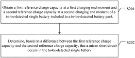
- Operation S 201 Obtain a first reference charge capacity at a first charging end moment and a second reference charge capacity at a second charging end moment of a to-be-detected single battery included in a to-be-detected battery pack.
- a terminal device may collect, by using an existing BMS, charging data obtained when a battery system is operating normally, and further may search, based on the charging data collected by the BMS, for a single battery that is in the battery pack and in which a micro short circuit occurs.
- the charging data may include: a charging end moment of the battery pack, a charging electric quantity of each single battery in the battery pack, a voltage value of each single battery in the battery pack, and the like.
- the charging data is merely an example rather than an exhaustive list, and includes but is not limited to the foregoing data. The data may be specifically determined according to an actual requirement. No limitation is imposed herein.
- the BMS may perform real-time detection and determining on a voltage value of each single battery in the battery pack, and may further record a charging voltage curve of each single battery in the charging process.
- the BMS may cut off a charging power supply to stop charging the battery pack. This moment is a full charging moment (namely, the charging end moment) of the battery pack.
- the BMS may record the full charging moment of the battery pack as the charging end moment of the battery pack.
- the BMS performs real-time detection on the voltage value of each single battery in the process of charging the battery pack, and if a power-off signal is detected when the preset fully charged voltage value is not yet detected, a power-off moment may be recorded as the charging end moment of the battery pack.
- the terminal may select, from the single batteries based on a voltage value, recorded by the BMS, of each single battery at the charging end moment, a single battery that has a largest voltage value as a reference single battery of another single battery, and further may obtain a charging voltage curve (set as a charging voltage curve 1) of the single battery that has the largest voltage value.
- the terminal may interpolate voltage values of other single batteries at the charging end moment to the charging voltage curve 1, to obtain charging moments, on the charging voltage curve 1, corresponding to the voltage values of the other single batteries, and further may calculate a remaining charging time of each of other single batteries.
- the BMS may record a complete charging voltage curve of each single battery in a whole charging process, or may record a part of the charging voltage curve in a specific time phase in the charging process, which has high flexibility.
- that the BMS records a complete charging voltage curve of a single battery in a whole charging process is simple to operate, requires support of relatively much memory, and has a relatively high requirement on hardware of the terminal. That the BMS records a part of the charging voltage curve of a single battery may save memory, and implement low costs and high applicability.
- a part of a charging voltage curve may be specifically a later-period charging voltage curve of a whole charging process of a single battery.
- the later period may be specifically a time segment that has a preset time length from the charging end moment.
- the specific preset time length may be set based on factors such as a hardware configuration condition of the BMS and micro short circuit resistance of a battery in an actual application scenario. No limitation is imposed herein.
- a part of a charging voltage curve may be, for example, a charging voltage curve of 10 minutes before the charging end moment (that is, a charging voltage curve corresponding to a time length of 10 minutes), or a charging voltage curve of 30 minutes before the charging end moment.
- a remaining charging time of the to-be-detected single battery may be required charging duration corresponding to a voltage difference between the to-be-detected single battery and the reference single battery at the charging end moment.
- the to-be-detected single battery is continuously charged, according to a charging law before the charging end moment, to the fully charged voltage value or the voltage value of the reference single battery, and then the power is cut off; a time length between the power-off moment and the charging end moment is the remaining charging time of the to-be-detected single battery.
- the terminal may determine, based on the voltage value of each single battery recorded in the BMS, a single battery (which is set as a first reference single battery and assumed to be a single battery 1 in the battery pack) that has a largest voltage value at a current charging end moment (the moment is set as a first charging end moment, and t0 is used as an example), and the voltage value (the voltage value is set as a first voltage value, and Vc1 is used as an example) of the to-be-detected single battery.
- a charging voltage curve (assumed to be a charging voltage curve 2) of the first reference single battery may be further obtained, and a charging moment (the moment is set as a first moment, and t1 is used as an example) corresponding to Vc1 is searched for on the charging voltage curve 2.
- the terminal may determine, based on the voltage value of each single battery recorded in the BMS, a single battery (which is set as a second reference single battery and assumed to be a single battery 1 in the battery pack.
- the second reference single battery may be another single battery, for example, a battery 3.
- the first reference single battery and the second reference single battery may be a same single battery or may be different single batteries, which may be specifically determined based on a charging status of a battery in an actual application scenario.
- the foregoing i th charging and (i+1) th charging may be two adjacent times of charging, or may be any two times of charging among a plurality of times of charging.
- a time interval between the adjacent two times of charging is a battery charging period
- a time interval between the i th charging and the (i+1) th charging may be one battery charging period, or may be a plurality of consecutive battery charging periods or a plurality of non-consecutive battery charging periods.
- the time interval between the i th charging and the (i+1) th charging may be 24 hours, or may be two consecutive battery charging periods (namely, 48 hours), or three consecutive battery charging periods (namely, 72 hours), or two non-consecutive battery charging periods (for example, 48 hours out of 72 hours, and the battery pack may be in an idle state, such as shutdown, during 24 hours therein), or the like.
- the time interval between the i th charging and the (i+1) th charging may be specifically determined according to a requirement of an actual application scenario. No limitation is imposed herein.
- the terminal may preset a quantity of times of recording charging data, which is assumed to be N times, where N is an integer greater than 1.
- the BMS may record an actual quantity of charging times, which is assumed to be M, where M is less than or equal to N. Each time the battery pack is charged, the BMS increases a value of M by 1. When the actual quantity M of charging times is greater than N, the BMS records only charging data for latest M times, and erases data recorded before the latest M times, to save memory of the BMS.
- the terminal may calculate a reference charge capacity C RC 1 (namely, a first reference charge capacity) of the single battery 2 in the i th charging and a reference charge capacity C RC 2 (namely, a second reference charge capacity) of the single battery 2 in the (i+1) th charging.
- the terminal when calculating C RC 1, may calculate an integral of a charging current (namely, a charging current of the to-be-detected single battery), during charging, of the battery pack in ⁇ t 0 to obtain an integral value (which is set as a first integral value) of the charging current in ⁇ t 0 .
- a charging current namely, a charging current of the to-be-detected single battery
- k is a preset battery capacity ratio.
- k may be set to 1 during calculation of C RC of each single battery in the battery pack.
- a calculation expression of C RC of each single battery is:
- k in consideration of differentiation between single batteries in a battery pack, k may be allowed to be set within a preset error range. Specifically, a value range of k may be set to [0.9,1.1], that is, k may be set to a value greater than or equal to 0.9 and less than or equal to 1.1.
- the terminal may scale up/down the integral value based on the preset battery capacity ratio to obtain C RC 1.
- k is a scaling ratio of the integral value of the charging current I in ⁇ t 0 . It is assumed that a capacity difference greater than 20% between single batteries is considered as a severe fault of the battery pack.
- an error when k is set to 1, and a theoretical error of the reference charge capacity estimated based on C RC 1 is within 20%, an error, when k is set to a range of 0.9 to 1.1, for estimating micro short circuit resistance may be set within the preset error range, and an estimation accuracy rate may be set within an acceptable range, thereby improving applicability of the method for detecting a micro short circuit of a battery provided in this embodiment of the present invention.
- the terminal may calculate an integral of the charging current (namely, the charging current of the to-be-detected single battery), during charging, of the battery pack in ⁇ t 1 to obtain an integral value (which is set as a second integral value) of the charging current in ⁇ t 1 .
- an integral of the charging current namely, the charging current of the to-be-detected single battery
- C RC 2 is a reference charge capacity of a current I in ⁇ t 1
- k is the preset battery capacity ratio.
- C RC 2 may be considered as a reference charge capacity obtained by scaling up/down the integral of the charging current I in ⁇ t 1 based on k.
- Operation S 202 Determine, based on a difference between the first reference charge capacity and the second reference charge capacity, that a micro short circuit occurs in the to-be-detected single battery.
- the terminal may analyze, based on C RC 1 and C RC 2, a micro short circuit status of a battery. Specifically, the terminal may determine, based on a difference between C RC 1 and C RC 2, whether a micro short circuit occurs in the battery.
- the difference between C RC 1 and C RC 2 includes a direct difference between C RC 1 and C RC 2, for example, (C RC 2 ⁇ C RC 1).
- the difference between C RC 1 and C RC 2 also includes a difference of another quantity calculated based on C RC , for example, a difference between two resistance values, obtained based on C RC 1 and C RC 2, of a resistor of a single battery.
- a specific representation form used for the difference between C RC 1 and C RC 2 may be determined according to a requirement of an actual application scenario. No limitation is imposed herein.
- the direct difference between C RC 2 and C RC 1 (for example, (C RC 2 ⁇ C RC 1)) is used as an example for description, and details are not described again in the following.
- the micro short circuit described in this embodiment of the present invention may include a tiny short circuit that occurs inside a single battery or between positive and negative battery terminals.
- a definition of short circuit severity of a tiny short circuit is related to a battery capacity, a battery shape, or the like of a battery, and is also related to a detection requirement of an actual application scenario.
- the definition of the short circuit severity may be specifically determined according to a requirement of an actual application scenario. No limitation is imposed herein.
- Calculation of C RC of the single battery used in this embodiment of the present invention is related to a difference of electric quantities between the reference single battery and the to-be-detected single battery at a charging end moment, and a difference between charging electric quantities of single batteries is considered, so that detection on a short circuit status of a battery is more thorough and a detection accuracy rate is higher. Further, in this embodiment of the present invention, a difference of C RC is used, to determine a short circuit status of a battery.
- Even a tiny sign of a short circuit inside a battery may be detected based on an electric quantity difference between single batteries, so that a micro short circuit status inside a single battery can be monitored starting from a tiny short circuit, thereby improving accuracy in detecting a short circuit inside a battery, decreasing a battery fault misjudgment rate, and preventing risks, such as a thermal runaway, caused by a short circuit inside a single battery as early as possible.
- the terminal may calculate a leakage current value of the to-be-detected single battery based on C RC 1 and C RC 2.
- the micro short circuit status of the to-be-detected single battery is more visually and clearly determined by using the leakage current value.
- the terminal may calculate the difference between C RC 2 and C RC 1, and calculate a time interval between the second charging end moment and the first charging end moment, namely, a time length between the second charging end moment and the first charging end moment.
- a ratio of the difference between C RC 2 and C RC 1 to the time length between the second charging end moment and the first charging end moment may be determined as the leakage current value of the to-be-detected single battery in the foregoing time interval.
- the terminal may calculate the leakage current value of each single battery in the time interval between two detections of C RC by using the following expression:
- I d C RC , i + 1 - C RC , i T i + 1 - T i
- I d is the leakage current value of the to-be-detected single battery
- C RC,i is C RC (for example, the foregoing C RC 1) of the to-be-detected single battery in the i th charging
- C RC,i+1 is C RC (for example, the foregoing C RC 2) of the to-be-detected single battery in the (i+1) th charging
- T i is the charging end moment of the to-be-detected single battery in the i th charging
- T i+1 (for example, the foregoing second charging end moment) is the charging end moment of the to-be-detected single battery in the (i+1) th charging.
- T i+1 ⁇ T i is a time interval between two calculations of C RC , for example, the time interval may be one or more of the foregoing battery charging periods.
- the time interval may be specifically determined according to a requirement of an actual application scenario. No limitation is imposed herein.
- the terminal may set, based on battery feature parameters such as stability of battery performance of a single battery in a battery pack or voltage detection precision, a preset current threshold of the leakage current value that is used to determine whether a micro short circuit occurs in the to-be-detected single battery. After obtaining the leakage current value of the to-be-detected single battery, the terminal may compare the leakage current value of the to-be-detected single battery with the preset current threshold. If the leakage current value of the to-be-detected single battery is greater than or equal to the preset current threshold, it may be determined that a micro short circuit occurs in the to-be-detected single battery.
- battery feature parameters such as stability of battery performance of a single battery in a battery pack or voltage detection precision
- the preset current threshold may be set based on a self-discharge current value of a battery that is in a normal working state.
- the self-discharge current value of the battery is related to features of the battery, and the preset current threshold may be greater than the self-discharge current value of the battery.
- the preset current threshold is related to battery feature parameters, such as stability of battery performance or voltage detection precision.
- the preset current threshold may be set to a relatively large value, to prevent misjudgment, caused by factors such as a low voltage detection precision, of a micro short circuit of a battery.
- the setting of the preset current threshold may be further related to a balance between a misjudgment rate of a detection algorithm used by a developer for detecting a micro short circuit of a battery and a mainly identified requirement on a micro short circuit degree.
- the preset current threshold may be properly increased; if the micro short circuit status of the to-be-detected single battery needs to be identified starting from a very tiny short circuit of the to-be-detected single battery, this threshold may be properly decreased.
- the preset current threshold may be specifically determined based on an actual application scenario. No limitation is imposed herein.
- the terminal may further correct the leakage current value of each single battery. For example, during charging, if a micro short circuit occurs in a reference single battery (namely, a single battery that is earliest fully charged, or a single battery that has a highest voltage value when power is cut off) in the battery pack, an obtained leakage current value of another single battery may be a negative value. In this case, a leakage current value of a single battery that may generate a negative leakage current needs to be corrected.
- FIG. 3 is another schematic flowchart of a method for detecting a micro short circuit of a battery according to an embodiment of the present invention. A method for correcting a leakage current value provided in this embodiment of the present invention includes the following Operations.
- Operation S 31 Calculate an average leakage current value of all single batteries in a battery pack.
- I dm is the average leakage current value of all the single batteries in the battery pack
- n is a quantity of single batteries included in the battery pack
- I d,i is a leakage current value of a single battery i.
- a terminal may calculate the average leakage current value (namely, a first average value) of all the single batteries included in the battery pack, and determine, based on the average leakage current value, whether to correct a leakage current value of each single battery that generates a negative leakage current.
- a first preset current threshold may be set to a value less than or equal to 0, and further, a single battery that has a leakage current value less than 0 may be set as a target single battery, to correct a leakage current value of the target single battery.
- a micro short circuit occurs in the reference single battery in the battery pack
- an electric leakage occurs in the reference single battery in a process of using the battery pack
- an electric quantity of the reference single battery is earliest depleted.
- an electric quantity of another single battery may not be depleted. Therefore, in a subsequent charging process, a difference of electric quantities between the another single battery and the reference single battery is becoming smaller.
- C RC,i is greater than C RC,i+1 Therefore, I d,i is less than 0, and in this case, a leakage current value needs to be corrected.
- the first preset current threshold and the second preset current threshold may be set to a same threshold (for example, 0), or may be set to different thresholds.
- the thresholds may be specifically determined according to a requirement of an actual application scenario. No limitation is imposed herein.
- Operation S 32 Determine whether I dm is negative; and if I dm is negative, perform step S 33 ; if I dm is not negative, perform operation S 35 .
- the terminal may set the second preset current threshold to 0.
- the first average value is less than 0, that is, I dm is negative, it may be determined that the leakage current value of the target single battery in the battery pack needs to be corrected.
- Operation S 33 Calculate an average leakage current value of all single batteries that have a negative leakage current value.
- I s is the average leakage current value (which is set as the second average value) of all the single batteries that have a negative leakage current value in the battery pack
- m is a quantity of the single batteries that have a negative leakage current value included in the battery pack
- m is less than n
- I d,i is a leakage current value of a single battery i.
- Operation S 34 Correct a leakage current value of each single battery that has a negative leakage current value to obtain a corrected leakage current value of the single battery.
- I ds,i I d,i ⁇ I s
- I ds,i is a corrected leakage current value of the single battery i.
- the terminal may subtract I s from the leakage current value of the target single battery, to obtain a corrected leakage current value.
- Operation S 35 Set a leakage current value that is less than or very close to 0 to 0.
- I ds,i 0 if( I ds,i ⁇ ), where ⁇ is a value that is close 0.
- the leakage current value of the single battery may be set to 0 when it is determined that a micro short circuit does not occur in the single battery, and that I ds,i is 0 is used to identify a single battery in which no short circuit occurs.
- the terminal may further calculate micro short circuit resistance of the to-be-detected single battery.
- a micro short circuit status of the to-be-detected single battery is more visually and clearly determined by using the micro short circuit resistance, and resistance and the like of a micro short circuit of the to-be-detected single battery can be quantitatively detected through calculation of the micro short circuit resistance.
- the terminal may calculate the micro short circuit resistance of the to-be-detected single battery based on the average voltage of the single battery in the battery pack.
- the leakage current value of the to-be-detected single battery includes the corrected leakage current value.
- the terminal may calculate the leakage current value based on the voltage value, recorded by the BMS, of each single battery in the battery pack at each voltage sampling moment in a time length between a second charging end moment and a first charging end moment.
- the BMS may collect the voltage value of each single battery in the battery pack based on a preset voltage sampling period.
- the preset voltage sampling period may be an existing voltage collection period of the BMS. No limitation is imposed herein.
- the terminal may obtain, from the voltage value of each single battery recorded by the BMS, the voltage value of the single batteries in the to-be-detected battery pack at each voltage sampling moment, and may further calculate an average value of voltage values of each single battery. If the to-be-detected battery pack is in an online state in the time length between the second charging end moment and the first charging end moment, N voltage sampling moments included in the time length between the second charging end moment and the first charging end moment may be determined based on the preset voltage sampling period.
- a first voltage sampling moment of the N voltage sampling moments is a voltage sampling moment that is closest to the first charging end moment, namely, the first collection moment in the time length when the BMS collects voltage values of the single batteries based on the existing voltage collection period.
- a last voltage sampling moment is a voltage sampling moment that is closest to the second charging end moment.
- a time length between two adjacent voltage sampling moments of the N voltage sampling moments is equal to the voltage sampling period of the BMS, namely, the foregoing preset voltage sampling period.
- the N voltage sampling moments are collection moments at which the BMS collects voltage values of the single batteries when the to-be-detected battery pack is in a normal working state. In a time segment in which the to-be-detected battery pack is in a working interrupted state, the BMS does not collect the voltage values of the single batteries.
- the BMS may continue to collect and record the voltage values of the single batteries in the battery pack.
- the N voltage sampling moments (assumed to be N1) between the second charging end moment and the first charging end moment are less than the N voltage sampling moments (assumed to be N2) between the second charging end moment and the first charging end moment in the foregoing application scenario in which the to-be-detected battery pack is in the online state in the time length between the second charging end moment and the second charging end moment.
- N1 is less than N2.
- the terminal may sequentially calculate a first average voltage value, which is set as U(kT), of each single battery in the to-be-detected battery pack at a K th voltage sampling moment in every two adjacent voltage sampling moments of the N voltage sampling moments, and a second average voltage value, which is set as U M ((k ⁇ 1)T), of each single battery in the to-be-detected battery pack at a (K ⁇ 1) th voltage sampling moment.
- a first average voltage value which is set as U(kT)
- U M ((k ⁇ 1)T) the terminal may calculate an average value of voltage values of each single battery in the to-be-detected battery pack at a first voltage sampling moment, and an average value of voltage values of each single battery in the to-be-detected battery pack at a second voltage sampling moment.
- the terminal scales up/down the first average voltage value and the second average voltage value based on a preset filtering coefficient, and adds up a scaled value of the first average voltage value and a scaled value of the voltage value of the to-be-detected battery pack to obtain an average voltage value (set as U M (kT)) at the K th voltage sampling moment.
- U M (kT) is an approximate average voltage value of the single batteries in the battery pack at this moment
- U M ((k ⁇ 1)T) is an approximate average voltage value of the single batteries in the battery pack at a previous moment
- U(kT) is an average voltage value of the voltage values of each single battery collected at this moment
- ⁇ is a filtering coefficient, and may be set to 0.0001 herein.
- the terminal may calculate the average voltage value (which may be specifically the approximate voltage value of the single batteries in the battery pack at the previous moment) of the voltage values of each single battery in the to-be-detected battery pack at the second voltage sampling moment, and an average voltage value (which may be specifically the average voltage value of the voltage values of each single battery collected at this moment) of the voltage values of each single battery in the to-be-detected battery pack at a third voltage sampling moment.
- the average voltage value (namely, the approximate average value of the voltage values of the single batteries in the battery pack at this moment) of the single batteries in the battery pack when K is equal to 3 may be calculated based on the expression of U M (kT).
- U M time length between the second charging end moment and the first charging end moment.
- the micro short circuit resistance of the single battery may be R ISC :
- R ISC micro short circuit resistance of a single battery i
- I ds is a leakage current of the single battery i
- Inf indicates that no short circuit occurs.
- a micro short circuit status of the single battery can be quantitatively determined through calculation of the micro short circuit resistance of the single battery, so that a detection accuracy rate is higher, and applicability is higher.
- the reference charge capacity of each single battery in the to-be-detected battery pack is estimated based on data collected by the BMS, and a micro short circuit current value (namely, a leakage current value) of each single battery is determined based on estimation of a change of the reference charge capacity of the single battery.
- a micro short circuit current value namely, a leakage current value
- No additional sensor is needed when the leakage current is detected by using data collected by the BMS, and an amount of data that needs to be stored and a data calculation amount are relatively small, so that difficulty in detecting a micro short circuit of a battery is decreased, and applicability is high.
- the micro short circuit resistance of each single battery can be estimated based on the leakage current value of the single battery, a micro short circuit status of each single battery in the battery pack can be detected before a severe micro short circuit occurs in the battery pack, a tiny short circuit can be detected in advance, and a quantitative result can be provided.
- This can improve accuracy in detecting a micro short circuit and decrease a battery fault misjudgment rate. Therefore, an objective of prevention is achieved, and operation safety of the battery pack is ensured.
- FIG. 4 is a schematic structural diagram of an apparatus for detecting a micro short circuit of a battery according to an embodiment of the present invention.
- the detection apparatus provided in this embodiment of the present invention includes:
- an obtaining module 41 configured to obtain a first reference charge capacity at a first charging end moment and a second reference charge capacity at a second charging end moment of a to-be-detected single battery included in a to-be-detected battery pack, where the reference charge capacity is a difference between an electric quantity of the to-be-detected single battery and an electric quantity of a reference single battery, and the reference single battery is a single battery, which has a largest voltage value at a charging end moment, in all single batteries included in the to-be-detected battery pack; and
- a determining module 42 configured to determine, based on a difference that is obtained by the obtaining module 41 and that is between the first reference charge capacity and the second reference charge capacity, that a micro short circuit occurs in the to-be-detected single battery.
- the determining module 42 is configured to:
- obtaining module 41 uses the obtaining module 41 to: calculate the difference between the second reference charge capacity and the first reference charge capacity, and calculate a time length between the second charging end moment and the first charging end moment;
- the leakage current value is greater than or equal to a preset current threshold, determine that a micro short circuit occurs in the to-be-detected single battery.
- the determining module 42 is specifically configured to:
- obtaining module 41 uses the obtaining module 41 to: calculate the difference between the second reference charge capacity and the first reference charge capacity, and calculate a time length between the second charging end moment and the first charging end moment;
- obtaining module 41 uses the obtaining module 41 to: calculate an average voltage value, over the time length, of each single battery in the to-be-detected battery pack, and determine micro short circuit resistance of the to-be-detected single battery based on the leakage current value;
- micro short circuit resistance is less than a preset resistance threshold, determine that a micro short circuit occurs in the to-be-detected single battery.
- the determining module 42 is further configured to:
- the obtaining module 41 is configured to:
- the first remaining charging time is required charging duration corresponding to a voltage difference between the to-be-detected single battery and the reference single battery at the first charging end moment;
- the second remaining charging time is required charging duration corresponding to a voltage difference between the to-be-detected single battery and the reference single battery at the second charging end moment.
- the determining module 42 is specifically configured to:
- the obtaining module 41 is configured to:
- FIG. 5 is another schematic structural diagram of an apparatus for detecting a micro short circuit of a battery according to an embodiment of the present invention.
- the detection apparatus provided in this embodiment of the present invention further includes:
- a collection module 43 configured to collect a voltage value of each single battery in the to-be-detected battery pack at each of N voltage sampling moments between the second charging end moment and the first charging end moment, where duration between two adjacent voltage sampling moments of the N voltage sampling moments is less than or equal to a preset voltage sampling period, and N is an integer greater than or equal to 2.
- the obtaining module 41 is configured to:
- the to-be-detected single battery is any one of at least one single battery in the to-be-detected battery pack.
- the obtaining module 41 is further configured to:
- the determining module 42 is further configured to:
- the leakage current value of the target single battery is less than a first preset current threshold.
- the detection apparatus further includes:
- a correction module 44 configured to: when the first average value calculated by the obtaining module 41 is less than a second preset current threshold, obtain a leakage current value of the at least one target single battery of at least one single battery; and use the obtaining module to: calculate a second average value of the leakage current value of the at least one target single battery, and adjust a leakage current value of each target single battery based on the second average value to obtain a corrected leakage current value of each target single battery.
- the time length between the second charging end moment and the first charging end moment includes at least one consecutive or non-consecutive battery charging period, where
- the battery charging period is duration between two adjacent charging end moments of the to-be-detected battery pack.
- the apparatus for detecting a micro short circuit of a battery may be specifically a terminal device provided in this embodiment of the present invention, and may perform, by using modules built in the apparatus, implementations described in the steps of the method for detecting a micro short circuit of a battery.
- the apparatus for detecting a micro short circuit of a battery may be specifically a terminal device provided in this embodiment of the present invention, and may perform, by using modules built in the apparatus, implementations described in the steps of the method for detecting a micro short circuit of a battery.
- the apparatus for detecting a micro short circuit of a battery may be specifically a terminal device provided in this embodiment of the present invention, and may perform, by using modules built in the apparatus, implementations described in the steps of the method for detecting a micro short circuit of a battery.
- the terminal may estimate a reference charge capacity of each single battery in the to-be-detected battery pack by using data collected by a BMS, and determine a micro short circuit current value (namely, a leakage current value) of each single battery based on estimation of a change of the reference charge capacity of the single battery.
- a micro short circuit current value namely, a leakage current value
- the terminal may estimate micro short circuit resistance of each single battery based on the leakage current value of each single battery, detect a micro short circuit status of each single battery in the battery pack before a severe micro short circuit occurs in the battery pack, detect a tiny short circuit in advance, and provide a quantitative result. This can improve accuracy in detecting a micro short circuit, and decrease a battery fault misjudgment rate. Therefore, an objective of prevention is achieved, and operation safety of the battery pack is ensured.
- the terms “first”, “second”, “third”, “fourth”, and so on are intended to distinguish between different objects but do not indicate a particular order.
- the terms “including”, “having”, or any other variant thereof are intended to cover a non-exclusive inclusion.
- a process, a method, a system, a product, or a device that includes a series of steps or units is not limited to the listed steps or units, but optionally further includes an unlisted step or unit, or optionally further includes another inherent step or unit of the process, the method, the system, the product, or the device.
- the program may be stored in a computer readable storage medium. When the program runs, the processes of the methods in the embodiments are performed.
- the foregoing storage medium may include: a magnetic disk, an optical disc, a read-only memory (Read-Only Memory, ROM), or a random access memory (Random Access Memory, RAM).
Landscapes
- General Physics & Mathematics (AREA)
- Physics & Mathematics (AREA)
- Engineering & Computer Science (AREA)
- Power Engineering (AREA)
- Sustainable Energy (AREA)
- Transportation (AREA)
- Mechanical Engineering (AREA)
- Sustainable Development (AREA)
- Life Sciences & Earth Sciences (AREA)
- Microelectronics & Electronic Packaging (AREA)
- Manufacturing & Machinery (AREA)
- Chemical & Material Sciences (AREA)
- Chemical Kinetics & Catalysis (AREA)
- Electrochemistry (AREA)
- General Chemical & Material Sciences (AREA)
- Secondary Cells (AREA)
Abstract
Description
CRC1 is a reference charge capacity of a current I in Δt0, and k is a preset battery capacity ratio.
foregoing single batteries that are relatively consistent with each other may be specifically batteries that have similar conditions in various aspects, such as a production material, a battery capacity, or battery power consumption duration. This may be specifically determined based on an actual application scenario, and is not limited herein.
I ds,i =I d,i −I s
I ds,i=0 if(I ds,i<ε),
where ε is a value that is close 0.
U M(kT)=α·U(kT)+(1−α)·U M((k−1)T)
Claims (20)
Applications Claiming Priority (3)
| Application Number | Priority Date | Filing Date | Title |
|---|---|---|---|
| CN201610854888.4 | 2016-09-27 | ||
| CN201610854888.4A CN107870301B (en) | 2016-09-27 | 2016-09-27 | A kind of detection method and device for battery micro-short circuit |
| PCT/CN2017/092667 WO2018059074A1 (en) | 2016-09-27 | 2017-07-12 | Detection method and device for micro short circuit of battery |
Related Parent Applications (1)
| Application Number | Title | Priority Date | Filing Date |
|---|---|---|---|
| PCT/CN2017/092667 Continuation WO2018059074A1 (en) | 2016-09-27 | 2017-07-12 | Detection method and device for micro short circuit of battery |
Publications (2)
| Publication Number | Publication Date |
|---|---|
| US20190219640A1 US20190219640A1 (en) | 2019-07-18 |
| US11215679B2 true US11215679B2 (en) | 2022-01-04 |
Family
ID=61750874
Family Applications (1)
| Application Number | Title | Priority Date | Filing Date |
|---|---|---|---|
| US16/365,352 Active 2037-10-17 US11215679B2 (en) | 2016-09-27 | 2019-03-26 | Method and apparatus for detecting micro short circuit of battery |
Country Status (5)
| Country | Link |
|---|---|
| US (1) | US11215679B2 (en) |
| EP (2) | EP3832328B1 (en) |
| CN (1) | CN107870301B (en) |
| DK (1) | DK3832328T3 (en) |
| WO (1) | WO2018059074A1 (en) |
Cited By (2)
| Publication number | Priority date | Publication date | Assignee | Title |
|---|---|---|---|---|
| US11381095B2 (en) * | 2018-02-01 | 2022-07-05 | Gs Yuasa International Ltd. | Management device, energy storage apparatus, and management method for energy storage device |
| US20220334195A1 (en) * | 2020-06-23 | 2022-10-20 | University Of Shanghai For Science And Technology | Method for Quantitative Diagnosis of Electricity Leakage or Micro-short-circuit in Single Cells Based on Capacity Estimation |
Families Citing this family (58)
| Publication number | Priority date | Publication date | Assignee | Title |
|---|---|---|---|---|
| US10788536B2 (en) * | 2017-05-11 | 2020-09-29 | Texas Instruments Incorporated | System and apparatus for battery internal short current detection under arbitrary load conditions |
| KR102318242B1 (en) * | 2018-02-01 | 2021-10-27 | 광동 오포 모바일 텔레커뮤니케이션즈 코포레이션 리미티드 | Terminal device and its leakage detection method |
| JP6973213B2 (en) * | 2018-03-16 | 2021-11-24 | トヨタ自動車株式会社 | Secondary battery system and secondary battery control method |
| CN108565515B (en) * | 2018-04-10 | 2023-11-21 | 华霆(合肥)动力技术有限公司 | Battery instability suppression mechanism and system |
| CN108318775B (en) * | 2018-05-11 | 2020-06-09 | 北京市亿微科技有限公司 | Method and device for diagnosing battery short-circuit fault on line |
| CN110764014A (en) * | 2018-07-26 | 2020-02-07 | 东莞新能德科技有限公司 | Method and device for detecting short circuit in battery, terminal and readable storage medium |
| CN109142953B (en) * | 2018-08-23 | 2022-02-18 | 维沃移动通信有限公司 | Leakage current monitoring method and electronic equipment |
| CN111781512B (en) * | 2019-03-18 | 2023-07-14 | 致茂电子(苏州)有限公司 | battery test device |
| CN111856316B (en) * | 2019-04-02 | 2021-10-26 | 华为技术有限公司 | Method for detecting short circuit in battery pack, related device and electric vehicle |
| CN111796192B (en) * | 2019-04-08 | 2022-08-05 | 东莞新能德科技有限公司 | Method and device for calculating short-circuit current of battery and electronic product |
| CN111796191B (en) * | 2019-04-08 | 2022-04-15 | 东莞新能德科技有限公司 | Method and device for calculating short-circuit current of battery and electronic product |
| US11525862B2 (en) | 2019-04-08 | 2022-12-13 | Ningde Amperex Technology Limited | Methods, storage media, and electronic devices for calculating short-circuit current of battery |
| CN110187225B (en) * | 2019-06-17 | 2020-12-15 | 广东恒翼能科技有限公司 | A method and system for detecting abnormal short-circuit voltage and current in a lithium battery |
| CN110626210A (en) * | 2019-08-29 | 2019-12-31 | 蜂巢能源科技有限公司 | Identification method and battery management system of lithium battery micro-short circuit |
| CN112666468B (en) * | 2019-09-30 | 2024-06-11 | Oppo广东移动通信有限公司 | Method and device for detecting short circuit in battery and electronic equipment |
| CN111142030B (en) * | 2019-12-30 | 2022-02-25 | Oppo广东移动通信有限公司 | Method, device and equipment for detecting internal short-circuit current and readable storage medium |
| CN111123118B (en) * | 2019-12-30 | 2022-08-12 | Oppo广东移动通信有限公司 | Battery micro-short circuit detection method and device, equipment, storage medium |
| CN111198327B (en) * | 2020-02-24 | 2021-02-02 | 北京理工大学 | Self-detection method for short circuit fault in single battery |
| CN111610456B (en) * | 2020-04-29 | 2022-08-23 | 上海理工大学 | Diagnostic method for distinguishing micro short circuit and small-capacity fault of battery |
| CN111487544B (en) * | 2020-04-30 | 2025-05-16 | 航天科工(长沙)新材料研究院有限公司 | A circuit and method for testing battery capacity and internal resistance change |
| CN111679201B (en) * | 2020-06-30 | 2022-06-14 | 重庆长安新能源汽车科技有限公司 | Method for detecting short circuit in power battery pack |
| CN114179614A (en) * | 2020-08-25 | 2022-03-15 | 威马智慧出行科技(上海)有限公司 | Battery cell short circuit detection system and detection method in battery pack and new energy automobile |
| KR102673263B1 (en) | 2020-09-22 | 2024-06-10 | 주식회사 엘지에너지솔루션 | Apparatus and method for calculating resistor |
| CN112098864B (en) * | 2020-09-25 | 2023-10-20 | Oppo广东移动通信有限公司 | Leakage current detection method and device, electronic equipment and storage medium |
| CN112415403B (en) * | 2020-10-26 | 2021-11-12 | 深圳市普兰德储能技术有限公司 | Battery self-discharge test method and device, storage medium and equipment |
| CN112394291B (en) * | 2020-11-05 | 2024-06-11 | 广汽埃安新能源汽车有限公司 | Battery thermal runaway early warning method and device |
| CN114633664B (en) * | 2020-11-30 | 2024-10-01 | 宁德时代新能源科技股份有限公司 | A charging warning method, battery management system and vehicle |
| CN113281676B (en) * | 2020-12-03 | 2023-04-14 | 珠海迈巨微电子有限责任公司 | Battery internal leakage current judging device and battery management system |
| KR102892907B1 (en) | 2020-12-22 | 2025-12-01 | 삼성전자주식회사 | Method and apparatus for detecting short circuit of battery |
| CN112881941B (en) * | 2021-01-08 | 2024-09-13 | 东莞市嘉仕新能电子仪器设备有限公司 | Insulation test method capable of detecting cell capillary short circuit and corresponding battery conduction insulation tester |
| CN112858931A (en) * | 2021-02-01 | 2021-05-28 | 重庆峘能电动车科技有限公司 | Battery cell health monitoring method, terminal equipment and system |
| CN112924873A (en) * | 2021-02-04 | 2021-06-08 | 上海玫克生储能科技有限公司 | Online diagnosis method and system for micro short circuit of battery pack |
| CN113135115B (en) * | 2021-03-30 | 2022-12-13 | 广州小鹏汽车科技有限公司 | Method and device for detecting short circuit of battery system, vehicle and storage medium |
| DE102021113209A1 (en) | 2021-05-21 | 2022-11-24 | Audi Aktiengesellschaft | Method for detecting a fault condition of at least one battery cell of a battery, detection device and motor vehicle |
| KR102791127B1 (en) * | 2021-07-26 | 2025-04-02 | 주식회사 엘지에너지솔루션 | Battery management system, battery pack, electric vehicle, and battery management method |
| CN113655390B (en) * | 2021-08-09 | 2023-10-03 | 湖北亿纬动力有限公司 | An analysis method for battery system pressure difference failure |
| CN113848495B (en) * | 2021-10-11 | 2023-11-21 | 江苏省特种设备安全监督检验研究院 | Internal micro-short circuit fault diagnosis method based on charging curve |
| KR20230052763A (en) * | 2021-10-13 | 2023-04-20 | 주식회사 엘지에너지솔루션 | Battery diagnosis apparatus, battery pack, electric vehicle, and battery diagnosis method |
| CN113985300B (en) * | 2021-10-28 | 2024-06-18 | 星恒电源股份有限公司 | Self-discharge testing method and system for lithium ion battery pack |
| CN113884890A (en) * | 2021-11-02 | 2022-01-04 | 轻橙时代(深圳)科技有限责任公司 | Power battery internal short circuit detection method |
| CN114035074B (en) * | 2021-11-18 | 2023-08-29 | 上海理工大学 | A method for diagnosing micro-short circuit cells in lithium iron phosphate series battery packs |
| CN114137417B (en) * | 2021-11-19 | 2023-01-17 | 北京理工大学 | A battery internal short circuit detection method based on charging data characteristics |
| KR102887115B1 (en) | 2021-12-20 | 2025-11-18 | 삼성전자주식회사 | Method and apparatus for detecting short circuit of battery |
| CN114264961B (en) * | 2021-12-23 | 2023-09-15 | 蜂巢能源科技(无锡)有限公司 | Method and device for detecting short circuit in battery cell and electronic equipment |
| CN114252792A (en) * | 2021-12-23 | 2022-03-29 | 蜂巢能源科技(无锡)有限公司 | Method and device for detecting internal short circuit of battery pack, electronic equipment and storage medium |
| CN114740359B (en) * | 2022-03-31 | 2024-08-27 | 同济大学 | Method, device and storage medium for diagnosing short circuit in battery based on electric quantity estimation |
| CN114966433B (en) * | 2022-06-15 | 2025-07-08 | 北京海博思创科技股份有限公司 | Positioning method, device, equipment and medium for self-discharge abnormality of battery pack |
| CN115236410B (en) * | 2022-07-29 | 2025-04-04 | 广东电网有限责任公司 | A method and device for monitoring DC capacitance and discharge resistance of MMC submodule |
| CN115508718B (en) * | 2022-11-17 | 2023-03-21 | 中创新航科技股份有限公司 | Method and device for monitoring self-discharge of power battery |
| KR20240101185A (en) * | 2022-12-23 | 2024-07-02 | 주식회사 엘지에너지솔루션 | Internal short diagnosis method of battery and battery ststem providing the same |
| CN116359767B (en) * | 2023-02-24 | 2026-02-10 | 中国长江三峡集团有限公司 | A method, apparatus, computer equipment, and dielectric for estimating short-circuit resistance. |
| CN116184248B (en) * | 2023-04-24 | 2023-07-07 | 广东石油化工学院 | A micro-short-circuit fault detection method for series-connected battery packs |
| CN117719345B (en) * | 2024-02-06 | 2024-05-17 | 湖北工业大学 | A battery micro-short circuit quantification method based on IC curve considering aging |
| CN121878529A (en) * | 2024-03-28 | 2026-04-17 | 厦门科华数能科技有限公司 | Lithium battery failure prediction method, device and system |
| EP4632411A1 (en) * | 2024-04-12 | 2025-10-15 | NXP USA, Inc. | A monitoring circuit for a battery cell |
| CN118884273B (en) * | 2024-09-30 | 2025-02-21 | 宁德时代新能源科技股份有限公司 | Method, device, equipment, system and medium for detecting internal short circuit of battery cell |
| CN119395570A (en) * | 2024-10-09 | 2025-02-07 | 广东电网有限责任公司 | A method, device, equipment and storage medium for detecting and evaluating gradual failure of a lithium battery |
| CN119024190B (en) * | 2024-10-31 | 2025-01-24 | 青岛锐捷智能仪器有限公司 | Method and device for detecting short circuit of solid-state battery |
Citations (31)
| Publication number | Priority date | Publication date | Assignee | Title |
|---|---|---|---|---|
| CN1174441A (en) | 1996-06-24 | 1998-02-25 | 索尼公司 | Battery measuring method and battery measuring device |
| JPH11118891A (en) | 1997-10-16 | 1999-04-30 | Japan Storage Battery Co Ltd | Storage battery deterioration judgment device |
| US20060186859A1 (en) | 2005-02-18 | 2006-08-24 | Masato Fujikawa | Internal short detection apparatus for secondary-battery, internal short detection method for secondary-battery, battery-pack, and electronic equipment |
| EP0992100B1 (en) | 1997-07-03 | 2007-04-25 | R.V. Holdings Corp. in Trust | System and method for management of battery back up power source |
| CN101622547A (en) | 2007-02-08 | 2010-01-06 | 松下电动车辆能源股份有限公司 | Device and method for detecting abnormality of electric storage device |
| CN201623512U (en) | 2010-01-26 | 2010-11-03 | 深圳市倍特力电池有限公司 | Battery micro-short circuit repair device |
| CN101957433A (en) | 2009-07-15 | 2011-01-26 | 广达电脑股份有限公司 | Battery power measuring circuit and method thereof |
| US20110184677A1 (en) | 2010-01-26 | 2011-07-28 | Yongjun Tae | Battery management system and driving method thereof |
| CN102144171A (en) | 2008-09-11 | 2011-08-03 | 三美电机株式会社 | Battery state detection device and battery pack incorporating same, and battery state detection method |
| US8049465B2 (en) * | 2007-10-10 | 2011-11-01 | Texas Instruments Incorporated | Systems, methods and circuits for determining micro-short |
| CN102282477A (en) | 2009-03-24 | 2011-12-14 | 松下电器产业株式会社 | Cell abnormality detection circuit and power supply device |
| EP2428809A2 (en) | 2010-09-10 | 2012-03-14 | Hitachi Vehicle Energy, Ltd. | Battery controller and voltage abnormality detection method |
| CN103138017A (en) | 2011-12-02 | 2013-06-05 | 日产自动车株式会社 | Battery control apparatus |
| US8487629B2 (en) * | 2009-04-03 | 2013-07-16 | Sanyo Electric Co., Ltd. | Battery system, electric vehicle, and battery control apparatus |
| US20130234672A1 (en) | 2010-11-17 | 2013-09-12 | Nissan Motor Co., Ltd. | Device for controlling assembled battery |
| JP2014002009A (en) | 2012-06-18 | 2014-01-09 | Toyota Motor Corp | Method of inspecting secondary battery |
| US8643332B2 (en) * | 2009-12-22 | 2014-02-04 | Sanyo Electric Co., Ltd. | Battery system and method for detecting internal short circuit in battery system |
| JP5652802B2 (en) | 2008-02-27 | 2015-01-14 | レノボ・イノベーションズ・リミテッド(香港) | Internal short circuit detection device and internal short circuit detection method for secondary battery |
| CN104614632A (en) | 2015-01-19 | 2015-05-13 | 清华大学 | Identification method for micro short circuit of battery |
| CN104614631A (en) | 2015-01-19 | 2015-05-13 | 清华大学 | Identification method for micro short circuit of battery |
| CN104614630A (en) | 2015-01-19 | 2015-05-13 | 清华大学 | Identification method for micro short circuit of battery |
| JP5768769B2 (en) | 2012-06-26 | 2015-08-26 | トヨタ自動車株式会社 | Secondary battery inspection method |
| US9130377B2 (en) * | 2012-09-15 | 2015-09-08 | Texas Instruments Incorporated | System and method for battery pack management using predictive balancing |
| CN105190330A (en) | 2013-04-12 | 2015-12-23 | 朴力美电动车辆活力株式会社 | Battery state determination device |
| JP2016075567A (en) | 2014-10-06 | 2016-05-12 | 株式会社Gsユアサ | Storage element abnormality determination device |
| JP2016090399A (en) | 2014-11-05 | 2016-05-23 | 日本電信電話株式会社 | Short-circuit detection method, short-circuit detection system, and short-circuit current value calculation method |
| CN105807226A (en) | 2014-12-31 | 2016-07-27 | 北京航天测控技术有限公司 | Lithium ion battery SOC prediction method and device based on equivalent circuit model |
| US10330739B2 (en) * | 2016-08-24 | 2019-06-25 | The Boeing Company | Detecting internal short circuits in batteries |
| US10479204B2 (en) * | 2015-09-15 | 2019-11-19 | Honda Motor Co., Ltd. | Failure determination apparatus and method for determining failure |
| US10788536B2 (en) * | 2017-05-11 | 2020-09-29 | Texas Instruments Incorporated | System and apparatus for battery internal short current detection under arbitrary load conditions |
| US11031796B2 (en) * | 2016-05-25 | 2021-06-08 | Dialog Semiconductor Inc. | Short circuit and soft short protection for data interface charging |
-
2016
- 2016-09-27 CN CN201610854888.4A patent/CN107870301B/en active Active
-
2017
- 2017-07-12 DK DK20199135.3T patent/DK3832328T3/en active
- 2017-07-12 EP EP20199135.3A patent/EP3832328B1/en active Active
- 2017-07-12 EP EP17854528.1A patent/EP3508867B1/en active Active
- 2017-07-12 WO PCT/CN2017/092667 patent/WO2018059074A1/en not_active Ceased
-
2019
- 2019-03-26 US US16/365,352 patent/US11215679B2/en active Active
Patent Citations (38)
| Publication number | Priority date | Publication date | Assignee | Title |
|---|---|---|---|---|
| US5945805A (en) | 1996-06-24 | 1999-08-31 | Sony Corporation | Cell evaluating method and cell evaluating apparatus |
| CN1174441A (en) | 1996-06-24 | 1998-02-25 | 索尼公司 | Battery measuring method and battery measuring device |
| EP0992100B1 (en) | 1997-07-03 | 2007-04-25 | R.V. Holdings Corp. in Trust | System and method for management of battery back up power source |
| DE69837661T2 (en) | 1997-07-03 | 2007-12-27 | R.V. Holdings Corp. in Trust, Ottawa | DEVICE AND METHOD FOR MANAGING A BATTERY POWER SUPPLY DEVICE |
| JPH11118891A (en) | 1997-10-16 | 1999-04-30 | Japan Storage Battery Co Ltd | Storage battery deterioration judgment device |
| US20060186859A1 (en) | 2005-02-18 | 2006-08-24 | Masato Fujikawa | Internal short detection apparatus for secondary-battery, internal short detection method for secondary-battery, battery-pack, and electronic equipment |
| JP2006258797A (en) | 2005-02-18 | 2006-09-28 | Matsushita Electric Ind Co Ltd | Secondary battery internal short-circuit detection device, secondary battery internal short-circuit detection method, secondary battery pack and electronic device |
| CN101622547A (en) | 2007-02-08 | 2010-01-06 | 松下电动车辆能源股份有限公司 | Device and method for detecting abnormality of electric storage device |
| US8049465B2 (en) * | 2007-10-10 | 2011-11-01 | Texas Instruments Incorporated | Systems, methods and circuits for determining micro-short |
| JP5652802B2 (en) | 2008-02-27 | 2015-01-14 | レノボ・イノベーションズ・リミテッド(香港) | Internal short circuit detection device and internal short circuit detection method for secondary battery |
| US8749204B2 (en) * | 2008-09-11 | 2014-06-10 | Mitsumi Electric Co., Ltd. | Battery condition detector, battery pack including same, and battery condition detecting method |
| CN102144171A (en) | 2008-09-11 | 2011-08-03 | 三美电机株式会社 | Battery state detection device and battery pack incorporating same, and battery state detection method |
| US20110187329A1 (en) | 2008-09-11 | 2011-08-04 | Mitsumi Electric Co., Ltd. | Battery condition detector, battery pack including same, and battery condition detecting method |
| CN102282477A (en) | 2009-03-24 | 2011-12-14 | 松下电器产业株式会社 | Cell abnormality detection circuit and power supply device |
| US8487629B2 (en) * | 2009-04-03 | 2013-07-16 | Sanyo Electric Co., Ltd. | Battery system, electric vehicle, and battery control apparatus |
| CN101957433A (en) | 2009-07-15 | 2011-01-26 | 广达电脑股份有限公司 | Battery power measuring circuit and method thereof |
| US8643332B2 (en) * | 2009-12-22 | 2014-02-04 | Sanyo Electric Co., Ltd. | Battery system and method for detecting internal short circuit in battery system |
| US20110184677A1 (en) | 2010-01-26 | 2011-07-28 | Yongjun Tae | Battery management system and driving method thereof |
| CN201623512U (en) | 2010-01-26 | 2010-11-03 | 深圳市倍特力电池有限公司 | Battery micro-short circuit repair device |
| EP2428809A2 (en) | 2010-09-10 | 2012-03-14 | Hitachi Vehicle Energy, Ltd. | Battery controller and voltage abnormality detection method |
| US20130234672A1 (en) | 2010-11-17 | 2013-09-12 | Nissan Motor Co., Ltd. | Device for controlling assembled battery |
| CN103138017A (en) | 2011-12-02 | 2013-06-05 | 日产自动车株式会社 | Battery control apparatus |
| JP2014002009A (en) | 2012-06-18 | 2014-01-09 | Toyota Motor Corp | Method of inspecting secondary battery |
| JP5768769B2 (en) | 2012-06-26 | 2015-08-26 | トヨタ自動車株式会社 | Secondary battery inspection method |
| US9130377B2 (en) * | 2012-09-15 | 2015-09-08 | Texas Instruments Incorporated | System and method for battery pack management using predictive balancing |
| US9880225B2 (en) * | 2013-04-12 | 2018-01-30 | Primearth Ev Energy Co., Ltd. | Battery state determination device |
| CN105190330A (en) | 2013-04-12 | 2015-12-23 | 朴力美电动车辆活力株式会社 | Battery state determination device |
| US20160054389A1 (en) | 2013-04-12 | 2016-02-25 | Primearth Ev Energy Co., Ltd. | Battery state determination device |
| JP2016075567A (en) | 2014-10-06 | 2016-05-12 | 株式会社Gsユアサ | Storage element abnormality determination device |
| JP2016090399A (en) | 2014-11-05 | 2016-05-23 | 日本電信電話株式会社 | Short-circuit detection method, short-circuit detection system, and short-circuit current value calculation method |
| CN105807226A (en) | 2014-12-31 | 2016-07-27 | 北京航天测控技术有限公司 | Lithium ion battery SOC prediction method and device based on equivalent circuit model |
| CN104614630A (en) | 2015-01-19 | 2015-05-13 | 清华大学 | Identification method for micro short circuit of battery |
| CN104614631A (en) | 2015-01-19 | 2015-05-13 | 清华大学 | Identification method for micro short circuit of battery |
| CN104614632A (en) | 2015-01-19 | 2015-05-13 | 清华大学 | Identification method for micro short circuit of battery |
| US10479204B2 (en) * | 2015-09-15 | 2019-11-19 | Honda Motor Co., Ltd. | Failure determination apparatus and method for determining failure |
| US11031796B2 (en) * | 2016-05-25 | 2021-06-08 | Dialog Semiconductor Inc. | Short circuit and soft short protection for data interface charging |
| US10330739B2 (en) * | 2016-08-24 | 2019-06-25 | The Boeing Company | Detecting internal short circuits in batteries |
| US10788536B2 (en) * | 2017-05-11 | 2020-09-29 | Texas Instruments Incorporated | System and apparatus for battery internal short current detection under arbitrary load conditions |
Non-Patent Citations (1)
| Title |
|---|
| Guo Hong-xia et al., Fast determination of micro short circuit in sintered MH-Ni battery. Chinese Journal of Power Sources, vol. 34, No. 6, Jun. 2010, 2 pages. |
Cited By (2)
| Publication number | Priority date | Publication date | Assignee | Title |
|---|---|---|---|---|
| US11381095B2 (en) * | 2018-02-01 | 2022-07-05 | Gs Yuasa International Ltd. | Management device, energy storage apparatus, and management method for energy storage device |
| US20220334195A1 (en) * | 2020-06-23 | 2022-10-20 | University Of Shanghai For Science And Technology | Method for Quantitative Diagnosis of Electricity Leakage or Micro-short-circuit in Single Cells Based on Capacity Estimation |
Also Published As
| Publication number | Publication date |
|---|---|
| EP3832328B1 (en) | 2022-03-02 |
| EP3832328A1 (en) | 2021-06-09 |
| CN107870301B (en) | 2020-09-04 |
| CN107870301A (en) | 2018-04-03 |
| US20190219640A1 (en) | 2019-07-18 |
| WO2018059074A1 (en) | 2018-04-05 |
| EP3508867A1 (en) | 2019-07-10 |
| DK3832328T3 (en) | 2022-03-28 |
| EP3508867B1 (en) | 2020-11-25 |
| EP3508867A4 (en) | 2019-09-04 |
Similar Documents
| Publication | Publication Date | Title |
|---|---|---|
| US11215679B2 (en) | Method and apparatus for detecting micro short circuit of battery | |
| EP3550317B1 (en) | Method and device for detecting battery micro-short circuit | |
| EP3961233B1 (en) | Battery cell diagnosis device and method | |
| US10712395B2 (en) | Apparatus and method for detecting battery state of health | |
| US10393819B2 (en) | Method and apparatus for estimating state of battery | |
| WO2024060537A1 (en) | Method and system for early warning of abnormal self-discharge of battery, and electronic device and storage medium | |
| US20120206107A1 (en) | Protection module and method for managing status data of the protection module | |
| US7856328B2 (en) | Systems, methods and circuits for determining potential battery failure based on a rate of change of internal impedance | |
| EP2568564A1 (en) | Battery charge/discharge management system and method. | |
| WO2017016385A1 (en) | Estimation method and apparatus for state-of-charge value of battery | |
| CN110133536A (en) | Determine system, the method and apparatus of the index of battery group object internal leakage electric current | |
| AU2020202113B2 (en) | Passive battery cell discharge | |
| KR20220102454A (en) | Apparatus and method for diagnosing battery system | |
| JP4794760B2 (en) | Battery pack | |
| CN114510482A (en) | Data processing method, device, equipment, system and medium | |
| JP3649643B2 (en) | Lithium-ion battery capacity estimation method | |
| JP6807017B2 (en) | Detection device, detection method, power storage system and program | |
| CN114047451A (en) | Storage battery state identification method and device | |
| WO2025140004A1 (en) | Battery thermal runaway risk diagnosis method and apparatus | |
| JP3913206B2 (en) | Secondary battery deterioration judgment circuit | |
| WO2006126022A1 (en) | Battery monitor | |
| JP6862732B2 (en) | Detection device, detection method, power storage system and program | |
| US20230268753A1 (en) | Intelligent battery charging based on history | |
| CN119911160A (en) | Charging control method, device, electronic equipment and vehicle | |
| CN119758115A (en) | Battery risk identification method, device, equipment and storage medium |
Legal Events
| Date | Code | Title | Description |
|---|---|---|---|
| FEPP | Fee payment procedure |
Free format text: ENTITY STATUS SET TO UNDISCOUNTED (ORIGINAL EVENT CODE: BIG.); ENTITY STATUS OF PATENT OWNER: LARGE ENTITY |
|
| AS | Assignment |
Owner name: HUAWEI TECHNOLOGIES CO., LTD., CHINA Free format text: ASSIGNMENT OF ASSIGNORS INTEREST;ASSIGNORS:LIU, BINGXIAO;ZHANG, GUANGHUI;ZHENG, YUEJIU;SIGNING DATES FROM 20190509 TO 20200320;REEL/FRAME:052295/0723 |
|
| STPP | Information on status: patent application and granting procedure in general |
Free format text: NON FINAL ACTION MAILED |
|
| STPP | Information on status: patent application and granting procedure in general |
Free format text: RESPONSE TO NON-FINAL OFFICE ACTION ENTERED AND FORWARDED TO EXAMINER |
|
| STPP | Information on status: patent application and granting procedure in general |
Free format text: FINAL REJECTION MAILED |
|
| STPP | Information on status: patent application and granting procedure in general |
Free format text: RESPONSE AFTER FINAL ACTION FORWARDED TO EXAMINER |
|
| STPP | Information on status: patent application and granting procedure in general |
Free format text: ADVISORY ACTION MAILED |
|
| STPP | Information on status: patent application and granting procedure in general |
Free format text: DOCKETED NEW CASE - READY FOR EXAMINATION |
|
| STPP | Information on status: patent application and granting procedure in general |
Free format text: NOTICE OF ALLOWANCE MAILED -- APPLICATION RECEIVED IN OFFICE OF PUBLICATIONS |
|
| STPP | Information on status: patent application and granting procedure in general |
Free format text: PUBLICATIONS -- ISSUE FEE PAYMENT VERIFIED |
|
| STCF | Information on status: patent grant |
Free format text: PATENTED CASE |
|
| AS | Assignment |
Owner name: SHENZHEN YINWANG INTELLIGENT TECHNOLOGIES CO., LTD., CHINA Free format text: ASSIGNMENT OF ASSIGNORS INTEREST;ASSIGNOR:HUAWEI TECHNOLOGIES CO., LTD.;REEL/FRAME:069335/0829 Effective date: 20241112 |
|
| MAFP | Maintenance fee payment |
Free format text: PAYMENT OF MAINTENANCE FEE, 4TH YEAR, LARGE ENTITY (ORIGINAL EVENT CODE: M1551); ENTITY STATUS OF PATENT OWNER: LARGE ENTITY Year of fee payment: 4 |