US11215540B2 - Loading platform for rock mechanics test - Google Patents
Loading platform for rock mechanics test Download PDFInfo
- Publication number
- US11215540B2 US11215540B2 US16/396,790 US201916396790A US11215540B2 US 11215540 B2 US11215540 B2 US 11215540B2 US 201916396790 A US201916396790 A US 201916396790A US 11215540 B2 US11215540 B2 US 11215540B2
- Authority
- US
- United States
- Prior art keywords
- rod
- hole
- secondary rod
- master
- corbel
- Prior art date
- Legal status (The legal status is an assumption and is not a legal conclusion. Google has not performed a legal analysis and makes no representation as to the accuracy of the status listed.)
- Expired - Fee Related, expires
Links
Images


Classifications
-
- G—PHYSICS
- G01—MEASURING; TESTING
- G01N—INVESTIGATING OR ANALYSING MATERIALS BY DETERMINING THEIR CHEMICAL OR PHYSICAL PROPERTIES
- G01N3/00—Investigating strength properties of solid materials by application of mechanical stress
- G01N3/02—Details
-
- G—PHYSICS
- G01—MEASURING; TESTING
- G01N—INVESTIGATING OR ANALYSING MATERIALS BY DETERMINING THEIR CHEMICAL OR PHYSICAL PROPERTIES
- G01N3/00—Investigating strength properties of solid materials by application of mechanical stress
- G01N3/08—Investigating strength properties of solid materials by application of mechanical stress by applying steady tensile or compressive forces
- G01N3/10—Investigating strength properties of solid materials by application of mechanical stress by applying steady tensile or compressive forces generated by pneumatic or hydraulic pressure
- G01N3/12—Pressure testing
-
- G—PHYSICS
- G01—MEASURING; TESTING
- G01N—INVESTIGATING OR ANALYSING MATERIALS BY DETERMINING THEIR CHEMICAL OR PHYSICAL PROPERTIES
- G01N2203/00—Investigating strength properties of solid materials by application of mechanical stress
- G01N2203/02—Details not specific for a particular testing method
- G01N2203/025—Geometry of the test
- G01N2203/0256—Triaxial, i.e. the forces being applied along three normal axes of the specimen
Definitions
- This invention belongs to the field of experimental equipment for testing damage mechanical behaviors of engineering rock masses, in particular relates to a loading platform for a rock mechanics test system (MTS).
- MTS rock mechanics test system
- MTS815 rock mechanics test system produced by MTS Systems Corporation of the United States is one of the most advanced rock mechanics equipment and the most popular rock mechanics test systems in the world.
- the MTS815 rock mechanics test system has excellent performance.
- high temperature and high pressure force sensors working as core members of the test systems are inevitably damaged. Therefore, the force sensors are required to be checked, maintained, replaced and mounted when necessary. It is not easy to accurately mount a high temperature and high pressure force sensor having complex structure into a narrow cavity of a high temperature and high pressure chamber.
- the invention provides a loading platform for rock mechanics test.
- the platform can make a limiting hole align with a limiting hole of an upper structure, so as to solve the problem of aligning the limiting hole of the triaxial force sensor in the triaxial chamber during the mounting process, and fill the blank of the connection equipment for the triaxial force sensors of MTS Systems Corporation of the United States.
- the invention is significant for improving the mounting efficiency of the force sensor in the triaxial chamber, securing the equipment and preventing personal injuries.
- the technical solution of the invention is a loading platform for rock mechanics test, comprising a master rod 2 for aligning with a central threaded hole 21 and a secondary rod 14 for aligning with a peripheral limiting hole 22 ; the master rod 2 and the secondary rod 14 are kept in a horizontal level, with a center-to-center distance therebetween equal to a center-to-center distance between the central threaded hole 21 and the peripheral limiting hole 22 ;
- the loading platform for rock mechanics test is characterized in that a stop sleeve 3 is sleeved on the master rod 2 to keep the master rod 2 and the secondary rod 14 in a horizontal level and the center-to-center distance between the master rod 2 and the secondary rod 14 equal to the center-to-center distance between the central threaded hole 21 and the peripheral limiting hole 22 ;
- the stop sleeve 3 is cylindrical and provided with two corbel structures, i.e., an upper corbel 15 and a lower corbel 16 ; an end round hole axis of the upper corbel 15 coincides with an end round hole axis of the lower corbel 16 ; the end round hole axis of the upper corbel 15 and the end round hole axis of the lower corbel 16 are parallel to the axis of the master rod 2 ;
- a circular magnetic block 6 is fixed on a secondary rod body 20 , the circular magnetic block 6 is configured to adsorb a hole alignment sleeve 5 sleeved on
- the secondary rod body 20 and the upper corbel 15 are fixed by means of a horizontal cylindrical pin 7 .
- the master rod 2 is composed of a threaded rod 17 , a smooth cylinder 18 and a smooth cylinder 19 with a horizontal hole; and the threaded rod 17 is capable of rotating into a threaded hole at a lower end of a solid rigid column 13 in a triaxial chamber of a test system, the smooth cylinder is arranged in the middle of the master rod 2 , and the stop sleeve 3 is sleeved on the smooth cylinder 18 .
- the master rod 2 is provided with a horizontal cylindrical short rod 1 , the horizontal cylindrical short rod 1 runs through a round hole arranged on the smooth cylinder 19 with the horizontal hole of the master rod 2 ; and after the horizontal cylindrical short rod 1 is inserted into the round hole on the smooth cylinder 19 with the horizontal hole, the master rod 2 is capable of being rotated to rotate the threaded rod 17 into the threaded hole 21 at the lower end of the solid rigid column 13 in the triaxial chamber of the test system.
- the secondary rod body 20 of the secondary rod 14 is a cylindrical rod; a rolling steel ball 10 is arranged on the secondary rod head body 9 at an upper part of the secondary rod 14 ; and an outer diameter of the secondary rod head body 9 is smaller than an inner diameter of the peripheral limiting hole.
- the spring 8 is a cylindrical compression spring.
- the secondary rod head is capable of rolling into the limiting hole.
- the successful insertion of the head makes a special sound, and the scale mark corresponding to the lower end of the secondary rod changes. That is, when a special sound is heard and the lower end of the secondary rod corresponds to the upper scale line, the hole alignment succeeds.
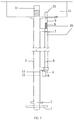
- FIG. 1 is a structural diagram of a loading platform for rock mechanics test.
- FIG. 2 shows a relaxed or aligned state of an accurate limiting hole alignment device.
- FIG. 3 shows a contracted or aligning state of the accurate limiting hole alignment device.
- FIG. 4 is a side view of a master rod.
- FIG. 5 is a front view of a stop sleeve.
- FIG. 6 is a 1-1 sectional view of a stop sleeve.
- FIG. 7 is a 2-2 sectional view of the stop sleeve.
- FIG. 8 is a vertical section of a secondary rod.
- FIG. 9 shows the loading platform with the threaded rod 17 rotated into a central threaded hole 21 at a lower end of a solid rigid column 13 in a triaxial chamber of the MTS rock mechanics test system.
- 1 horizontal cylindrical short rod
- 2 master rod
- 3 stop sleeve
- 4 lower end of secondary rod body
- 5 hole alignment sleeve
- 6 circular magnetic block
- 7 horizontal cylindrical pin
- 8 spring
- 9 secondary rod head body
- 10 rolling steel ball
- 11 upper scale line
- 12 lower scale line
- 13 solid rigid column
- 14 secondary rod
- 15 upper corbel
- 16 lower corbel
- 17 threaded rod
- 18 —smooth cylinder
- 19 smooth cylinder with a horizontal hole
- 20 secondary rod body
- 21 central threaded hole
- 22 peripheral limiting hole
- 23 sensor
- 24 limiting hole (location of steel pin)
- 25 horizontal hole.
- a loading platform for rock mechanics test comprises a master rod 2 , a secondary rod 14 , a stop sleeve 3 , a hole alignment sleeve 5 and related accessory members.
- the master rod 2 is configured to align with a central threaded hole 21
- the secondary rod 14 is configured to align with a limiting hole.
- the cylindrical stop sleeve 3 is sleeved on the master rod 2 to keep the master rod 2 and the secondary rod 14 in a horizontal level and a center-to-center distance therebetween equal to a center-to-center distance between the central threaded hole 21 and the peripheral limiting hole 22 .
- the rigid connection between the master rod 2 and the secondary rod 14 ensures that the master rod 2 and the secondary rod 14 are kept in a horizontal level and the center-to-center distance therebetween equals the center-to-center distance between the central threaded hole 21 and the peripheral limiting hole 22 .
- the stop sleeve 3 is provided with two corbel structures, i.e., an upper corbel 15 and a lower corbel 16 ; an end round hole axis of the upper corbel 15 coincides with an end round hole axis of the lower corbel 16 ; and the end round hole axis of the upper corbel 15 and the end round hole axis of the lower corbel 16 are parallel to the axis of the master rod 2 .
- a circular magnetic block 6 is fixed on the secondary rod 14 , the circular magnetic block 6 is configured to adsorb a hole alignment sleeve 5 sleeved on the secondary rod 14 ; an inner diameter of the hole alignment sleeve 5 equals an inner diameter of a steel pin in a limiting hole 24 arranged on the sensor 23 ; the hole alignment sleeve 5 are marked with a first scale line and a second scale line; and the first scale line corresponds to a relaxed or an aligned state, and the second scale line corresponds to a contracted or an aligning state.
- the master rod 2 is composed of a threaded rod 17 , a smooth cylinder 18 and a smooth cylinder 19 with a horizontal hole, the threaded rod 17 is capable of rotating into a threaded hole at a lower end of a solid rigid column 13 in a triaxial chamber of the test system, the smooth cylinder is arranged in the middle of the master rod 2 , and the stop sleeve 3 is sleeved on the smooth cylinder 18 .
- the master rod 2 is provided with a horizontal cylindrical short rod 1 , and the horizontal cylindrical short rod 1 runs through a round hole arranged on the smooth cylinder 19 with the horizontal hole of the master rod 2 ; and after the horizontal cylindrical short rod 1 is inserted into the round hole on the smooth cylinder 19 with the horizontal hole, the master rod 2 is capable of being rotated to rotate the threaded rod 17 into the threaded hole 21 at the lower end of the solid rigid column 13 in the triaxial chamber of the test system.
- the secondary rod 14 is composed of a secondary rod head body 9 and a secondary rod body 20 ;
- the secondary rod body 20 is a cylindrical rod;
- the secondary rod head body 9 is connected with the secondary rod body 20 by means of a spring 8 ;
- the secondary rod head body 9 arranged at an upper part of the secondary rod 14 is provided with a rolling steel ball 10 ;
- an outer diameter of the secondary rod head body 9 is lower than the inner diameter of the peripheral limiting hole 22 ;
- the secondary rod head body 9 is capable of inserting into the peripheral limiting hole 22 ;
- the secondary rod body 20 is fixed on the upper corbel 15 by means of a horizontal cylindrical pin 7 ;
- the body of the secondary rod 14 is a cylindrical rod;
- the secondary rod head body 9 arranged at the upper part of the secondary rod 14 is provided with a rolling steel ball 10 ;
- an outer diameter of the secondary rod head body 9 is lower than the inner diameter of the peripheral limiting hole 22 ;
- the secondary rod head body 9 is capable of inserting into the peripheral
- FIG. 2 shows a relaxed or the aligned state of an accurate limiting hole alignment device.
- the lower end of the secondary rod body 4 is pointed at the upper scale line 11 , the term “relaxed” means that the secondary rod 14 is retractable freely and the term “aligned” means that the secondary rod body 9 is inserted into the peripheral limiting hole 22 at a lower end of the solid rigid column 13 .
- the spring 8 is free and the length thereof is equal to original length thereof; and at the aligned state, the spring 8 is subject to deformation but is not locked in position, thus the length thereof is smaller than the original length thereof.
- FIG. 3 shows a contracted or the aligning state of the accurate limiting hole alignment device.
- the secondary rod body 4 is pointed at the lower scale line 12 , the term “contracted” means that the secondary rod is retracted to withdraw the rod head from the peripheral limiting hole 22 at the lower end of the solid rigid column 13 after alignment; and the term “aligning” means that the secondary rod aligns with the peripheral limiting hole 22 during rotation of the sleeve after the threaded rod section of the master rod is inserted into the central threaded hole 21 at the lower end of the solid rigid column 13 .
- the spring 8 At the contracted state, the spring 8 is subject to elastic deformation that shortens the length thereof, thus the length of the spring 8 is smaller than the original length thereof at this time, and the spring is capable of being pushed out of the peripheral limiting hole 22 ; at the aligning state, the spring 8 is locked in position and is subject to the maximum elastic deformation, thus the length of the spring 8 is smaller than the original length thereof; and the maximum deformation maintained in the aligning process of the spring 8 is conducive to reducing torsional deformation of the spring 8 , decreasing displacement of the secondary rod head body 9 in the aligning process and improving aligning accuracy.
- the master rod 2 is provided with the horizontal cylindrical short rod 1 , and the horizontal cylindrical short rod 1 runs through a round hole arranged on the smooth cylinder 19 with the horizontal hole of the master rod 2 ; after the horizontal cylindrical short rod 1 is inserted into the round hole on the smooth cylinder 19 with the horizontal hole, the master rod 2 is capable of being rotated to rotate the threaded rod 17 into the threaded hole at the lower end of the solid rigid column 13 in the triaxial chamber of the test system; and the horizontal cylindrical short rod 1 provides a point of external force application when the threaded rod 17 of the master rod 2 is rotated into the threaded hole.
- the stop sleeve 3 is cylindrical and provided with two corbel structures, i.e., an upper corbel 15 and a lower corbel 16 ; the end round hole axis of the upper corbel 15 coincides with the end round hole axis of the lower corbel 16 ; and the end round hole axis of the upper corbel 15 and the end round hole axis of the lower corbel 16 are parallel to the axis of the master rod 2 .
- the master rod 2 and the secondary rod 14 are kept in a horizontal level, with the center-to-center distance therebetween equal to the center-to-center distance between the central threaded hole 21 and the peripheral limiting hole 22 ; the end round hole axis of the upper corbel 15 coincides with the end round hole axis of the lower corbel 16 ; and the end round hole axes of the upper corbel 15 and the lower corbel 16 are parallel to the axis of the master rod 2 .
- the secondary rod 14 is composed of the secondary rod head body 9 and the secondary rod body 20 ; the secondary rod head body 9 is provided with the rolling steel ball 10 ; the outer diameter of the secondary rod head body 9 is lower than the inner diameter of the peripheral limiting hole 22 ; and the horizontal cylindrical pin 7 is arranged on the secondary rod body 20 .
Landscapes
- Physics & Mathematics (AREA)
- Health & Medical Sciences (AREA)
- Life Sciences & Earth Sciences (AREA)
- Chemical & Material Sciences (AREA)
- Analytical Chemistry (AREA)
- Biochemistry (AREA)
- General Health & Medical Sciences (AREA)
- General Physics & Mathematics (AREA)
- Immunology (AREA)
- Pathology (AREA)
- Investigating Strength Of Materials By Application Of Mechanical Stress (AREA)
- Force Measurement Appropriate To Specific Purposes (AREA)
Abstract
Description
Claims (6)
Applications Claiming Priority (2)
| Application Number | Priority Date | Filing Date | Title |
|---|---|---|---|
| CN201810403204.8 | 2018-04-28 | ||
| CN201810403204.8A CN108489804A (en) | 2018-04-28 | 2018-04-28 | MTS pilot system high-temperature high pressure sensor the service of connection devices |
Publications (2)
| Publication Number | Publication Date |
|---|---|
| US20190331567A1 US20190331567A1 (en) | 2019-10-31 |
| US11215540B2 true US11215540B2 (en) | 2022-01-04 |
Family
ID=63313352
Family Applications (1)
| Application Number | Title | Priority Date | Filing Date |
|---|---|---|---|
| US16/396,790 Expired - Fee Related US11215540B2 (en) | 2018-04-28 | 2019-04-29 | Loading platform for rock mechanics test |
Country Status (2)
| Country | Link |
|---|---|
| US (1) | US11215540B2 (en) |
| CN (1) | CN108489804A (en) |
Families Citing this family (4)
| Publication number | Priority date | Publication date | Assignee | Title |
|---|---|---|---|---|
| CN111307606B (en) * | 2020-04-07 | 2024-05-14 | 四川大学 | Deep high-temperature high-pressure environment rock stretching and pulling-pressing cyclic mechanics experimental device |
| CN113138116B (en) * | 2021-04-01 | 2022-04-08 | 北京科技大学 | A rigid-flexible rock pressure testing machine device for teaching demonstration |
| CN113262031B (en) * | 2021-06-28 | 2023-03-24 | 宁波兆盈医疗器械有限公司 | Tibial intramedullary nail distal hole aiming gauge and use method thereof |
| CN115728128B (en) * | 2022-11-16 | 2025-11-14 | 芜湖富春染织股份有限公司 | A yarn elastic tension testing frame with a positioning clamp assembly |
Citations (5)
| Publication number | Priority date | Publication date | Assignee | Title |
|---|---|---|---|---|
| CN106018059A (en) * | 2016-05-23 | 2016-10-12 | 中国矿业大学 | Test device and method applicable to rock and capable of realizing principal stress axis rotation |
| CN106248487A (en) * | 2016-09-28 | 2016-12-21 | 中国科学院武汉岩土力学研究所 | A kind of rock true triaxial test equipment |
| CN106989986A (en) * | 2017-03-29 | 2017-07-28 | 西安近代化学研究所 | Explosive loading responds stress test sensor locator |
| CN107014672A (en) * | 2017-03-31 | 2017-08-04 | 重庆大学 | Loaded coal rock body heat fluid structurecoupling CT triaxial pressure loading systems |
| CN107063882A (en) * | 2017-05-15 | 2017-08-18 | 四川大学 | A kind of Rock Mechanics Test system for simulating deep ground environment |
Family Cites Families (6)
| Publication number | Priority date | Publication date | Assignee | Title |
|---|---|---|---|---|
| CN202088169U (en) * | 2011-03-10 | 2011-12-28 | 浙江吉利汽车研究院有限公司 | Installation fixture for vibration acceleration transducer |
| CN103616295B (en) * | 2013-12-10 | 2015-08-05 | 山东科技大学 | A kind of non-standard rock sample bar mechanics parameter testing device and method of testing |
| CN103963009B (en) * | 2014-01-17 | 2016-04-27 | 宁波吉利罗佑发动机零部件有限公司 | A kind of specific purpose tool of disassembling sensor |
| CN205103090U (en) * | 2015-11-19 | 2016-03-23 | 长春市科意试验仪器有限公司 | Pressure chamber structure of rock mechanics triaxial compression test machine |
| CN205103102U (en) * | 2015-11-19 | 2016-03-23 | 长春市科意试验仪器有限公司 | A triaxial compression test machine for rock test |
| CN205218995U (en) * | 2015-12-21 | 2016-05-11 | 杭州电力设备制造有限公司 | Assembling tool |
-
2018
- 2018-04-28 CN CN201810403204.8A patent/CN108489804A/en active Pending
-
2019
- 2019-04-29 US US16/396,790 patent/US11215540B2/en not_active Expired - Fee Related
Patent Citations (5)
| Publication number | Priority date | Publication date | Assignee | Title |
|---|---|---|---|---|
| CN106018059A (en) * | 2016-05-23 | 2016-10-12 | 中国矿业大学 | Test device and method applicable to rock and capable of realizing principal stress axis rotation |
| CN106248487A (en) * | 2016-09-28 | 2016-12-21 | 中国科学院武汉岩土力学研究所 | A kind of rock true triaxial test equipment |
| CN106989986A (en) * | 2017-03-29 | 2017-07-28 | 西安近代化学研究所 | Explosive loading responds stress test sensor locator |
| CN107014672A (en) * | 2017-03-31 | 2017-08-04 | 重庆大学 | Loaded coal rock body heat fluid structurecoupling CT triaxial pressure loading systems |
| CN107063882A (en) * | 2017-05-15 | 2017-08-18 | 四川大学 | A kind of Rock Mechanics Test system for simulating deep ground environment |
Non-Patent Citations (5)
| Title |
|---|
| CN106018059A—pre (Year: 2016). * |
| CN106248487A—preview (Year: 2016). * |
| CN106989986A—PRE (Year: 2017). * |
| CN-107014672-A-English (Year: 2017). * |
| CN107063882A—preview (Year: 2017). * |
Also Published As
| Publication number | Publication date |
|---|---|
| CN108489804A (en) | 2018-09-04 |
| US20190331567A1 (en) | 2019-10-31 |
Similar Documents
| Publication | Publication Date | Title |
|---|---|---|
| US11215540B2 (en) | Loading platform for rock mechanics test | |
| US10704998B2 (en) | Rock mechanics response test system for simulated complex deep earth environment | |
| US10823653B2 (en) | Rock damage mechanics test system for high temperature and high pressure deep earth environment | |
| CN204630859U (en) | 4.5 joules of high strength concrete resiliometers | |
| CN103954496A (en) | Direct tension test testing device for high-freedom degree fragile material and a testing method based on device | |
| CN209264474U (en) | A kind of laser-calibrated reisilometer | |
| CN109104909B (en) | Missile Adapter Static Pressure Test Device | |
| CN205209615U (en) | Controllable formula aircraft weighting device | |
| CN116181385B (en) | Anchor rod yield and prestress monitoring integrated device and its use method | |
| CN215677826U (en) | Detection auxiliary device of concrete resiliometer | |
| CN210979200U (en) | Stable placing rack for environment detection equipment | |
| CN209068093U (en) | A kind of bracket of mapping equipment | |
| CN103575191A (en) | Testing device for foundation model test failure surface | |
| CN205342902U (en) | A fixture for accurate bar -shaped thing | |
| CN105783671B (en) | A large-size ring body sealing surface roundness calibration device | |
| CN211292416U (en) | Resilience instrument for supervision | |
| CN108593171A (en) | MTS triaxial test force sensor apparatus | |
| CN112729738A (en) | Double-table vibration test device | |
| CN108051186B (en) | A kind of optical mirror slip anti-strike ability test device | |
| CN221925922U (en) | Rock mass point load detector | |
| CN208620944U (en) | A kind of alley center height measuring device | |
| CN206832573U (en) | Workpiece adjustment mechanism for Shore hardness detection | |
| CN222733497U (en) | Pile hole diameter detection device | |
| CN222087013U (en) | A kind of engineering measurement benchmark device | |
| CN221839380U (en) | Meteorological pole capable of realizing rigid angle locking |
Legal Events
| Date | Code | Title | Description |
|---|---|---|---|
| FEPP | Fee payment procedure |
Free format text: ENTITY STATUS SET TO UNDISCOUNTED (ORIGINAL EVENT CODE: BIG.); ENTITY STATUS OF PATENT OWNER: SMALL ENTITY |
|
| AS | Assignment |
Owner name: SICHUAN UNIVERSITY, CHINA Free format text: ASSIGNMENT OF ASSIGNORS INTEREST;ASSIGNORS:WEI, YUFENG;LIU, JIANFENG;WANG, LU;AND OTHERS;SIGNING DATES FROM 20190420 TO 20190421;REEL/FRAME:049326/0071 Owner name: CHENGDU UNIVERISITY OF TECHNOLOGY, CHINA Free format text: ASSIGNMENT OF ASSIGNORS INTEREST;ASSIGNORS:WEI, YUFENG;LIU, JIANFENG;WANG, LU;AND OTHERS;SIGNING DATES FROM 20190420 TO 20190421;REEL/FRAME:049326/0071 |
|
| FEPP | Fee payment procedure |
Free format text: ENTITY STATUS SET TO SMALL (ORIGINAL EVENT CODE: SMAL); ENTITY STATUS OF PATENT OWNER: SMALL ENTITY |
|
| STPP | Information on status: patent application and granting procedure in general |
Free format text: DOCKETED NEW CASE - READY FOR EXAMINATION |
|
| STPP | Information on status: patent application and granting procedure in general |
Free format text: NON FINAL ACTION MAILED |
|
| STPP | Information on status: patent application and granting procedure in general |
Free format text: RESPONSE TO NON-FINAL OFFICE ACTION ENTERED AND FORWARDED TO EXAMINER |
|
| STPP | Information on status: patent application and granting procedure in general |
Free format text: EX PARTE QUAYLE ACTION MAILED |
|
| STPP | Information on status: patent application and granting procedure in general |
Free format text: NOTICE OF ALLOWANCE MAILED -- APPLICATION RECEIVED IN OFFICE OF PUBLICATIONS |
|
| STPP | Information on status: patent application and granting procedure in general |
Free format text: PUBLICATIONS -- ISSUE FEE PAYMENT RECEIVED |
|
| STPP | Information on status: patent application and granting procedure in general |
Free format text: PUBLICATIONS -- ISSUE FEE PAYMENT VERIFIED |
|
| STCF | Information on status: patent grant |
Free format text: PATENTED CASE |
|
| FEPP | Fee payment procedure |
Free format text: MAINTENANCE FEE REMINDER MAILED (ORIGINAL EVENT CODE: REM.); ENTITY STATUS OF PATENT OWNER: SMALL ENTITY |
|
| LAPS | Lapse for failure to pay maintenance fees |
Free format text: PATENT EXPIRED FOR FAILURE TO PAY MAINTENANCE FEES (ORIGINAL EVENT CODE: EXP.); ENTITY STATUS OF PATENT OWNER: SMALL ENTITY |
|
| STCH | Information on status: patent discontinuation |
Free format text: PATENT EXPIRED DUE TO NONPAYMENT OF MAINTENANCE FEES UNDER 37 CFR 1.362 |
|
| FP | Lapsed due to failure to pay maintenance fee |
Effective date: 20260104 |