US11215522B2 - Apparatus and method for testing pressure sensor and display device using the same - Google Patents
Apparatus and method for testing pressure sensor and display device using the same Download PDFInfo
- Publication number
- US11215522B2 US11215522B2 US16/285,071 US201916285071A US11215522B2 US 11215522 B2 US11215522 B2 US 11215522B2 US 201916285071 A US201916285071 A US 201916285071A US 11215522 B2 US11215522 B2 US 11215522B2
- Authority
- US
- United States
- Prior art keywords
- mounting portion
- pressure
- display device
- stage
- pressing
- Prior art date
- Legal status (The legal status is an assumption and is not a legal conclusion. Google has not performed a legal analysis and makes no representation as to the accuracy of the status listed.)
- Active, expires
Links
Images


Classifications
-
- G—PHYSICS
- G06—COMPUTING OR CALCULATING; COUNTING
- G06F—ELECTRIC DIGITAL DATA PROCESSING
- G06F11/00—Error detection; Error correction; Monitoring
- G06F11/22—Detection or location of defective computer hardware by testing during standby operation or during idle time, e.g. start-up testing
- G06F11/2205—Detection or location of defective computer hardware by testing during standby operation or during idle time, e.g. start-up testing using arrangements specific to the hardware being tested
- G06F11/2221—Detection or location of defective computer hardware by testing during standby operation or during idle time, e.g. start-up testing using arrangements specific to the hardware being tested to test input/output devices or peripheral units
-
- G—PHYSICS
- G01—MEASURING; TESTING
- G01L—MEASURING FORCE, STRESS, TORQUE, WORK, MECHANICAL POWER, MECHANICAL EFFICIENCY, OR FLUID PRESSURE
- G01L25/00—Testing or calibrating of apparatus for measuring force, torque, work, mechanical power, or mechanical efficiency
-
- G—PHYSICS
- G01—MEASURING; TESTING
- G01G—WEIGHING
- G01G23/00—Auxiliary devices for weighing apparatus
- G01G23/01—Testing or calibrating of weighing apparatus
-
- G—PHYSICS
- G01—MEASURING; TESTING
- G01G—WEIGHING
- G01G23/00—Auxiliary devices for weighing apparatus
- G01G23/18—Indicating devices, e.g. for remote indication; Recording devices; Scales, e.g. graduated
- G01G23/36—Indicating the weight by electrical means, e.g. using photoelectric cells
- G01G23/37—Indicating the weight by electrical means, e.g. using photoelectric cells involving digital counting
- G01G23/3707—Indicating the weight by electrical means, e.g. using photoelectric cells involving digital counting using a microprocessor
- G01G23/3721—Indicating the weight by electrical means, e.g. using photoelectric cells involving digital counting using a microprocessor with particular representation of the result, e.g. graphic
-
- G—PHYSICS
- G01—MEASURING; TESTING
- G01M—TESTING STATIC OR DYNAMIC BALANCE OF MACHINES OR STRUCTURES; TESTING OF STRUCTURES OR APPARATUS, NOT OTHERWISE PROVIDED FOR
- G01M99/00—Subject matter not provided for in other groups of this subclass
- G01M99/008—Subject matter not provided for in other groups of this subclass by doing functionality tests
-
- G—PHYSICS
- G06—COMPUTING OR CALCULATING; COUNTING
- G06F—ELECTRIC DIGITAL DATA PROCESSING
- G06F11/00—Error detection; Error correction; Monitoring
- G06F11/22—Detection or location of defective computer hardware by testing during standby operation or during idle time, e.g. start-up testing
- G06F11/2273—Test methods
-
- G—PHYSICS
- G06—COMPUTING OR CALCULATING; COUNTING
- G06F—ELECTRIC DIGITAL DATA PROCESSING
- G06F11/00—Error detection; Error correction; Monitoring
- G06F11/22—Detection or location of defective computer hardware by testing during standby operation or during idle time, e.g. start-up testing
- G06F11/26—Functional testing
- G06F11/273—Tester hardware, i.e. output processing circuits
-
- G—PHYSICS
- G06—COMPUTING OR CALCULATING; COUNTING
- G06F—ELECTRIC DIGITAL DATA PROCESSING
- G06F3/00—Input arrangements for transferring data to be processed into a form capable of being handled by the computer; Output arrangements for transferring data from processing unit to output unit, e.g. interface arrangements
- G06F3/01—Input arrangements or combined input and output arrangements for interaction between user and computer
- G06F3/03—Arrangements for converting the position or the displacement of a member into a coded form
- G06F3/041—Digitisers, e.g. for touch screens or touch pads, characterised by the transducing means
- G06F3/0416—Control or interface arrangements specially adapted for digitisers
- G06F3/0418—Control or interface arrangements specially adapted for digitisers for error correction or compensation, e.g. based on parallax, calibration or alignment
-
- G—PHYSICS
- G06—COMPUTING OR CALCULATING; COUNTING
- G06F—ELECTRIC DIGITAL DATA PROCESSING
- G06F3/00—Input arrangements for transferring data to be processed into a form capable of being handled by the computer; Output arrangements for transferring data from processing unit to output unit, e.g. interface arrangements
- G06F3/14—Digital output to display device ; Cooperation and interconnection of the display device with other functional units
Definitions
- the present disclosure relates to an apparatus and method of testing a pressure sensor, and a display device using the same.
- a display device for displaying an image is used for various electronic appliances for providing an image to a user, such as smartphones, tablet personal computers (PCs), digital cameras, notebook computers, navigators, and televisions.
- the display device includes a display panel for generating and displaying an image and can incorporate various input devices therein.
- a touch panel recognizing a touch input has been widely applied to a display device.
- the touch panel has a trend to replace existing physical input devices such as a keypad and a mouse because of the convenience of touching directly on the surface of the display device.
- Recent research focuses on implementing a touch panel capable of detecting various other input signals, for example, by mounting a pressure sensor on a display device in addition to the touch panel.
- a conventional testing method in which a weight is placed on a display panel and then the self-weight thereof is used has been advantageous in that a test can be performed by only the weight.
- this method is applied to a display device provided with an enlarged display panel having a curved portion, an accurate test could not be performed because a weight may move or run down on the curved surface of the display panel. Therefore, an apparatus for testing an operation and sensitivity of a pressure sensor disposed on the curved portion of a display device is required.
- An aspect of the present disclosure is to provide a test apparatus for testing operation and correcting sensitivity of a pressure sensor that may be disposed on a curved portion of a display panel.
- Another aspect of the present disclosure is to provide a method of testing operation and correcting sensitivity of a pressure sensor by using the test apparatus.
- Still another aspect of the present disclosure is to provide a display device in which the sensitivity of a pressure sensor is corrected based on test results obtained from the test apparatus.
- a test apparatus includes: a stage having a planar surface extending in a first direction and a second direction crossing the first direction; a mounting portion disposed on the stage to place a test member thereon; an angle adjusting portion adjusting a first angle of the mounting portion to incline the mounting portion with respect to the planar surface of the stage; and a pressing guide disposed on the stage and moving a pressing member in the first direction, the second direction, and a third direction normal to the planar surface of the stage.
- the test member may be a display device including a flat portion and at least one curved portion extending from the flat portion, and wherein the at least one curved portion is provided with at least one pressure sensor.
- the pressing member may press the at least one curved portion of the display device.
- the pressing guide may include: a rail moving the pressing member in the first direction; a first slide member engaged with the rail and moving the pressing member in the third direction; and a second slide member engaged with the first slide member and moving the pressing member in the second direction.
- the test apparatus may further include: a guide arm engaged with the second slide member and supporting the pressing member, wherein the guide arm is provided with a guide ring capable of removably attaching the pressing member.
- the guide arm may be provided as a pair of guide arms, and the pair of guide arms is disposed to overlap each other in the third direction and be spaced apart from each other by a predetermined distance.
- the test apparatus may further include: an anti-slip member disposed on an upper surface of the mounting portion and preventing the test member from slipping when the mounting portion is inclined by the angle adjusting portion at the first angle.
- the angle adjusting portion may be engaged with the mounting portion along a long side of the mounting portion to incline the mounting portion, the first angle ranges between 0° and 360°, and the angle adjusting portion includes a support member supporting the test member placed on the mounting portion.
- the test apparatus may further include: a rotating member rotating the mounting portion about an axis extending in the third direction to adjust a second angle between the mounting portion and the stage.
- the test apparatus may further include: at least one support member supporting one side of the test member when the mounting portion is inclined at the first angle by the angle adjusting portion, and the at least one support member is disposed on one side of the mounting portion.
- the pressing member may include a body and a protrusion that protrudes from a surface of the body.
- the protrusion is engaged with a pressing cover that covers the protrusion.
- a cross-section of the pressing cover may be any one of a concave center shape, a convex center shape, and a shape having a flat side on one end and a convex side on an opposite end.
- a test method includes: placing a test member on a mounting portion; adjusting an inclined angle of the mounting portion using an angle adjusting portion; adjusting a position of a pressing guide to correspond to a measurement position of the test member; pressing the test member using a pressing member of the pressing guide; and transmitting pressure information measured from the test member to an external appliance and displaying the pressure information.
- the test member may be a display device including a flat portion and at least one curved portion extending from the flat portion, and the at least one curved portion is provided with at least one pressure sensor.
- the inclined angle of the mounting portion may be adjusted such that the pressing member vertically presses the curved portion of the display device.
- amounts of pressure applied to the test member may be sequentially changed, operation time of the test member may be checked, and a pressure threshold value at which the test member operates may be recorded on a storage.
- a display device includes: a display panel including a flat portion and at least one curved portion extending from the flat portion; at least one pressure sensor disposed on the at least one curved portion and including a plurality of pressure sensing cells; a storage storing a pressure threshold value of the at least one pressure sensing cells, the pressure threshold values being measured by an external test apparatus; and a controller receiving pressure values sensed from the plurality of pressure sensing cells of the at least one pressure sensor, wherein the controller compares the pressure values the pressure threshold value and determines whether or not a pressure is applied to the display device.
- the controller may display on the display panel a window indicating to re-measure the pressure values when a predetermined condition is satisfied.
- the predetermined condition may be any one of a case where a pressure exceeding a predetermined range is applied to the display device in comparison with the pressure threshold value, a case where a predetermined period expires, and a case where a pressure is applied to the at least one pressure sensor more than a predetermined number of times.
- FIG. 1 is a perspective view of a test apparatus for testing a display device according to an embodiment
- FIG. 2 is a side view of a test apparatus for testing a display device according to an embodiment
- FIG. 3 is a perspective view of a guide arm according to an embodiment
- FIG. 4 is a perspective view of various pressing covers and a perspective view showing a state in which the pressing member is engaged with one of the pressing covers according to an embodiment
- FIG. 5 is a side view of a pressing cover having a rectangular parallelepiped shape and a side view showing a state in which the pressing member is engaged with the pressing cover according to one embodiment
- FIG. 6 is a perspective view showing a case where a display device is placed on a mounting portion included in an angle guide according to an embodiment
- FIG. 7 is a cross-sectional view showing a case where a display device is placed on a mounting portion according to an embodiment
- FIG. 8 is a side view of an angle guide according to an embodiment
- FIG. 9 is a perspective view of various supports according to an embodiment
- FIG. 10 is a perspective view showing a case where a display device is placed on a mounting portion included in an angle guide according to another embodiment
- FIG. 11 is a cross-sectional view showing a case where a display device is placed on a mounting portion according to another embodiment
- FIG. 12 is a side view of an angle guide according to another embodiment
- FIG. 13 is a perspective view showing a pressure sensor mounted on a display device according to an embodiment
- FIG. 14 is a diagram sequentially showing a method of testing a display device using a test apparatus according to an embodiment
- FIG. 15 is a conceptual view showing a method of testing a pressure sensor included in a display device using a test apparatus according to an embodiment
- FIG. 16 is a diagram showing a method of processing pressure value information measured through a pressure sensor according to an embodiment
- FIG. 17 is a flowchart showing a process of correcting a sensitivity deviation of a plurality of pressure sensors having different sensitivities
- FIG. 18 is a perspective view of a display device according to an embodiment
- FIG. 19 is an exploded perspective view of a display device according to an embodiment
- FIG. 20 is a plan view showing a first pressure sensor and first bumps according to an embodiment
- FIG. 21 a plan view showing a second pressure sensor and second bumps according to an embodiment
- FIG. 22 is a plan view showing an area of FIG. 21 in detail
- FIG. 23 is a cross-sectional view showing an example of II-IT of FIG. 22 ;
- FIG. 24 is a cross-sectional view showing an example of a display device.
- first, second, etc. may be used herein to describe various elements, components, regions, layers, and/or, sections, these elements, components, regions, layers, and/or, sections should not be limited by these terms. These terms are used merely to distinguish one element, component, region, layer, and/or, section from another element, component, region, layer, and/or, section. Thus, a first element, component, region, layer, and/or, section discussed below could be termed a second element, component, region, layer, and/or, section without departing from the teachings of the present disclosure.
- FIG. 1 is a perspective view of a test apparatus for testing a display device according to an embodiment
- FIG. 2 is a side view of a test apparatus for testing a display device according to an embodiment.
- a test apparatus 1 for testing a display device 1000 includes a stage 10 , a pressing guide including first, second, and third slide members 20 , 30 , 40 , and a guide arm 50 , a pressing member 60 , and an angle guide 70 .
- the stage 10 may include one or more rails RL extending from one side to the other side.
- the rails RL may include one or more linear motion (LM) guides such that the pressing guide can move precisely over the stage 10 .
- LM linear motion
- a ruler (not shown) may be provided on the stage 10 to accurately measure and confirm Y-axis coordinates. Thus, a test for the same point of the display device 1000 may be accurately and repeatedly performed.
- the pressing guide may include a first slide member 20 that is vertically formed on the stage 10 and engaged with the rails RL to be movable along the Y-axis, a second slide member 30 that is engaged with the first slide member 20 to be movable along the Z-axis, and a third slide member 40 that is engaged with the second slide member 30 to be movable along the X-axis.
- the first slide member 20 may include a Z-axis slider supporting portion 22 and one or more Y-axis slider portions 21 .
- the Z-axis slider supporting portion 22 may be disposed on one side of the first slide member 20 and may have the same structure as the rails RL disposed on the stage 10 .
- the Z-axis slider supporting portion 22 may include one or more second linear motion (LM) guides such that the second slide member 30 can move precisely up and down along the Z-axis direction.
- a ruler (not shown) may be provided around the Z-axis slider supporting portion 22 to accurately measure and confirm Y-axis coordinates. Thus, the test for the same point of the display apparatus 1000 may be accurately and repeatedly performed.
- the Y-axis slider portions 21 may be disposed on a lower surface of the first slide member 20 , and may be engaged with the rails RL to move back and forth along the Y-axis direction.
- the second slide member 30 may include an X-axis slider supporting portion 32 and a Z-axis slider portion 31 .
- the X-axis slider supporting portion 32 may be disposed on an upper surface of the second slide member 30 and may have the same structure as the rails RL disposed on the stage 10 .
- the X-axis slider supporting portion 32 may include one or more third linear motion (LM) guides such that the second slide member 30 can move precisely along the X-axis.
- LM linear motion
- a ruler (not shown) may be provided around the X-axis slider supporting portion 32 to accurately measure and confirm X-axis coordinates. Thus, the test for the same point of the display apparatus 1000 may be accurately and repeatedly performed.
- the X-axis slider supporting portion 32 may include first and second X-axis slider supporting portions 32 overlapping each other in the Z-axis direction.
- the first and second X-axis slider supporting portions may be disposed at a predetermined distance along the Z-axis direction.
- the Z-axis slider portion 31 may be disposed on one side of the first slide member 20 , and may be engaged with the Z-axis slider supporting portion 22 of the first slide member 20 to move up and down along the Z-axis direction.
- the third slide member 40 may include a guide arm fixing portion and an X-axis slider portion.
- the guide arm fixing portion may be disposed on an upper surface of the third slide member 40 , and may include at least one screw groove to be engaged with the guide arm 50 through a screw connection.
- the X-axis slider portion may be disposed on a lower surface of the third slide member 40 , and may be engaged with the X-axis slider supporting portion 32 disposed on the upper surface of the second slide member 30 to move back and forth along the X-axis direction.
- the third slider member 40 may include first and second slider portions 40 that are respectively engaged with the first and second X-axis slider supporting portions 32 .
- the aforementioned first slide member 20 may further include a fixing member 23 for holding an adjusted position.
- Each of the second slide member 30 and the third slide member 40 may also include a fixing member (not shown) for holding an adjusted position.
- FIG. 3 is a perspective view of a guide arm according to an embodiment.
- the guide arm 50 may include a slider fixing portion 51 and a guide ring 52 .
- the slider fixing portion 51 may be disposed on one side of the guide arm 50 and may include at least one screw groove 53 .
- four screw grooves 53 may be provided.
- a square-shaped rim may be formed.
- the screw grooves 53 may be formed through the guide arm 50 to overlap the screw grooves that are formed in the guide arm fixing portion of the third slide member 40 in the Z-axis direction.
- the guide ring 52 may be disposed on the other side of the guide arm 50 .
- the guide ring 52 may have a planar circular shape (or a hollow disk shape).
- the present disclosure is not limited thereto, and the planar shape of the guide ring 52 may be changed depending on the planar shape of the pressing member 60 .
- the planar shape of the pressing member 60 is a square shape or a regular octagonal shape
- the planar shape of the guide ring 52 may also be a square shape or a regular octagonal shape correspondingly.
- the pressing member 60 may be referred to as a weight made of a metal.
- the planar area of the guide ring 52 may be larger than the planar area of the pressing member 60 .
- the pressing member 60 may be inserted obliquely such that the display device 1000 and the pressing member 60 may be in an oblique contact with each other, and resultantly, a pressure of the pressing member 60 applied to the display device 1000 may be distorted.
- the planar area of the guide ring 52 is substantially equal to the planar area of the pressing member 60 , the influence of the pressing member 60 being supported by the guide ring 52 may increase, but a pressure of the pressing member 60 applied to the display device 1000 may still be distorted.
- the guide arm 50 may include two or more guide arms.
- the guide arm 50 includes first and second guide arms 50 that are respectively coupled to the first and second slide members 40 of the third slide member 40 .
- the volume of the pressing member 60 increases in proportion to its weight.
- the pressing member 60 having a large volume and supported through the aforementioned first and second guide arms 50 can reduce or prevent distortion of a pressure of the pressing member 60 applied to the display device 1000 .
- FIG. 4 is a perspective view of various pressing cover and a perspective view showing a state in which the pressing member is engaged with one of the pressing covers according to an embodiment.
- FIG. 5 is a perspective view of a pressing cover having a rectangular parallelepiped shape and a perspective view showing a state in which the pressing member is engaged with the pressing cover according to one embodiment.
- the pressing member 60 may be divided into a body 61 and a protrusion 62 .
- Both the body 61 and the protrusion 62 may have a cylindrical shape.
- the present disclosure is not limited thereto, and, for example, the shape of the pressing member 60 may be any one of a rectangular columnar and an octagonal columnar shape.
- the body 61 may be engaged with the aforementioned guide ring 52 of the guide arm 50 .
- the protrusion 62 may be engaged with each of the pressing covers CV 1 , CV 2 , CV 3 , and CV 4 .
- the diameter of the protrusion 62 may be smaller than the diameter of the body 61 , and the length of the protrusion 62 may be shorter than the length of the body 61 .
- the protrusion 62 may have a diameter of 5 mm and a length of 10 mm.
- the test apparatus 1 shown in FIGS. 1 and 2 may use various pressing members 60 having different weights to test the display device 1000 to apply various pressures to the display device 1000 .
- the pressing member 60 may be fabricated to have a constant weight difference, such as 200 g, 250 g, or 300 g, but the pressing member 60 may freely have any weight within the range of 10 gram to 1000 gram depending on the test application.
- Each of the pressing covers CV 1 , CV 2 , CV 3 , and CV 4 may be engaged with the protrusion 62 of the pressing member 60 to be brought into direct contact with the display device 1000 during the pressure testing.
- the pressing covers CV 1 , CV 2 , CV 3 , and CV 4 may include engaging portions H 1 , H 2 , H 3 , and H 4 (e.g., grooves) and contact portions, respectively.
- Each of the engaging portions H 1 , H 2 , H 3 , and H 4 is engaged with the protrusion 62 of the pressing member 60 to couple each of the pressing covers CV 1 , CV 2 , CV 3 , and CV 4 to the pressing member 60 .
- the contact portion that is brought into direct contact with a flat portion or a curved portion of the display device 1000 may have various shapes.
- a user's finger may be used to apply a pressure to pressure sensors 510 and 520 , which will be described later, of the display device 1000 .
- the user's finger that contacts the display device 1000 may include at least one of a concave portion, a convex portion, and a flat portion.
- each of the pressing covers CV 1 , CV 2 , CV 3 , and CV 4 may have a concave center (a), a convex center (b), or a shape (c) including one side that is flat and another side that is convex.
- the pressing covers CV 1 , CV 2 , CV 3 , and CV 4 may be made of a silicon material.
- some of the pressure sensors 510 and 520 disposed on a curved portion of the display device 1000 may have a length that occupies a portion (e.g., about 50%) of the display device 1000 .
- the diameter of the protrusion 62 may be smaller than the diameter of the body 61
- the diameter of each of the pressing covers CV 1 , CV 2 , CV 3 , and CV 4 engaged with the protrusions 62 may be smaller than the diameter of the body 61 . In this case, there may occur a problem that a pressure cannot be uniformly applied to the pressure sensors 510 and 520 .
- the pressing cover CV 4 may have a rectangular parallelepiped shape and may have a length corresponding to about 50% of the display panel 1000 .
- FIG. 6 is a perspective view showing a case where the display device 1000 is placed on a mounting portion included in an angle guide according to an embodiment
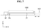
- FIG. 7 is a cross-sectional view showing a case where the display device 1000 is placed on a mounting portion according to an embodiment
- FIG. 8 is a side view of an angle guide according to an embodiment
- FIG. 9 is a perspective view of various supports according to an embodiment.
- the angle guide 70 may include a pair of angle adjusting portions 72 and a mounting portion 71 .
- the pair of angle adjusting portions 72 may be a pair of plates having a predetermined thickness of a quadrant shape.
- the pair of angle adjusting portions 72 may be vertically formed on the stage 10 to face each other in the Y-axis direction.
- Each of the pair of angle adjusting portions 72 may include an opening OP (or an arc slot) formed along the outskirt of the quadrant and spaced apart from the outskirt by a predetermined distance.
- the periphery of the opening OP may include an indicator 76 that indicates an angle formed by an upper surface of the mounting portion 71 and an upper surface of the stage 10 .
- a test for the same point of the display device 1000 may be accurately and repeatedly performed.
- the angle formed by the upper surface of the mounting portion 71 and the upper surface of the stage 10 is in a range of 0° to 70°
- the present disclosure is not limited thereto.
- the angle formed by the upper surface of the mounting portion 71 and the upper surface of the stage 10 may be in a range of 0° to 90°.
- the mounting portion 71 may be a flat plate that supports the display device 1000 .
- the mounting portion 71 may be a rectangular plate.
- the surface area of the mounting portion 71 may be varied in proportion to the size of the display device 1000 to be mounted and tested.
- the mounting portion 71 may include a pin PN that extends in the Y-axis direction along one side surface of the mounting portion 71 and passes through holes formed in side surfaces of the pair of angle adjusting portions 72 .
- a handle 75 may be formed on one side of the mounting portion 71
- a fixing member 78 may be formed on the other side of the mounting portion 71 .
- the handle 75 of the mounting portion 71 may pass through the opening OP of one of the angle adjusting portions 72
- the fixing member 78 of the mounting portion 71 may pass through the opening OP of the other angle adjusting portion 72 .
- the fixing member 78 may include a bolt and a nut, each of which is provided with threads. Therefore, the mounting portion 71 can be lifted and rotated with respect to the longitudinal axis of the pin PN to adjust the angle formed by the upper surface of the display device 1000 and the upper surface of the stage 10 . After adjusting the angle of the mounting portion 71 to a desired angle, the display device may be fixed by using the fixing member 78 .
- the angle guide 70 may further include an anti-slip member 77 on the upper surface of the mounting portion 71 , and the display device 1000 may be placed directly on the surface of the anti-slip member 77 .
- the anti-slip member 77 may prevent the display device 1000 from slipping on the upper surface of the mounting portion 71 .
- the angle guide 70 may further include at least one support 73 .
- the support 73 may also be referred to as a support SP.
- the support 73 may support one side of the display device 1000 .
- the support 73 may securely place the display device 1000 preventing slip or displacement of the display device 1000 on the upper surface of the mounting portion 71 when the display device 1000 is rotated during the testing.
- the cross-sectional shape of the support 73 may have any one of a circle SP 1 , a square SP 2 , a regular octagon SP 3 , and a rectangle SP 4 in a plan view.
- the support 73 may make a point contact with one side of the display device 1000 .
- the support 73 may make a surface contact with one side of the display device 1000 .
- the support portion SP 4 When the support portion SP 4 has a sufficiently long transverse length, it is possible to make a surface contact with the one side of the display device 1000 entirely. In the case of a surface contact as compared to a point contact, a weight may be more evenly distributed. Thus, the user may proceed to test various situations as if the display device 1000 is gripped. For example, a situation where the user grips the display device 1000 with two fingers may be tested with the support portion SP 1 that has a circular shape in a plan view. Similarly, a situation where the user partially grips the display device 1000 with the palm of the hand may be tested with the rectangular support portion SP 4 that has a sufficiently long horizontal length.
- the support 73 may be made of various materials, for example, plastics such as acetal or metals such as aluminum.
- the mounting portion 71 of the angle guide 70 may further include an extendable holder HD 1 .
- the extendable holder HD 1 may include a damping rail RL.
- the extendable holder HD 1 may be disposed on the side surface of the mounting portion 71 opposite to the side surface where the pin PN is disposed to extend the mounting portion 71 , thereby increasing the size of the display device 1000 that can be firmly supported on the mounting portion 71 . Further, the height of the extendable holder HD 1 may be sufficient to support the display device 1000 . Thus, the extendable holder HD 1 may not be placed on the curved surface portion of the display device 1000 where the pressure sensors 510 and 520 are disposed.
- FIG. 10 is a perspective view showing a case where a display device is placed on a mounting portion included in an angle guide according to another embodiment
- FIG. 11 is a cross-sectional view showing a case where a display device is placed on a mounting portion according to another embodiment
- FIG. 12 is a side view of an angle guide according to another embodiment.
- an angle guide 70 _ 1 is different from the angle guide 70 in that a mounting portion 71 _ 1 is rotated with respect to a line having the same distance from one side surface and the other side surface of the mounting portion 71 _ 1 as a center axis to adjust the angle formed by the upper surface of the display device 1000 and the upper surface of a stage 10 _ 1 .
- the angle guide 70 _ 1 may further include a rotating member 79 capable of rotating 360° with respect to the Z-axis.
- the angle guide 70 _ 1 may include a pair of angle adjusting portions 72 _ 1 , the mounting portion 71 _ 1 , and the rotating member 79 .
- the pair of angle adjusting portions 72 _ 1 may be a pair of plates having a predetermined thickness of a circular shape and a flat bottom side.
- the pair of angle adjusting portions 72 _ 1 may be vertically formed on the stage 10 _ 1 to face each other in the Y-axis direction.
- Each of the pair of angle adjusting portions 72 _ 1 may include an opening OP_ 1 (or a circular slot) formed along the outskirt of the circle and spaced apart from the outskirt by a predetermined distance.
- the periphery of the opening OP_ 1 may include an indicator 76 _ 1 that indicates an angle formed by an upper surface of the mounting portion 71 _ 1 and an upper surface of the stage 10 _ 1 . Using the indicator 76 _ 1 , a test for the same point of the display device 1000 may be accurately and repeatedly performed.
- the opening OP_ 1 has a circular shape, the present disclosure is not limited thereto.
- the opening OP_ 1 may have a semi-circular shape.
- the mounting portion 71 _ 1 may be a flat plate that supports the display device 1000 .
- the mounting portion 71 _ 1 may be a rectangular plate.
- the surface area of the mounting portion 71 _ 1 may be varied in proportion to the size of the display device 1000 to be mounted and tested.
- the mounting portion 71 _ 1 may include a pin PN 1 that extends in the Y-axis direction through the center of the opening OP 1 .
- Each of the pair of angle adjusting portions 72 _ 1 may include a hole at the center to correspond to the pin PN 1 of the mounting portion 71 _ 1 .
- the pin PN 1 of the mounting portion 71 _ 1 is inserted into the holes of the pair of angle adjusting portions to rotatably engage the mounting portion 71 _ 1 and the angle adjusting portion 72 _ 1 with each other.
- a handle 75 _ 1 may be formed on one side of the mounting portion 71 _ 1
- a fixing member 78 _ 1 may be formed on the other side of the mounting portion 71 _ 1 .
- the handle 75 _ 1 of the mounting portion 71 _ 1 may pass through the opening OP 1 of one of the angle adjusting portions 72 _ 1
- the fixing member of the mounting portion 71 _ 1 may pass through the opening OP 1 of the other angle adjusting portion 72 _ 1 .
- the fixing member 78 _ 1 may include a bolt and a nut, each of which is provided with threads. Therefore, the angle guide 70 _ 1 can rotate the mounting portion 71 _ 1 with respect to the longitudinal axis of the pin PN 1 to adjust the angle formed by the upper surface of the display device 1000 and the upper surface of the stage 10 _ 1 . After adjusting the angle of the mounting portion 71 _ 1 to a desired angle, the display device 1000 may be fixed using the fixing member 78 _ 1 .
- the angle guide 70 _ 1 may further include an anti-slip member 77 _ 1 on the upper surface of the mounting portion 71 _ 1 , and the display device 1000 may be placed directly on the surface of the anti-slip member 77 _ 1 .
- the anti-slip member 77 _ 1 may prevent the display device 1000 from slipping on the upper surface of the mounting portion 71 _ 1 .
- the mounting portion 71 _ 1 of the angle guide 70 _ 1 may further include extendable holders HD 2 and HD 3 on both sides thereof.
- Each of the extendable holders HD 2 and HD 3 may include a damping rail RL.
- the extendable holders HD 2 and HD 3 may be disposed on both sides of the mounting portion 71 _ 1 to extend the mounting portion 71 _ 1 , thereby increasing the size of the display device 1000 that can be supported on the mounting portion 71 _ 1
- the display device 1000 may be firmly supported by the mounting portion 71 _ 1 even when the upper surface of the display device 1000 is turned upside down to face the upper surface of the stage 10 _ 1 .
- each of the holders HD 2 and HD 3 may be sufficient to support the display device 1000 .
- the extendable holders HD 2 and HD 3 may not be placed on the curved surface portion of the display device 1000 where the pressure sensors 510 and 520 are disposed.
- the pair of angle adjusting portions 72 _ 1 of the angle guide 70 _ 1 may be formed on a base BS disposed on the stage 10 _ 1 .
- the rotating member 79 may be included on the lower surface of the base BS.
- the rotating member 79 may engage the base BS and the stage 10 _ 1 with each other rotatably 360° in a plan view.
- the rotating member 79 having a shaft member at the center of the lower surface of the base BS may be disposed, and a shaft hole may be disposed at a portion of the stage 10 _ 1 to couple the shaft member to the base BS.
- the base BS may rotate 180° rotating the angle guide 70 _ 1 , and the mounting portion 71 _ 1 may ascend or descend without dismounting the display device 1000 from the mounting portion 71 _ 1 , thereby performing a test procedure on both sides of the display device 1000 .
- FIG. 13 is a perspective view showing a pressure sensor mounted on a display device according to an embodiment
- FIG. 14 is a diagram sequentially showing a method of testing a display device using a test apparatus according to an embodiment
- FIG. 15 is a conceptual view showing a method of testing a pressure sensor included in a display device using a test apparatus according to an embodiment.
- the display device 1000 may have a substantially rectangular shape with round edges in a plan view.
- the display device 1000 may have a rectangular planar shape having short sides in the first direction (e.g., the X-axis direction) and long sides in the second direction (e.g., the Y-axis direction).
- the edges where the short side in the first direction (X-axis direction) meets the long side in the second direction (Y-axis direction) may have a round shape of a predetermined curvature or a right angle shape.
- the planar shape of the display device 1000 is not limited to a rectangular shape, and may be formed in a polygonal shape, a circular shape, or an elliptical shape.
- the display device 1000 may include a first area DR 1 that has a flat planar shape and a second area DR 2 that extends from the left and right sides of the first area DR 1 .
- the second area DR 2 may be flat or curved.
- the angle formed by the first area DR 1 and the second area DR 2 may be an obtuse angle.
- the second area DR 2 may have a constant curvature or a variable curvature.
- the second area DR 2 extends from the left and right sides of the first area DR 1
- the present disclosure is not limited thereto. That is, the second area DR 2 may extend from only one of the left and right sides of the first area DR 1 .
- the second area DR 2 may extend from one or more of the upper and lower sides of the first area DR 1 as well as one or more of the left and right sides of the first area DR 1 .
- the second area DR 2 is disposed along the left and right edges of the display device 1000 will be described.
- the pressure sensor 520 may be formed of a plurality of pressure sensing cells.
- the plurality of pressure sensing cells may be disposed along the long side of the second direction (Y-axis direction).
- eight channels or eight pairs of pressure sensing cells may be formed to have a length corresponding to about 50% of the long side.
- the pressure sensor 520 may have an elongated shape.
- the eighth pressure sensing cell CE 8 may be disposed along the long side of the second direction (Y-axis direction), and one channel corresponding to the eighth pressure sensing cell CE 8 may be formed to have a length corresponding to about 50% of the long side.
- a second pressure sensor may be formed of a plurality of pressure sensing cells as well.
- the pressure sensors 510 and 520 may refer to the pressure sensors that are disposed along the left and right long sides of the display device 1000 in the length direction, and two or more channels (not shown) may be formed to have a length corresponding to about 50% of the long side.
- a method of testing a testing member includes the steps of: placing the test member on an angle guide 70 (S 10 ); adjusting an angle of the angle guide 70 (S 20 ); adjusting positions of pressing guide to correspond to measured positions of the testing member (S 30 ); engaging a pressing member 60 to the pressing guide and pressing the testing member (S 40 ); and measuring the pressure (S 50 ).
- the pressing guide may move to their respective zero point positions.
- the zero point position refers to a position where each of the first slide member 20 , the second slide member 30 , and the third slide member 40 is held to prevent the interference caused by the pressing guide in the process of placing the test member on the mounting portion 70 of the angle guide 70 .
- the first slide member 20 may be located at the left end in the Y-axis direction
- the second slide member 30 may be located at the uppermost end in the Z-axis direction
- the third slide member 40 may be located at the most rear end in the X-axis direction.
- the test member is placed on the mounting portion 71 of the angle guide 70 .
- the test member may be, for example, the display device 1000 .
- the display device 1000 may be located at the center of the mounting portion 71 .
- the angle guide 70 may include at least one support 73 . In this case, one side of the display device 1000 may be placed on the mounting portion 71 to directly contact the support 73 to support the display device 1000 .
- the angle guide 70 may include a pair of holders on both sides of the mounting portion 71 .
- the angle of the mounting portion 71 of the angle guide 70 is adjusted by rotating the angle guide 70 .
- the angle formed by the upper surface of the mounting portion 71 and the upper surface of the stage 10 may be adjusted such that a virtual tangent line to a cover glass of the display device 1000 is orthogonal to an imaginary longitudinal axis of the pressing member 60 .
- a user of the test apparatus 1 may adjust the angle using the handle 75 of the mounting portion 71 , and may fix the mounting portion 71 by tightening the nut of the fixing member 78 disposed on the opposite side.
- the pressing guide are adjusted such that the protrusion 62 of the pressing member 60 is located at a test position of the display device 1000 .
- the first slide member 20 may move left and right to adjust the Y-axis test position of the display device 1000
- the third slide member 40 may move up and down to adjust the Y-axis test position of the display device 1000 .
- the guide arm 50 may move in the downward direction (i.e., the Z-axis direction) such that the center of the guide ring 52 to be engaged to the pressing member 60 is located to overlap the target coordinate of the display device 1000 .
- one or more pressing members 60 may be inserted into the guide ring 52 to press the display device 1000 .
- the pressing members 60 corresponding to the interval of ⁇ 10% to +10% based on a magnitude of the pressure at which the pressure sensors 510 and 520 start to operate may be sequentially inserted in an order.
- the above range and interval of the pressing members 60 is not limited to this, and may be, for example, ⁇ 20% to +20% based on the magnitude of the pressure at which the pressure sensors 510 and 520 start to operate.
- the pressure is measured through the pressure sensors 510 and 520 .
- the weight correction according to the contact between the guide ring 52 and the pressing member 60 may be required.
- Weight correction may be performed by using the pressing member 60 that is weighted by the difference between the two measured weight values.
- FIG. 16 is a diagram showing a method of processing pressure value information measured through a pressure sensor according to an embodiment.
- the display device 1000 may transmit pressure measurement value information acquired through the pressure sensors 510 and 520 to an external appliance (S 51 ).
- the display device 1000 may internally process the pressure measurement value information.
- the display device 1000 may include a screen, a touch sensor, the pressure sensors 510 and 520 , a memory, a communication device, and a controller 710 .
- the communication device is configured to perform communication with various types of external appliances according to various communication protocols.
- the communication device may include a wireless communication chip, a Wi-Fi chip, a Bluetooth chip, a near-field communication (NFC) chip, and a Zigbee chip.
- the controller 710 may transmit the pressure measurement value information acquired by the pressure sensors 510 and 520 to the external appliance via the Bluetooth protocol.
- the communication protocol is not limited thereto, and other communication protocols such as Wi-Fi, NFC, and Zigbee may be used.
- the wireless communication chip refers to a chip that performs communication according to various communication standards such as IEEE, ZigBee, 3rd Generation (3G), 3rd Generation Partnership Project (3GPP), and Long Term Evolution (LTE).
- the NFC chip may operate in an NFC mode using a frequency band of 13.56 MHz among various RF-ID frequency bands such as 135 kHz, 13.56 MHz, 433 MHz, 860 to 960 MHz and 2.45 GHz.
- the external appliance may display the received pressure measurement value information on the screen (S 52 ).
- the pressure measurement information may be represented as a relative value to a reference value at which the pressure sensors 510 and 520 start to operate.
- the display device 1000 is pressed by the pressing member 60 having a weight of 250 gram to apply a pressure at which the pressure sensors 510 and 520 start to operate.
- the amount of pressure on the screen of the external appliance may be displayed as 80 .
- the magnitude of the pressure measured by the pressure sensors 510 and 520 is a 300 gram force
- the amount of pressure on the screen of the external appliance may be displayed as 120 .
- the controller 710 of the external appliance may display a result on the screen as to whether or not the respective pressure sensors 510 and 520 are normal.
- the controller 710 may determine whether the pressure sensors 510 and 520 operate normally when the controller 710 acquires a relative value corresponding to 90 to 110 as compared with the magnitude of the pressure at which the pressure sensors 510 and 520 start to operate, and may show the result in a window indicating a normal state.
- the controller 710 may determine whether the pressure sensors 510 and 520 operate abnormally when the controller 710 acquires a relative value not corresponding to 90 to 110 as compared with the magnitude of the pressure at which the pressure sensors 510 and 520 start to operate, and may show the result in a window indicating an abnormal state.
- the range of a normal operation is not limited thereto. For example, it may be determined that the pressure sensors 510 and 520 operate normally when the controller 710 acquires a relative value corresponding to 80 to 120 as compared with the magnitude of the pressure at which the pressure sensors 510 and 520 start to operate.
- the display device 1000 for storing pressure information obtained through the aforementioned method of testing the display device 1000 and correcting the pressure values sensed by the pressure sensors 510 and 520 will be described.
- the specific configuration of the display device 1000 will be described later, and for convenience, will be described using the following reference numerals.
- FIG. 17 is a flowchart showing a process of correcting a sensitivity deviation of a plurality of pressure sensors having different sensitivities.
- the process in which the controller 710 corrects the sensitivity deviation of the pressure sensors 510 and 520 includes the steps of: storing a pressure threshold value of the pressure sensors 510 and 520 measured by the test apparatus 1 of the display device 1000 (S 100 ); inputting the pressure values sensed by the pressure sensors 510 and 520 (S 200 ); comparing the pressure values with the pressure threshold value (S 300 ); and correcting an error for each of the pressure sensors 510 and 520 , for example, the sensitivity deviation for each of the plurality of pressure sensing cells included in the pressure sensor (S 400 ).
- the controller 710 may store the pressure threshold value obtained through the test apparatus 1 of the display device 1000 in a storage (S 100 ).
- the pressure threshold value may be defined as a magnitude of the pressure at which the pressure sensors 510 and 520 start to operate.
- the pressure threshold value may be obtained by detecting a pressure value at which the pressure sensors 510 and 520 start to operate, when the amount of the pressure applied to the display device 1000 is sequentially changed.
- the controller 710 may receive the pressure values sensed through the pressure sensors 510 and 520 (S 200 ).
- the respective pressure sensing cells may sense different amounts of pressure.
- the pressure sensing cell senses a relatively large amount of pressure as compared with the same pressure
- the pressure sensing cell may be referred to as a sensitive pressure sensing cell.
- the pressure sensing cell senses a relatively small amount of pressure as compared with the same pressure
- the pressure sensing cell may be referred to as a dull pressure sensing cell.
- the controller 710 may compare the pressure value sensed by the pressure sensor with the pressure threshold value (S 300 ).
- the controller 710 may calculate the sensitivity deviation of the pressure sensing cells included in the display device 1000 by comparing the sensed pressure value and the pressure threshold value for each of the plurality of pressure sensors 510 and 520 .
- the controller 710 may correct the sensitivity deviation of the plurality of pressure sensing cells (S 400 ).
- the controller 710 may calculate a weighted value based on the amount of pressure sensed by the pressure sensing cell.
- the controller 710 may assign a weighted value for adjusting the sensitivity down to a sensitive pressure sensing cell that senses a relatively large amount of pressure with respect to the same pressure.
- the controller 710 may assign a weighted value for adjusting the sensitivity up to a dull pressure sensing cell that senses a relatively small amount of pressure with respect to the same pressure.
- the controller 710 may determine that the pressure is normally sensed. Since the plurality of pressure sensing cells having different sensitivities can sense the substantially same pressure amount with respect to the same pressure, reliability of pressure sensing can be improved.
- the controller 710 may determine whether or not pressure re-measurement conditions are satisfied (S 500 ). When the controller 710 determines that the pressure re-measurement conditions are satisfied, the controller 710 may display a window for guiding the re-measurement on the screen (S 600 ).
- Various re-measurement conditions may exist. First, there may be a case where a pressure exceeding a predetermined range is applied to the display device 1000 in comparison with the pressure threshold value of the pressure sensor 510 or 520 due to dropping of the pressing member 60 or the like. Second, there may be a case where a period arbitrarily set by a user expires. According to an embodiment, the sensitivity of the pressure sensing cells may decrease as the time of use elapses.
- a pressure is applied to the pressure sensors 510 and 520 more than a preset number of times. That is, the user may press the display device 1000 a plurality of times when the pressure sensors 510 and 520 do not start to operate in response to a normal pressure.
- the sensing function of the pressure sensors 510 and 520 may be normally maintained.
- FIG. 18 is a perspective view of a display device according to an embodiment.
- FIG. 19 is an exploded perspective view of a display device according to an embodiment.
- a display device includes a cover window 100 , a touch sensor 200 , a touch circuit board 210 , a touch driver 220 , a display panel 300 , a display circuit board 310 , a display driver 320 , a pressure sensor 330 , a first pressure sensor 510 , a second pressure sensor 520 , a pressure sensing circuit board 550 , a middle frame 600 , a main circuit board 700 , and a lower cover 900 .
- the term “on”, “over”, “top”, “upper side”, or “upper surface” refers to a direction in which the cover window 100 is disposed, that is, the Z-axis direction, with respect to the display panel 300
- the term “beneath”, “under”, “bottom”, “lower side”, or “lower surface” refers to a direction in which a middle is frame 600 is disposed, that is, a direction opposite to the Z-axis direction, with respect to the display panel 300 .
- the terms “left”, “right”, “upper”, and “lower” refer to directions when the display panel 300 is viewed from a plane.
- the “left” refers to a direction opposite to the X-axis direction
- the “right” refers to the X-axis direction
- the “upper” refers to the Y-axis direction
- the “lower” refers to a direction opposite to the Y-axis direction.
- the display device 1000 may have a rectangular shape in a plan view.
- the display device 1000 may have a rectangular planar shape having short sides in the first direction (e.g., the X-axis direction) and long sides in the second direction (e.g., the Y-axis direction).
- the edges where the short side in the first direction (X-axis direction) meets the long side in the second direction (Y-axis direction) may be have a round shape of a predetermined curvature or a right angle shape.
- the planar shape of the display device 1000 is not limited to a rectangular shape, and may be formed in a polygonal shape, a circular shape, or an elliptical shape.
- the display device 1000 may include a first area DR 1 that has a flat planar shape and a second area DR 2 that extends from the left and right sides of the first area DR 1 .
- the second area DR 2 may be flat or curved.
- the angle formed by the first area DR 1 and the second area DR 2 may be an obtuse angle.
- the second area DR 2 may have a constant curvature or a variable curvature.
- the second area DR 2 extends from the left and right sides of the first area DR 1
- the present disclosure is not limited thereto. That is, the second area DR 2 may extend from only one of the left and right sides of the first area DR 1 .
- the second area DR 2 may extend from one or more of the upper and lower sides of the first area DR 1 as well as one or more of the left and right sides of the first area DR 1 .
- an example in which the second area DR 2 is disposed along the left and right edges of the display device 1000 will be described.
- the cover window 100 may be disposed on the display panel 300 to cover the upper surface of the display panel 300 . Thus, the cover window 100 may protect the upper surface of the display panel 300 .
- the cover window 100 may be attached to the touch sensor 200 through a first adhesive member 910 as shown in FIG. 24 .
- the first adhesive member 910 may be an optically clear adhesive (OCA) film or an optically clear resin (OCR) film.
- the cover window 100 may include a light transmitting area DA 100 that corresponds to the display panel 300 and a light blocking area NDA 100 that corresponds to an area other than the display panel 300 .
- the cover window 100 may be disposed in the first area DR 1 and the second area DR 2 , and the light transmitting area DA 100 may correspond to a portion of the first area DR 1 and a part of the second area DR 2 .
- the light blocking area NDA 100 may be opaque.
- the light blocking area NDA 100 may be formed as a decorative layer having a pattern that can be seen to a user although an image is not displayed therein. For example, a company logo such as “SAMSUNG” or various characters may be patterned in the light blocking area NDA 100 .
- the light blocking area NDA 100 may be provided with a plurality of holes HH for exposing a front camera, a front speaker, an infrared sensor, an iris recognition sensor, an ultrasonic sensor, an illuminance sensor, or the like, but the present disclosure is not limited thereto.
- some or all of the front camera, the front speaker, the infrared sensor, the iris recognition sensor, the ultrasonic sensor, and the illuminance sensor may be mounted in the display panel 300 . In this case, some or all of the plurality of holes HH may be omitted.
- the cover window 100 may be made of glass, sapphire, and/or plastic.
- the cover window 100 may be rigid or flexible.
- the touch sensor 200 may be disposed between the cover window 100 and the display panel 300 .
- the touch sensor 200 may be disposed to overlap the first area DR 1 and the second area DR 2 .
- the touch sensor 200 may sense a user's touch in the second area DR 2 as well as the first area DR 1 .
- the touch sensor 200 may be attached to the lower surface of the cover window 100 through the first adhesive member 910 .
- a polarizing film may be provided on the touch sensor 200 to prevent the deterioration of visibility due to the reflection of external light.
- the polarizing film may be attached to the lower surface of the cover window 100 through the first adhesive member 910 .
- the touch sensor 200 can sense a touch position of a user, and may be implemented as a capacitive type such as a self-capacitance type or a mutual capacitance type.
- a capacitive type such as a self-capacitance type or a mutual capacitance type.
- the touch sensor 200 may include only touch driving electrodes, but when the touch sensor 200 is implemented as a mutual capacitance type, the touch sensor 200 may include both touch driving electrodes and touch sensing electrodes.
- the touch sensor 200 implemented as a mutual capacitance type will be described.
- the touch sensor 200 may be a panel type or a film type.
- the touch sensor 200 may be attached onto a thin encapsulation layer of the display panel 300 through a second adhesive member 920 as shown in FIG. 24 .
- the second adhesive member 920 may be an optically clear adhesive (OCA) film or an optically clear resin (OCR) film.
- the touch sensor 200 may be formed integrally with the display panel 300 .
- the touch driving electrodes and the touch sensing electrodes of the touch sensor 200 may be disposed on the thin encapsulation layer of the display panel 300 .
- the touch circuit board 210 may be attached to one side of the touch sensor 200 . Specifically, the touch circuit board 210 may be attached onto pads provided on one side of the touch sensor 200 using an anisotropic conductive film. Further, the touch circuit board 210 may be provided with a touch connection portion (not shown), and the touch connection portion may be connected to a touch connector (not shown) of the display circuit board 310 .
- the touch circuit board 210 may be a flexible printed circuit board.
- the touch driver 220 may apply touch driving signals to the touch driving electrodes of the touch sensor 200 , sense sensing signals from the touch sensing electrodes of the touch sensor 200 , and may further analyze the sensing signals to calculate a touch position of the user.
- the touch driver 220 may be formed as an integrated circuit and mounted on the touch circuit board 210 .
- the display panel 300 may be disposed under the touch sensor 200 .
- the display panel 300 may be disposed to overlap the light transmitting area DA 100 of the cover window 100 .
- the display panel 300 may be disposed in the first area DR 1 and the second area DR 2 . Thus, the image of the display panel 300 may be seen in both the first area DR 1 and the second area DR 2 .
- the display panel 300 may be a light emitting display panel including a light emitting element.
- Examples of the display panel 300 may include an organic light emitting display panel using an organic light emitting diode (OLED), an ultra-small light emitting diode display panel using a micro LED, or a quantum dot light emitting diode display panel using a quantum dot light emitting diode (QLED).
- OLED organic light emitting diode
- QLED quantum dot light emitting diode
- the display panel 300 may include a substrate, and a thin film transistor layer, a light emitting element layer, and the thin film encapsulation layer that are disposed on the substrate.
- the display panel 300 may be formed of plastic.
- the substrate may include a flexible substrate and a support substrate.
- the support substrate is used to support the flexible substrate, and the support substrate may have lower flexibility than the flexible substrate.
- each of the flexible substrate and the support substrate may include polyethersulphone (PES), polyacrylate (PA), polyarylate (PAR), polyetherimide (PEI), polyethylenenapthalate (PEN), polyethylene terepthalate (PET), polyphenylenesulfide (PPS), polyallylate, polyimide (PI), polycarbonate (PC), cellulosetriacetate (CAT), cellulose acetate propionate (CAP), or any combination thereof.
- the thin film transistor layer is disposed on the substrate.
- the thin film transistor layer may include scan lines, data lines, and thin film transistors.
- Each of the thin film transistors includes a gate electrode, a semiconductor layer, and source and drain electrodes.
- a scan driver (not shown) is formed directly on the substrate, the scan driver may be formed together with the thin film transistor layer.
- the light emitting element layer is disposed on the thin film transistor layer.
- the light emitting element layer may include anode electrodes, a light emitting layer, a cathode electrode, and banks.
- the light emitting layer may include an organic light emitting layer containing an organic material.
- the light emitting layer may include a hole injection layer (HIL), a hole transporting layer (HTL), an organic light emitting layer, an electron transporting layer (ETL), and an electron injection layer (EIL).
- HIL hole injection layer
- HTL hole transporting layer
- ETL electron transporting layer
- EIL electron injection layer
- the light emitting element layer may include a pixel array layer in which a plurality of pixels are formed, and the area where the light emitting element layer is formed may be defined as a display area for displaying an image. The area around the display area may be defined as a non-display area.
- the thin film encapsulation layer is disposed on the light emitting element layer.
- the thin film encapsulation layer serves to prevent oxygen or moisture from penetrating into the light emitting element layer.
- the thin film encapsulation layer may include at least one inorganic film and at least one organic film.
- the display circuit board 310 may be attached to one side of the display panel 300 . Specifically, the display circuit board 310 may be attached to pads provided at one side of the display panel 300 using an anisotropic conductive film.
- the touch circuit board 210 may also be bent to the lower surface of the display panel 300 , and the touch connection portion disposed at one end of the touch circuit board 210 may be connected to the touch connector of the display circuit board 310 .
- the display driver 320 outputs signals and voltages for driving the display panel 300 through the display circuit board 310 .
- the display driver 320 may be formed as an integrated circuit and mounted on the display circuit board 310 , but the present disclosure is not limited thereto.
- the display driver 320 may be directly mounted on the substrate of the display panel 300 , and, in this case, the display driver 320 may be attached to the upper surface or lower surface of the substrate of the display panel 300 .
- a panel lower member 390 may be disposed under the display panel 300 as shown in FIG. 24 .
- the panel lower member 390 may be attached to the lower surface of the display panel 300 through a third adhesive member 930 .
- the third adhesive member 930 may be an optically clear adhesive (OCA) film or an optically clear resin (OCR) film.
- the panel lower member 390 may include at least one of a light absorbing member for absorbing external light, a buffer member for absorbing an external impact, a heat dissipating member for efficiently dissipating heat of the display panel 300 , and a light blocking layer for blocking external light.
- the light absorbing member may be disposed under the display panel 300 .
- the light absorbing member may inhibit transmission of light to prevent layers and components disposed under the light absorbing member including the first pressure sensor 510 , the second pressure sensor 520 , the display circuit board 310 , and the like from being viewed from above the display panel 300 .
- the light absorbing member may include a light absorbing material such as a black pigment or a dye.
- the buffer member may be disposed under the light absorbing member.
- the buffer member may absorb an external impact to prevent the display panel 300 from being damaged.
- the buffer member may be composed of a single layer or a plurality of layers.
- the buffer member may be formed of a polymer resin such as polyurethane, polycarbonate, polypropylene, or polyethylene, or may be formed of an elastic material such as a rubber, a urethane material, or a sponge formed by foaming an acrylic material.
- the buffer member may also be referred to as a cushion layer.
- the heat dissipating member may be disposed under the buffer member.
- the heat dissipating member may include a first heat dissipating layer including graphite or carbon nanotubes and a second heat dissipating layer capable of blocking electromagnetic waves and formed of a metal thin film of copper, nickel, ferrite or silver that has excellent thermal conductivity.
- the pressure sensor 500 may include the first pressure sensor 510 and the second pressure sensor 520 .
- the first pressure sensor 510 and the second pressure sensor 520 may be disposed in the second area DR 2 .
- the first pressure sensor 510 may be disposed under the display panel 300 at the right edge of the display panel 300 .
- the second pressure sensor 520 may be disposed under the display panel 300 at the left edge of the display panel 300 .
- the first pressure sensor 510 and the second pressure sensor 520 may be disposed to face each other in the first direction (X-axis direction).
- the first pressure sensor 510 and the second pressure sensor 520 may be attached to the lower surface of the panel lower member 390 .
- the first pressure sensor 510 and the second pressure sensor 520 may be connected to the display circuit board 310 through the pressure sensing circuit board 550 .
- the first pressure sensor 510 and the second pressure sensor 520 may be connected to one pressure sensing circuit board 550 , but the present disclosure is not limited thereto.
- the first pressure sensor 510 and the second pressure sensor 520 may be connected to the display circuit board 310 through different pressure sensing circuit boards 550 .
- the pressure sensor 330 for sensing pressure by the first pressure sensor 510 and the second pressure sensor 520 may be mounted on the display circuit board 310 .
- the pressure sensor 330 may be formed as an integrated circuit.
- the pressure sensor 330 may be integrated with the display driver 320 to form a single integrated circuit.
- the pressure sensing circuit board 550 may be connected to the touch circuit board 210 rather than the display circuit board 310 .
- the pressure sensor 330 may be mounted on the touch circuit board 210 .
- the pressure sensor 330 may be integrated with the touch driver 220 to form a single integrated circuit.
- the middle frame 600 may be disposed under the panel lower member 390 .
- the middle frame 600 may include a synthetic resin, a metal, or a combination of a synthetic resin and a metal.
- a waterproofing member 400 may be disposed at the edge of the middle frame 600 .
- the waterproofing member 400 may be disposed outside the first pressure sensor 510 and the second pressure sensor 520 .
- the waterproofing member 400 may be attached to the upper surface of the panel lower member 390 and the lower surface of the middle frame 600 .
- the waterproofing member 400 is disposed outside the first pressure sensor 510 and the second pressure sensor 520 to prevent water or dust from penetrating between the display panel 300 and the middle frame 600 . That is, a waterproof and dustproof display device 1000 may be provided as a waterproof and dustproof display device.
- the middle frame 600 may be provided with a first camera hole CMH 1 through which a camera device 720 is disposed, a battery hole BH through which heat is discharged from a battery (not shown), and a cable hole CAH through which a second connection cable 314 that is connected to the display circuit board 310 passes.
- the cable hole CAH may be disposed at a right edge of the middle frame 600
- the cable hole CAH may be shrouded by the first pressure sensor 510 that is disposed under the panel lower member 390 at the right edge of the display panel 300 .
- the first pressure sensor 510 may include a first concave portion NTH 1 that is formed concavely in a notch shape at one side of the first pressure sensor 510 to expose the cable hole CAH without being shrouded.
- the middle frame 600 may be disposed under the panel lower member 390 of the display panel 300 , the first pressure sensor 510 , and the second pressure sensor 520 .
- the middle frame 600 may support the first pressure sensor 510 and the second pressure sensor 520 . Accordingly, the first pressure sensor 510 and the second pressure sensor 520 may sense the applied pressure.
- the main circuit board 700 may be disposed under the middle frame 600 .
- the main circuit board 700 may be a printed circuit board or a flexible printed circuit board.
- the main circuit board 700 may include the controller 710 , the camera device 720 , and a main connector 730 .
- the controller 710 and the main connector 730 may be disposed on the lower surface of the main circuit board 700 , facing the lower cover 900 .
- the camera device 720 may be disposed on the upper surface of the main circuit board 700 at a position corresponding to the first camera hole CMH 1 .
- the controller 710 may control various functions of the display device 1000 .
- the controller 710 may output image data to the display driver 320 of the display circuit board 310 such that the display panel 300 displays an image.
- the controller 710 may receive touch data from the touch driver 220 , determine a touch position of a user, and execute an application indicated by an icon displayed on the display panel 300 at the touch position of the user.
- the controller 710 may receive pressure sensing data from the touch driver 220 or the display driver 320 , and may control the display device 1000 to output a home screen, control the volume of the sound of the display device 1000 , or to implement a haptic interface.
- the controller 710 may be an application processor, a central processing unit (CPU), or a system chip that includes an integrated circuit.
- the controller 710 may be referred to as a main processor.
- the main circuit board 700 may further include a storage for storing pressure values of the pressure sensors 510 and 520 that may be measured through an external test apparatus and/or a pressure threshold value that may be obtained by the pressure values.
- the storage may be a register or a non-volatile memory.
- the controller 710 may determine whether a pressure is applied by comparing the pressure value sensed by the pressure sensors 510 and 520 with the pressure threshold value.
- the camera device 720 may process an image frame such as a still image or a moving image obtained by an image sensor in a camera mode, and outputs the processed image frame to the controller 710 .
- the second connection cable 314 that has passed through the cable hole CAH of the middle frame 600 may be connected to the main connector 730 disposed on the lower surface of the main circuit board 700 through a gap between the middle frame 600 and the main circuit board 700 .
- the main circuit board 700 may be electrically connected to the display circuit board 310 and the touch circuit board 210 .
- the main circuit board 700 may be further provided with a mobile communication module that is capable of transmitting and receiving radio signals to/from at least one of a base station, an external terminal, and a server.
- the radio signals may include various types of data depending on a voice signal, a video call signal, or a text/multimedia message.
- the main circuit board 700 may be further provided with an acoustic output device that is capable of outputting sound and a vibration device that is capable of generating vibration for providing a haptic interface.
- the lower cover 900 may be disposed under the middle frame 600 and the main circuit board 700 .
- the lower cover 900 may be engaged and fixed to the middle frame 600 .
- the lower cover 900 may correspond to a lower surface of the display device 1000 .
- the lower cover 900 may include plastic and/or metal.
- the lower cover 900 may be provided with a second camera hole CMH 2 through which the camera device 720 is inserted to protrude outwardly. It is understood that the position of the camera device 720 and the positions of the first and second camera holes CMH 1 and CMH 2 corresponding to the camera device 720 are not limited to the embodiment shown in FIGS. 18 and 19 .
- the vibration device may be disposed on the upper surface of the lower cover 900 , and may be connected to the main circuit board 700 .
- the vibration device may generate vibration in response to a vibration signal received from the controller 710 .
- the vibration device may be any one of an eccentric rotating motor (ERM), a linear resonant actuator (LRA), and a piezoelectric actuator.
- FIG. 20 is a plan view showing a first pressure sensor and first bumps according to an embodiment.
- the first pressure sensor 510 may have a rectangular planar shape having short sides in the first direction (X-axis direction) and long sides in the second direction (Y-axis direction).
- the planar shape of the first pressure sensor 510 is not limited thereto, and may vary depending on a placement position in the display device 1000 .
- the first pressure sensor 510 may include a plurality of pressure sensing cells CE 1 to CE 8 . It is illustrated in FIG. 20 that the first pressure sensor 510 includes eight pressure sensing cells CE 1 to CE 8 , but the number of pressure sensing cells is not limited thereto.
- Each of the pressure sensing cells CE 1 to CE 8 may independently sense a pressure at the corresponding position. Although it is illustrated in FIG. 20 that the pressure sensing cells CE 1 to CE 8 are arranged in a row or a column, the present disclosure is not limited thereto.
- the pressure sensing cells CE 1 to CE 8 may be arranged in a plurality of rows or columns.
- the respective pressure sensing cells CE 1 to CE 8 may be arranged to be spaced apart from each other at predetermined intervals as shown in FIG. 20 , or may be arranged continuously.
- the pressure sensing cells CE 1 to CE 8 may have different shapes and areas depending on an application.
- the first to seventh pressure sensing cells CE 1 to CE 7 may be used as physical buttons such as volume control buttons VB+ and VB ⁇ or power buttons PB disposed on the edge of one side of the display device 1000 .
- the eighth pressure sensing cell CE 8 may be used as a button SQB for sensing an amount of squeezing pressure of a user.
- the eighth pressure sensing cell CE 8 may be formed to have a larger area than each of the first to seventh pressure sensing cells CE 1 to CE 7 .
- the eighth pressure sensing cell CE 8 may be formed longer than each of the first to seventh pressure sensing cells CE 1 to CE 7 in the length direction (Y-axis direction) of the first pressure sensor 510 .
- first to seventh pressure sensing cells CE 1 to CE 7 used as physical buttons are shown to have the same area in FIG. 20 , the present disclosure is not limited thereto. That is, the areas of the first to seventh pressure sensing cells CE 1 to CE 7 may be different from each other. In some embodiments, some of the first to seventh pressure sensing cells CE 1 to CE 7 may have a first area while the rest of the first to seventh pressure sensing cells CE 1 to CE 7 may have a second area that is different from the first area.
- the first bumps 530 may be disposed on the first to eighth pressure sensing cells CE 1 to CE 8 to overlap the first to eighth pressure sensing cells CE 1 to CE 8 .
- the first bumps 530 may serve to press the first to eighth pressure sensing cells CE 1 to CE 8 according to a pressure applied by a user. Therefore, the pressure applied by the user may be sensed by the first to eighth pressure sensing cells CE 1 to CE 8 .
- each of the first bumps 530 may be formed to have a smaller area than each of the first to eighth pressure sensing cells CE 1 to CE 8 .
- Each of the first bumps 530 may be formed to have a smaller area than a pressure sensing layer PSL of each of the first to eighth pressure sensing cells CE 1 to CE 8 .
- the area of the first bump 530 may be proportional to the area of the corresponding pressure sensing cell.
- the area of the eighth pressure sensing cell CE 8 is larger than the area of each of the first to seventh pressure sensing cells CE 1 to CE 7 , therefore the area of the first bump 530 that overlaps the eighth pressure sensing cell CE 8 may be larger than the area of each of the first bumps 530 that overlap the first to seventh pressure sensing cells CE 1 to CE 7 .
- the first concave portion NTH 1 having a notch shape may be formed in an area corresponding to the cable hole CAH of the frame 600 in the first pressure sensor 510 not to cover the cable hole CAH of the middle frame 600 .
- the second pressure sensor 520 and the second bumps 540 shown in FIG. 21 are different from the first pressure sensor 510 and the first bumps 550 shown in FIG. 20 in that the second pressure sensor 520 includes a pad region PAD instead of the concave portion NTH 1 . Therefore, a detailed description of the second pressure sensor 520 and the second bumps 540 that is commonly applicable to the first pressure sensor 510 and the first bumps 530 will be omitted.
- FIG. 22 is a plan view showing the area A of FIG. 21 in detail.
- FIG. 23 is a cross-sectional view showing an example of II-IT of FIG. 22 .
- the first pressure sensor 510 includes a first substrate SUB 1 , a second substrate SUB 2 , a driving line TL, first to eighth sensing lines RL 1 to RL 8 , a driving pad TP, first to eighth sensing pads RP 1 to RP 8 , and first to eighth pressure sensing cells CE 1 to CE 8 .
- FIG. 22 shows the fourth pressure sensing cell CE 4 , the fifth pressure sensing cell CE 5 , and the pad region PAD. Further, for convenience of explanation, FIG. 22 omits the second substrate SUB 2 .
- the first substrate SUB 1 and the second substrate SUB 2 are disposed to face each other in the Z-axis direction.
- Each of the first substrate SUB 1 and the second substrate SUB 2 may include polyethylene, polyimide, polycarbonate, polysulfone, polyacrylate, polystyrene, polyvinyl chloride, polyvinyl alcohol, polynorbonene, or polyester.
- each of the first substrate SUB 1 and the second substrate SUB 2 may be formed of a polyethylene terephthalate (PET) film or a polyimide film.
- the pressure sensing cells CE 1 to CE 8 are arranged between the first substrate SUB 1 and the second substrate SUB 2 .
- the driving line TL, the sensing lines RL 1 to RL 8 , the driving pad TP, and the sensing pads RP 1 to RP 8 may be arranged on one surface of the first substrate SUB 1 facing the second substrate SUB 2 .
- Each of the pressure sensing cells CE 1 to CE 8 may be connected to at least one driving line and at least one sensing line.
- the pressure sensing cells CE 1 to CE 8 may be commonly connected to one driving line TL, whereas they may be connected one-to-one to the sensing lines RL 1 to RL 8 .
- the fourth pressure sensing cell CE 4 may be connected to the driving line TL and the fourth sensing line RL 4
- the fifth pressure sensing cell CE 5 may be connected to the driving line TL and the fifth sensing line RL 5 .
- the driving line TL may be connected to the driving pad TP, and the sensing lines RL 1 to RL 8 may be connected one to one to the sensing pads RP 1 to RP 8 .
- the first sensing line RL 1 may be connected to the first sensing pad RP 1
- the second sensing line RL 2 may be connected to the second sensing pad RP 2
- the third sensing line RL 3 may be connected to the third sensing pad RP 3
- the fourth sensing line RL 4 may be connected to the fourth sensing pad RP 4 .
- the fifth sensing line RL 5 may be connected to the fifth sensing pad RP 5
- the sixth sensing line RL 6 may be connected to the sixth sensing pad RP 6
- the seventh sensing line RL 7 may be connected to the seventh sensing pad RP 7
- the eighth sensing line RL 8 may be connected to the eighth sensing pad RP 8 .
- the pad region PAD may protrude from one side of the first substrate SUB 1 .
- the side of the first substrate SUB 1 from which the pad region PAD protrudes may be the long side of the second pressure sensor 520 .
- the pad region PAD protrudes from the center of the long side of the first substrate SUB 1
- the present disclosure is not limited hereto. That is, the pad region PAD may protrude from one end or the other end of the long side of the first substrate SUB 1 .
- the driving pad TP and the sensing pads RP 1 to RP 8 may be disposed in the pad region PAD.
- the driving pad TP and the sensing pads RP 1 to RP 8 may be connected one-to-one to a driving lead line TL_F and sensing lead lines RL 1 _F to RL 8 _F of the pressure sensing circuit board 550 through an anisotropic conductive film.
- the driving pad TP may be connected to the driving lead line TL_F
- the first sensing pad RP 1 may be connected to the first sensing lead line RL 1 _F
- the second sensing pad RP 2 may be connected to the second sensing lead line RL 2 _F
- the third sensing pad RP 3 may be connected to the third sensing lead line RL 3 _F
- the fourth sensing pad RP 4 may be connected to the fourth sensing lead line RL 4 _F.
- the fifth sensing pad RP 5 may be connected to the fifth sensing lead line RL 5 _F
- the sixth sensing pad RP 6 may be connected to the sixth sensing lead line RL 6 _F
- the seventh sensing pad RP 7 may be connected to the seventh sensing lead line RL 7 _F
- the eighth sensing pad RP 8 may be connected to the eighth sensing lead line RL 8 _F.
- the pressure sensing circuit board 550 may be connected to the display circuit board 310 .
- the pressure sensing circuit board 550 may be electrically connected to the pressure sensor 330 that is mounted on the display circuit board 310 .
- the pressure sensor 330 may apply a driving voltage to the driving line TL through the driving lead line TL_F of the pressure sensing circuit board 550 and the driving pad TP of the second pressure sensor 520 , and sense current values or voltage values from the sensing lines RL 1 to RL 8 through the sensing lead lines RL 1 _F to RL 8 _F that are connected to the sensing pads RP 1 to RP 8 of the second pressure sensor 520 , thereby sensing a pressure applied to the pressure sensing cells CE 1 to CE 8 .
- the second pressure sensor 520 may further include a bonding layer AHL disposed between the first substrate SUB 1 and the second substrate SUB 2 to bond the first substrate SUB 1 and the second substrate SUB 2 to each other.
- the bonding layer AHL may be a pressure-sensitive adhesive layer or an adhesive layer.
- the bonding layer AHL may be disposed along the periphery of the first substrate SUB 1 and the second substrate SUB 2 .
- the bonding layer AHL may serve to encapsulate the inside of the second pressure sensor 520 by completely surrounding the edges of the first substrate SUB 1 and the second substrate SUB 2 .
- the bonding layer AHL may serve as a spacer that maintains a gap between the first substrate SUB 1 and the second substrate SUB 2 .
- the bonding layer AHL may not be formed in the pad region PAD, and thus does not overlap the driving line TL, the sensing lines RL 1 to RL 8 , the pressure sensing cells CE 1 to CE 8 , the driving pad TP, and the sensing pads RP 1 to RP 8 , the present disclosure is not limited thereto.
- the bonding layer AHL may be disposed to overlap at least a portion of the driving line TL, the sensing lines RL 1 to RL 8 , the pressure sensing cells CE 1 to CE 8 , the driving pad TP, and/or the sensing pads RP 1 to RP 8 .
- the bonding layer AHL may be first attached to one surface of the first substrate SUB 1 or one surface of the second substrate SUB 2 , and then attached to the corresponding surface of the other substrate.
- the respective bonding layers AHL may be provided on each surface of the first substrate SUB 1 and the second substrate SUB 2 , and the bonding layers of the first substrate SUB 1 and the bonding layer AHL of the second substrate SUB 2 may be attached to each other.
- each of the pressure sensing cells CE 1 to CE 8 may include a driving connection electrode TCE, a sensing connection electrode RCE, a plurality of driving electrodes TE 1 , a plurality of sensing electrodes RE 1 , and the pressure sensing layer PSL.
- the driving connection electrode TCE, the sensing connection electrode RCE, the plurality of driving electrodes TE 1 , and the plurality of sensing electrodes RE 1 may be disposed on the first substrate SUB 1 facing the second substrate SUB 2 .
- the driving connection electrode TCE may be connected to the driving line TL and the plurality of driving electrodes TEL Specifically, the driving connection electrode TCE is connected to the driving line TL at one end in the length direction (Y-axis direction).
- the plurality of driving electrodes TE 1 may be branched in the width direction (X-axis direction) of the driving connection electrode TCE.
- the sensing connection electrode RCE may be connected to the plurality of sensing electrodes RE 1 and any one of the sensing lines RL 1 to RL 8 . Specifically, the sensing connection electrode RCE may be connected to any one of the sensing lines RL 1 to RL 8 at one end in the length direction (Y-axis direction).
- the plurality of sensing electrodes RE 1 may be branched in the width direction (X-axis direction) of the sensing connection electrode RCE in an opposite direction of the plurality of driving electrodes TE 1 .
- the plurality of driving electrodes TE 1 and the plurality of sensing electrodes RE 1 may be disposed on the same layer.
- the plurality of driving electrodes TE 1 and the plurality of sensing electrodes RE 1 may be made of the same material.
- the plurality of driving electrodes TE 1 and the plurality of sensing electrodes RE 1 may include a conductive material such as silver (Ag) or copper (Cu).
- the plurality of driving electrodes TE 1 and the plurality of sensing electrodes RE 1 may be formed on the first substrate SUB 1 by a screen printing method.
- the plurality of driving electrodes TE 1 and the plurality of sensing electrodes RE 1 may be disposed adjacent to each other without being connected to each other.
- the plurality of driving electrodes TE 1 and the plurality of sensing electrodes RE 11 may be arranged in parallel with each other.
- the plurality of driving electrodes TE 1 and the plurality of sensing electrodes RE 1 may be alternately arranged in the length direction (Y-axis direction). That is, the plurality of driving electrodes TE 1 and the plurality of sensing electrodes RE 11 may be repeatedly arranged in the length direction (Y-axis direction), for example, in a repeating order of the driving electrode TE 1 and the sensing electrode RE 1 , or vice versa.
- the pressure sensing layer PSL is disposed on one surface of the second substrate SUB 2 facing the first substrate SUB 1 .
- the pressure sensing layer PSL may be disposed to overlap the plurality of driving electrodes TE 1 and the plurality of sensing electrodes RE 1 .
- the pressure sensing layer PSL may include a pressure-sensitive material and a polymer resin in which the pressure-sensitive material is provided.
- the pressure-sensitive material may include fine metal particles (or metal nanoparticles) of nickel, aluminum, titanium, tin, or copper.
- the first pressure sensing layer PSL may be formed of a quantum tunneling composite (QTC).
- QTC quantum tunneling composite
- the pressure sensing layer PSL When a pressure is applied to the second substrate SUB 2 in the height direction (Z-axis direction) of the second pressure sensor 520 , the pressure sensing layer PSL may be brought into contact with the plurality of driving electrodes TE 1 and the plurality of sensing electrodes RE 1 .
- at least one of the driving electrode TE 1 and at least one of the sensing electrodes RE 1 may be physically connected to each other through the pressure sensing layer PSL, and the pressure sensing layer PSL may act as an electrical resistance.
- a contact area of the pressure sensing layer PSL with the plurality of driving electrodes TE 1 and the plurality of sensing electrodes RE 1 may be changed depending on a pressure applied to the pressure sensing cells CE 1 to CE 8 of the second pressure sensor 520 , and the resistance value of any one of the sensing lines RL 1 to RL 8 that is electrically connected to the plurality of sensing electrodes RE 1 may be changed.
- the higher the pressure applied to the pressure sensing cells CE 1 to CE 8 of the second pressure sensor 520 the lower the resistance value of the sensing lines RL 1 to RL 8 .
- the pressure sensor 330 may sense a change in a current value or a voltage value from the sensing lines RL 1 to RL 8 , thereby sensing the pressure applied by a user's hand.
- first pressure sensor 510 is substantially the same as the second pressure sensor 520 shown in FIGS. 22 and 23 , a detailed description of the first pressure sensor 510 that is commonly applicable to the second pressure sensor 520 will be omitted.
- FIG. 24 is a cross-sectional view showing an example of a display device.
- the cover window 100 , the touch sensor 200 , the display panel 300 , the panel lower member 390 , and the middle frame 600 of the display device 1000 may be formed to be flat in the first area DR 1 , and may be formed to be curved in the second area DR 2 .
- the first pressure sensor 510 may be disposed in the second area DR 2 corresponding to the curved portion of the display device 1000 .
- the first bumps 530 may be disposed on the first pressure sensor 510 .
- Each of the first bumps 530 may be attached to the lower surface of the panel lower member 390 through a fourth adhesive member 940 , and may be attached to the upper surface of the first pressure sensor 510 through a sixth adhesive layer 960 .
- the first pressure sensor 510 may be attached to the upper surface of the middle frame 600 through a fifth adhesive member 950 .
- the fourth adhesive member 940 , the fifth adhesive member 950 , and the sixth adhesive member 960 may be pressure-sensitive adhesives (PSA). Any one of the fourth adhesive member 940 and the fifth adhesive member 950 may be omitted.
- PSA pressure-sensitive adhesives
- the waterproofing member 400 may be disposed on an outer side of the first pressure sensor 510 . That is, the waterproofing member 400 may be disposed on one side surface of the first pressure sensor 510 that is disposed closer to one side edge of the display panel 300 .
- the waterproof member 400 may be attached to the lower surface of the panel lower member 390 and the upper surface of the middle frame 600 .
- the waterproofing member 400 may include a base film, a first adhesive film disposed on one surface of the base film, and a second adhesive film disposed on the other surface of the base film.
- the base film may be a polyethylene terephthalate (PET) film, a polyethylene terephthalate (PET) film and a cushion layer, or a polyethylene foam (PE-foam).
- PET polyethylene terephthalate
- PET polyethylene terephthalate
- PET polyethylene terephthalate
- PE-foam polyethylene foam
- Each of the first adhesive film and the second adhesive film may be a pressure-sensitive adhesive
- the waterproofing member 400 is disposed on the outer side of the first pressure sensor 510 to attach the lower surface of the panel lower member 390 to the upper surface of the middle frame 600 , so that it can prevent water or dust from penetrating between the display panel 300 and the middle frame 600 . That is, the display device 1000 may be provided to be waterproof and dustproof.
- the layout position of the waterproofing member 400 and the second pressure sensor 520 is different from the layout position of the waterproofing member 400 and the first pressure sensor 510 only in that the waterproofing member 400 is disposed on the left side surface of the second pressure sensor 520 . Therefore, a detailed description of the layout position of the waterproofing member 400 and the second pressure sensor 520 will be omitted.
- test apparatus 1 of the display device 1000 can measure a normal response and sensitivity of the pressure sensors 510 and 520 disposed on the edges of display device 1000 .
- the display device 1000 cab adjust an operation threshold value of the pressure sensors 510 and 520 by correcting the measured pressure values.
Landscapes
- Engineering & Computer Science (AREA)
- Physics & Mathematics (AREA)
- General Physics & Mathematics (AREA)
- Theoretical Computer Science (AREA)
- General Engineering & Computer Science (AREA)
- Computer Hardware Design (AREA)
- Quality & Reliability (AREA)
- Human Computer Interaction (AREA)
- Microelectronics & Electronic Packaging (AREA)
- Devices For Indicating Variable Information By Combining Individual Elements (AREA)
- Force Measurement Appropriate To Specific Purposes (AREA)
Abstract
Description
Claims (11)
Priority Applications (1)
| Application Number | Priority Date | Filing Date | Title |
|---|---|---|---|
| US17/520,412 US12025519B2 (en) | 2018-08-16 | 2021-11-05 | Apparatus and method for testing pressure sensor and display device using the same |
Applications Claiming Priority (2)
| Application Number | Priority Date | Filing Date | Title |
|---|---|---|---|
| KR10-2018-0095712 | 2018-08-16 | ||
| KR1020180095712A KR102608599B1 (en) | 2018-08-16 | 2018-08-16 | Device and method for testing pressure sensor and display device using the same |
Related Child Applications (1)
| Application Number | Title | Priority Date | Filing Date |
|---|---|---|---|
| US17/520,412 Division US12025519B2 (en) | 2018-08-16 | 2021-11-05 | Apparatus and method for testing pressure sensor and display device using the same |
Publications (2)
| Publication Number | Publication Date |
|---|---|
| US20200056955A1 US20200056955A1 (en) | 2020-02-20 |
| US11215522B2 true US11215522B2 (en) | 2022-01-04 |
Family
ID=69523897
Family Applications (2)
| Application Number | Title | Priority Date | Filing Date |
|---|---|---|---|
| US16/285,071 Active 2039-09-19 US11215522B2 (en) | 2018-08-16 | 2019-02-25 | Apparatus and method for testing pressure sensor and display device using the same |
| US17/520,412 Active 2039-08-03 US12025519B2 (en) | 2018-08-16 | 2021-11-05 | Apparatus and method for testing pressure sensor and display device using the same |
Family Applications After (1)
| Application Number | Title | Priority Date | Filing Date |
|---|---|---|---|
| US17/520,412 Active 2039-08-03 US12025519B2 (en) | 2018-08-16 | 2021-11-05 | Apparatus and method for testing pressure sensor and display device using the same |
Country Status (3)
| Country | Link |
|---|---|
| US (2) | US11215522B2 (en) |
| KR (1) | KR102608599B1 (en) |
| CN (1) | CN110837447B (en) |
Cited By (1)
| Publication number | Priority date | Publication date | Assignee | Title |
|---|---|---|---|---|
| US20240035985A1 (en) * | 2021-12-09 | 2024-02-01 | Suzhou China Star Optoelectronics Technology Co., Ltd. | Lighting fixture and multi-station lighting system |
Families Citing this family (10)
| Publication number | Priority date | Publication date | Assignee | Title |
|---|---|---|---|---|
| CN111351464A (en) * | 2018-12-20 | 2020-06-30 | 鸿富锦精密电子(郑州)有限公司 | Flatness detection device and method |
| KR102829293B1 (en) * | 2019-06-14 | 2025-07-04 | 삼성디스플레이 주식회사 | Display module and display display device having the same |
| CN113447378B (en) * | 2020-03-27 | 2024-10-22 | 胡厚飞 | Writing brush detection machine and writing brush detection method |
| KR20220012495A (en) * | 2020-07-22 | 2022-02-04 | 삼성디스플레이 주식회사 | Repulsive force measuring device and repulsive force measuring method |
| CN111928881B (en) * | 2020-08-05 | 2022-06-07 | 河南省保时安电子科技有限公司 | Infrared sensor |
| CN112798179A (en) * | 2020-12-24 | 2021-05-14 | 上海精密计量测试研究所 | Pressure instrument verification visual acquisition device |
| KR20230093992A (en) * | 2021-12-20 | 2023-06-27 | 주식회사 엘지에너지솔루션 | pressurizer for pressure pad sensor, method to calibrate the output value of the pressure pad sensor and battery cell surface pressure measurement method |
| CN114061831B (en) * | 2022-01-12 | 2022-05-20 | 武汉飞恩微电子有限公司 | Performance testing device for pressure sensor production |
| CN116678534B (en) * | 2023-06-05 | 2025-09-05 | 盛吉盛智能装备(江苏)有限公司 | Method for dynamically adjusting pressure uniformity and test sorting machine |
| CN117848584B (en) * | 2024-02-04 | 2024-07-02 | 荣耀终端有限公司 | Test system, electronic equipment and control method |
Citations (30)
| Publication number | Priority date | Publication date | Assignee | Title |
|---|---|---|---|---|
| US4179941A (en) * | 1977-08-22 | 1979-12-25 | Alfred Walter Ag | Method of and apparatus for measuring the flexural stiffness of a sheet like sample |
| US5003254A (en) * | 1989-11-02 | 1991-03-26 | Huntron, Inc. | Multi-axis universal circuit board test fixture |
| US5616848A (en) * | 1995-03-20 | 1997-04-01 | Chrysler Corporation | Plate testing apparatus and method of testing |
| US6450469B1 (en) * | 1999-08-31 | 2002-09-17 | Soshotech Co., Ltd | Flat panel display or probe block support framework |
| US20020135395A1 (en) * | 2001-02-08 | 2002-09-26 | Pete Smith | System and method for testing a display device |
| US20050285105A1 (en) * | 2004-06-25 | 2005-12-29 | Innolux Display Corp. | Pressure inspector and method for inspecting liquid crystal display panels |
| US20070257698A1 (en) * | 2006-04-19 | 2007-11-08 | Innolux Display Corp. | Angle adjusting device and display module testing apparatus using the same |
| US7538760B2 (en) | 2006-03-30 | 2009-05-26 | Apple Inc. | Force imaging input device and system |
| KR100941441B1 (en) | 2009-09-15 | 2010-02-11 | 주식회사 엘디케이 | Test apparatus for touch screen panel |
| US20110239776A1 (en) * | 2010-04-06 | 2011-10-06 | Inventec Corporation | Testing device and limiting switch thereof |
| US20130155627A1 (en) | 2011-12-19 | 2013-06-20 | Jason Donald Mareno | Electronic deviceswith support frames and mechanically-bonded plastic and methods for forming such electronic devices |
| US20140028575A1 (en) | 2012-07-26 | 2014-01-30 | Apple Inc. | Gesture and Touch Input Detection Through Force Sensing |
| US8654524B2 (en) | 2009-08-17 | 2014-02-18 | Apple Inc. | Housing as an I/O device |
| US20140085213A1 (en) | 2012-09-21 | 2014-03-27 | Apple Inc. | Force Sensing Using Bottom-Side Force Map |
| US8686952B2 (en) | 2008-12-23 | 2014-04-01 | Apple Inc. | Multi touch with multi haptics |
| US20140092064A1 (en) | 2009-12-10 | 2014-04-03 | Apple Inc. | Touch Pad with Force Sensors and Actuator Feedback |
| US20140091857A1 (en) | 2012-09-28 | 2014-04-03 | Apple Inc. | Ultra Low Travel Keyboard |
| US8787006B2 (en) | 2011-01-31 | 2014-07-22 | Apple Inc. | Wrist-worn electronic device and methods therefor |
| US20140224003A1 (en) * | 2012-03-13 | 2014-08-14 | Shenyang Tianxing Testing Instruments Co., LTD | Portable digital display hardness tester |
| US20140293145A1 (en) | 2013-04-02 | 2014-10-02 | Apple Inc. | Electronic Device With Touch Sensitive Display |
| US20160062517A1 (en) | 2014-09-02 | 2016-03-03 | Apple Inc. | Multi-Layer Transparent Force Sensor |
| US20160133171A1 (en) * | 2014-11-10 | 2016-05-12 | Boe (Hebei) Mobile Display Technology Co., Ltd. | Test fixture and test method using the same |
| KR101652668B1 (en) | 2016-04-18 | 2016-09-09 | 주식회사 케이엔케이 | Device for testing 3d touch panel |
| US20170089818A1 (en) * | 2015-09-30 | 2017-03-30 | Apple Inc. | Proof testing brittle components of electronic devices |
| US20190154555A1 (en) * | 2017-08-28 | 2019-05-23 | Wuhan China Star Optoelectronics Semiconductor Display Technology Co., Ltd. | Bending test device and system for flexible display device |
| US20190339182A1 (en) * | 2016-11-24 | 2019-11-07 | HKC Corporation Limited | Method and device for performing bending test on display panel |
| US10502712B2 (en) * | 2014-09-29 | 2019-12-10 | Renishaw Plc | Ultrasound inspection apparatus with a plurality of coupling modules |
| US20190391058A1 (en) * | 2017-01-06 | 2019-12-26 | FlexiGO INC. | Folding apparatus for flexible material durability testing |
| US20200032952A1 (en) * | 2017-09-14 | 2020-01-30 | Wuhan China Star Optoelectronics Semiconductor Display Technology Co.,Ltd | Flexible display auxiliary device and foldable mobile terminal |
| US20200135535A1 (en) * | 2018-10-26 | 2020-04-30 | Incoflex Semiconductor Technology Co., Ltd. | Testing tool for flexible display |
Family Cites Families (13)
| Publication number | Priority date | Publication date | Assignee | Title |
|---|---|---|---|---|
| US4589288A (en) * | 1985-02-08 | 1986-05-20 | Her Majesty The Queen In Right Of The Province Of Alberta, As Represented By The Minister Of Energy And Natural Resources | Static bending apparatus for grading wood panels |
| GB2366391A (en) * | 2000-08-23 | 2002-03-06 | Plint & Partners Ltd | Scratch resistance testing apparatus and method |
| JP2006133099A (en) * | 2004-11-08 | 2006-05-25 | Micronics Japan Co Ltd | Display panel inspection device |
| DE102009053299B4 (en) * | 2009-11-13 | 2015-05-28 | Fraunhofer-Gesellschaft zur Förderung der angewandten Forschung e.V. | Loading device for generating surface loads on plate-shaped test specimens |
| CN202770935U (en) * | 2012-10-11 | 2013-03-06 | 惠州市德赛西威汽车电子有限公司 | Service life testing device for touch screen |
| US20140182392A1 (en) * | 2013-01-02 | 2014-07-03 | Apple Inc. | Apparatus and method for breakage testing of small articles |
| US10491314B2 (en) * | 2014-12-05 | 2019-11-26 | W2Bi, Inc. | Smart box for automatic feature testing of smart phones and other devices |
| KR101739075B1 (en) * | 2015-11-30 | 2017-05-25 | (주)크리에이텍 | Motor control vibration exciter for measuring dynamic stiffness of structure |
| KR20170111827A (en) | 2016-03-29 | 2017-10-12 | 삼성전자주식회사 | Electronic device including display and camera |
| KR101904969B1 (en) | 2016-07-29 | 2018-10-10 | 삼성디스플레이 주식회사 | Display device |
| CN106768776A (en) * | 2016-12-16 | 2017-05-31 | 南陵智联电子科技有限公司 | A kind of drop test device of handset touch panel |
| US10656206B1 (en) * | 2017-05-15 | 2020-05-19 | Amazon Technologies, Inc. | Multi-function electronic device testing |
| WO2020107456A1 (en) * | 2018-11-30 | 2020-06-04 | 华为技术有限公司 | Apparatus for detecting mobile terminal |
-
2018
- 2018-08-16 KR KR1020180095712A patent/KR102608599B1/en active Active
-
2019
- 2019-02-25 US US16/285,071 patent/US11215522B2/en active Active
- 2019-07-30 CN CN201910692631.7A patent/CN110837447B/en active Active
-
2021
- 2021-11-05 US US17/520,412 patent/US12025519B2/en active Active
Patent Citations (30)
| Publication number | Priority date | Publication date | Assignee | Title |
|---|---|---|---|---|
| US4179941A (en) * | 1977-08-22 | 1979-12-25 | Alfred Walter Ag | Method of and apparatus for measuring the flexural stiffness of a sheet like sample |
| US5003254A (en) * | 1989-11-02 | 1991-03-26 | Huntron, Inc. | Multi-axis universal circuit board test fixture |
| US5616848A (en) * | 1995-03-20 | 1997-04-01 | Chrysler Corporation | Plate testing apparatus and method of testing |
| US6450469B1 (en) * | 1999-08-31 | 2002-09-17 | Soshotech Co., Ltd | Flat panel display or probe block support framework |
| US20020135395A1 (en) * | 2001-02-08 | 2002-09-26 | Pete Smith | System and method for testing a display device |
| US20050285105A1 (en) * | 2004-06-25 | 2005-12-29 | Innolux Display Corp. | Pressure inspector and method for inspecting liquid crystal display panels |
| US7538760B2 (en) | 2006-03-30 | 2009-05-26 | Apple Inc. | Force imaging input device and system |
| US20070257698A1 (en) * | 2006-04-19 | 2007-11-08 | Innolux Display Corp. | Angle adjusting device and display module testing apparatus using the same |
| US8686952B2 (en) | 2008-12-23 | 2014-04-01 | Apple Inc. | Multi touch with multi haptics |
| US8654524B2 (en) | 2009-08-17 | 2014-02-18 | Apple Inc. | Housing as an I/O device |
| KR100941441B1 (en) | 2009-09-15 | 2010-02-11 | 주식회사 엘디케이 | Test apparatus for touch screen panel |
| US20140092064A1 (en) | 2009-12-10 | 2014-04-03 | Apple Inc. | Touch Pad with Force Sensors and Actuator Feedback |
| US20110239776A1 (en) * | 2010-04-06 | 2011-10-06 | Inventec Corporation | Testing device and limiting switch thereof |
| US8787006B2 (en) | 2011-01-31 | 2014-07-22 | Apple Inc. | Wrist-worn electronic device and methods therefor |
| US20130155627A1 (en) | 2011-12-19 | 2013-06-20 | Jason Donald Mareno | Electronic deviceswith support frames and mechanically-bonded plastic and methods for forming such electronic devices |
| US20140224003A1 (en) * | 2012-03-13 | 2014-08-14 | Shenyang Tianxing Testing Instruments Co., LTD | Portable digital display hardness tester |
| US20140028575A1 (en) | 2012-07-26 | 2014-01-30 | Apple Inc. | Gesture and Touch Input Detection Through Force Sensing |
| US20140085213A1 (en) | 2012-09-21 | 2014-03-27 | Apple Inc. | Force Sensing Using Bottom-Side Force Map |
| US20140091857A1 (en) | 2012-09-28 | 2014-04-03 | Apple Inc. | Ultra Low Travel Keyboard |
| US20140293145A1 (en) | 2013-04-02 | 2014-10-02 | Apple Inc. | Electronic Device With Touch Sensitive Display |
| US20160062517A1 (en) | 2014-09-02 | 2016-03-03 | Apple Inc. | Multi-Layer Transparent Force Sensor |
| US10502712B2 (en) * | 2014-09-29 | 2019-12-10 | Renishaw Plc | Ultrasound inspection apparatus with a plurality of coupling modules |
| US20160133171A1 (en) * | 2014-11-10 | 2016-05-12 | Boe (Hebei) Mobile Display Technology Co., Ltd. | Test fixture and test method using the same |
| US20170089818A1 (en) * | 2015-09-30 | 2017-03-30 | Apple Inc. | Proof testing brittle components of electronic devices |
| KR101652668B1 (en) | 2016-04-18 | 2016-09-09 | 주식회사 케이엔케이 | Device for testing 3d touch panel |
| US20190339182A1 (en) * | 2016-11-24 | 2019-11-07 | HKC Corporation Limited | Method and device for performing bending test on display panel |
| US20190391058A1 (en) * | 2017-01-06 | 2019-12-26 | FlexiGO INC. | Folding apparatus for flexible material durability testing |
| US20190154555A1 (en) * | 2017-08-28 | 2019-05-23 | Wuhan China Star Optoelectronics Semiconductor Display Technology Co., Ltd. | Bending test device and system for flexible display device |
| US20200032952A1 (en) * | 2017-09-14 | 2020-01-30 | Wuhan China Star Optoelectronics Semiconductor Display Technology Co.,Ltd | Flexible display auxiliary device and foldable mobile terminal |
| US20200135535A1 (en) * | 2018-10-26 | 2020-04-30 | Incoflex Semiconductor Technology Co., Ltd. | Testing tool for flexible display |
Cited By (2)
| Publication number | Priority date | Publication date | Assignee | Title |
|---|---|---|---|---|
| US20240035985A1 (en) * | 2021-12-09 | 2024-02-01 | Suzhou China Star Optoelectronics Technology Co., Ltd. | Lighting fixture and multi-station lighting system |
| US12203869B2 (en) * | 2021-12-09 | 2025-01-21 | Suzhou China Star Optoelectronics Technology Co., Ltd. | Lighting fixture and multi-station lighting system |
Also Published As
| Publication number | Publication date |
|---|---|
| CN110837447B (en) | 2024-05-14 |
| KR102608599B1 (en) | 2023-12-01 |
| CN110837447A (en) | 2020-02-25 |
| KR20200021015A (en) | 2020-02-27 |
| US20200056955A1 (en) | 2020-02-20 |
| US20220057286A1 (en) | 2022-02-24 |
| US12025519B2 (en) | 2024-07-02 |
Similar Documents
| Publication | Publication Date | Title |
|---|---|---|
| US12025519B2 (en) | Apparatus and method for testing pressure sensor and display device using the same | |
| US12135844B2 (en) | Display device including force sensor and vibration generator | |
| US11353981B2 (en) | Display device in which an image is displayed on a side surface | |
| US10534463B2 (en) | Touch input device | |
| US11836312B2 (en) | Display device | |
| US11398533B2 (en) | Display device | |
| US11169568B2 (en) | Display device | |
| US11036298B2 (en) | Display device which generates a different vibration according to the position where a force is applied by a user | |
| US11086438B2 (en) | Display device having a pressure sensor including a protrusion inserted in a waterproof member | |
| US9521888B2 (en) | Protective cover and electronic device having same | |
| CN104407466B (en) | A kind of display base plate, display panel and display device | |
| US11079870B2 (en) | Display device | |
| KR101864386B1 (en) | Method for phone connecting in touch input device |
Legal Events
| Date | Code | Title | Description |
|---|---|---|---|
| FEPP | Fee payment procedure |
Free format text: ENTITY STATUS SET TO UNDISCOUNTED (ORIGINAL EVENT CODE: BIG.); ENTITY STATUS OF PATENT OWNER: LARGE ENTITY |
|
| AS | Assignment |
Owner name: SAMSUNG DISPLAY CO., LTD., KOREA, REPUBLIC OF Free format text: ASSIGNMENT OF ASSIGNORS INTEREST;ASSIGNORS:LEE, TAE HEE;PARK, SUNG KOOK;PARK, SO HEE;AND OTHERS;REEL/FRAME:048432/0004 Effective date: 20190211 |
|
| STPP | Information on status: patent application and granting procedure in general |
Free format text: NON FINAL ACTION MAILED |
|
| STPP | Information on status: patent application and granting procedure in general |
Free format text: NON FINAL ACTION MAILED |
|
| STPP | Information on status: patent application and granting procedure in general |
Free format text: RESPONSE TO NON-FINAL OFFICE ACTION ENTERED AND FORWARDED TO EXAMINER |
|
| STPP | Information on status: patent application and granting procedure in general |
Free format text: FINAL REJECTION MAILED |
|
| STPP | Information on status: patent application and granting procedure in general |
Free format text: RESPONSE AFTER FINAL ACTION FORWARDED TO EXAMINER |
|
| STPP | Information on status: patent application and granting procedure in general |
Free format text: ADVISORY ACTION MAILED |
|
| STPP | Information on status: patent application and granting procedure in general |
Free format text: NOTICE OF ALLOWANCE MAILED -- APPLICATION RECEIVED IN OFFICE OF PUBLICATIONS |
|
| STPP | Information on status: patent application and granting procedure in general |
Free format text: NOTICE OF ALLOWANCE MAILED -- APPLICATION RECEIVED IN OFFICE OF PUBLICATIONS |
|
| STPP | Information on status: patent application and granting procedure in general |
Free format text: PUBLICATIONS -- ISSUE FEE PAYMENT VERIFIED |
|
| STCF | Information on status: patent grant |
Free format text: PATENTED CASE |
|
| MAFP | Maintenance fee payment |
Free format text: PAYMENT OF MAINTENANCE FEE, 4TH YEAR, LARGE ENTITY (ORIGINAL EVENT CODE: M1551); ENTITY STATUS OF PATENT OWNER: LARGE ENTITY Year of fee payment: 4 |