US11215048B2 - System and method for monitoring and controlling fluid flow - Google Patents
System and method for monitoring and controlling fluid flow Download PDFInfo
- Publication number
- US11215048B2 US11215048B2 US16/735,552 US202016735552A US11215048B2 US 11215048 B2 US11215048 B2 US 11215048B2 US 202016735552 A US202016735552 A US 202016735552A US 11215048 B2 US11215048 B2 US 11215048B2
- Authority
- US
- United States
- Prior art keywords
- fluid
- tubing string
- flow
- wellbore
- injection
- Prior art date
- Legal status (The legal status is an assumption and is not a legal conclusion. Google has not performed a legal analysis and makes no representation as to the accuracy of the status listed.)
- Active, expires
Links
- 239000012530 fluid Substances 0.000 title claims abstract description 304
- 238000012544 monitoring process Methods 0.000 title claims abstract description 53
- 238000000034 method Methods 0.000 title claims description 41
- 238000002347 injection Methods 0.000 claims abstract description 170
- 239000007924 injection Substances 0.000 claims abstract description 170
- 238000011144 upstream manufacturing Methods 0.000 claims description 25
- 230000004044 response Effects 0.000 claims description 9
- 238000011084 recovery Methods 0.000 abstract description 9
- XLYOFNOQVPJJNP-UHFFFAOYSA-N water Substances O XLYOFNOQVPJJNP-UHFFFAOYSA-N 0.000 description 41
- 229930195733 hydrocarbon Natural products 0.000 description 29
- 150000002430 hydrocarbons Chemical class 0.000 description 26
- 238000002955 isolation Methods 0.000 description 24
- 230000015572 biosynthetic process Effects 0.000 description 23
- 150000003839 salts Chemical class 0.000 description 20
- 239000004215 Carbon black (E152) Substances 0.000 description 19
- 238000004891 communication Methods 0.000 description 19
- 238000004519 manufacturing process Methods 0.000 description 13
- 230000008859 change Effects 0.000 description 10
- 238000013500 data storage Methods 0.000 description 9
- 238000004364 calculation method Methods 0.000 description 8
- 238000005259 measurement Methods 0.000 description 8
- 238000012360 testing method Methods 0.000 description 8
- 230000007246 mechanism Effects 0.000 description 7
- 239000000700 radioactive tracer Substances 0.000 description 6
- 230000008569 process Effects 0.000 description 5
- 230000006399 behavior Effects 0.000 description 4
- 239000000654 additive Substances 0.000 description 3
- 238000006073 displacement reaction Methods 0.000 description 3
- 125000001183 hydrocarbyl group Chemical group 0.000 description 3
- 238000005086 pumping Methods 0.000 description 3
- FAPWRFPIFSIZLT-UHFFFAOYSA-M Sodium chloride Chemical compound [Na+].[Cl-] FAPWRFPIFSIZLT-UHFFFAOYSA-M 0.000 description 2
- 239000007788 liquid Substances 0.000 description 2
- 239000000463 material Substances 0.000 description 2
- 230000035699 permeability Effects 0.000 description 2
- 239000011780 sodium chloride Substances 0.000 description 2
- 230000000996 additive effect Effects 0.000 description 1
- 230000008901 benefit Effects 0.000 description 1
- 230000005540 biological transmission Effects 0.000 description 1
- 230000000903 blocking effect Effects 0.000 description 1
- 238000004422 calculation algorithm Methods 0.000 description 1
- 230000001413 cellular effect Effects 0.000 description 1
- 239000000919 ceramic Substances 0.000 description 1
- 230000005465 channeling Effects 0.000 description 1
- 239000002131 composite material Substances 0.000 description 1
- 238000004590 computer program Methods 0.000 description 1
- 238000011109 contamination Methods 0.000 description 1
- 238000005260 corrosion Methods 0.000 description 1
- 230000007797 corrosion Effects 0.000 description 1
- 230000001934 delay Effects 0.000 description 1
- 230000010259 detection of temperature stimulus Effects 0.000 description 1
- 230000000694 effects Effects 0.000 description 1
- 230000006870 function Effects 0.000 description 1
- -1 measurable property Substances 0.000 description 1
- 239000000203 mixture Substances 0.000 description 1
- 230000002028 premature Effects 0.000 description 1
- 238000009877 rendering Methods 0.000 description 1
- 238000012552 review Methods 0.000 description 1
- 239000004576 sand Substances 0.000 description 1
- 239000013049 sediment Substances 0.000 description 1
- 229910001220 stainless steel Inorganic materials 0.000 description 1
- 239000010935 stainless steel Substances 0.000 description 1
- 239000000126 substance Substances 0.000 description 1
- 230000002123 temporal effect Effects 0.000 description 1
- 238000012546 transfer Methods 0.000 description 1
- 238000011179 visual inspection Methods 0.000 description 1
- 230000003442 weekly effect Effects 0.000 description 1
Images


Classifications
-
- E—FIXED CONSTRUCTIONS
- E21—EARTH DRILLING; MINING
- E21B—EARTH DRILLING, e.g. DEEP DRILLING; OBTAINING OIL, GAS, WATER, SOLUBLE OR MELTABLE MATERIALS OR A SLURRY OF MINERALS FROM WELLS
- E21B47/00—Survey of boreholes or wells
- E21B47/10—Locating fluid leaks, intrusions or movements
-
- E—FIXED CONSTRUCTIONS
- E21—EARTH DRILLING; MINING
- E21B—EARTH DRILLING, e.g. DEEP DRILLING; OBTAINING OIL, GAS, WATER, SOLUBLE OR MELTABLE MATERIALS OR A SLURRY OF MINERALS FROM WELLS
- E21B43/00—Methods or apparatus for obtaining oil, gas, water, soluble or meltable materials or a slurry of minerals from wells
- E21B43/16—Enhanced recovery methods for obtaining hydrocarbons
- E21B43/20—Displacing by water
-
- E—FIXED CONSTRUCTIONS
- E21—EARTH DRILLING; MINING
- E21B—EARTH DRILLING, e.g. DEEP DRILLING; OBTAINING OIL, GAS, WATER, SOLUBLE OR MELTABLE MATERIALS OR A SLURRY OF MINERALS FROM WELLS
- E21B34/00—Valve arrangements for boreholes or wells
- E21B34/06—Valve arrangements for boreholes or wells in wells
-
- E—FIXED CONSTRUCTIONS
- E21—EARTH DRILLING; MINING
- E21B—EARTH DRILLING, e.g. DEEP DRILLING; OBTAINING OIL, GAS, WATER, SOLUBLE OR MELTABLE MATERIALS OR A SLURRY OF MINERALS FROM WELLS
- E21B43/00—Methods or apparatus for obtaining oil, gas, water, soluble or meltable materials or a slurry of minerals from wells
- E21B43/12—Methods or apparatus for controlling the flow of the obtained fluid to or in wells
-
- E—FIXED CONSTRUCTIONS
- E21—EARTH DRILLING; MINING
- E21B—EARTH DRILLING, e.g. DEEP DRILLING; OBTAINING OIL, GAS, WATER, SOLUBLE OR MELTABLE MATERIALS OR A SLURRY OF MINERALS FROM WELLS
- E21B43/00—Methods or apparatus for obtaining oil, gas, water, soluble or meltable materials or a slurry of minerals from wells
- E21B43/16—Enhanced recovery methods for obtaining hydrocarbons
-
- E—FIXED CONSTRUCTIONS
- E21—EARTH DRILLING; MINING
- E21B—EARTH DRILLING, e.g. DEEP DRILLING; OBTAINING OIL, GAS, WATER, SOLUBLE OR MELTABLE MATERIALS OR A SLURRY OF MINERALS FROM WELLS
- E21B33/00—Sealing or packing boreholes or wells
- E21B33/10—Sealing or packing boreholes or wells in the borehole
- E21B33/12—Packers; Plugs
-
- E—FIXED CONSTRUCTIONS
- E21—EARTH DRILLING; MINING
- E21B—EARTH DRILLING, e.g. DEEP DRILLING; OBTAINING OIL, GAS, WATER, SOLUBLE OR MELTABLE MATERIALS OR A SLURRY OF MINERALS FROM WELLS
- E21B43/00—Methods or apparatus for obtaining oil, gas, water, soluble or meltable materials or a slurry of minerals from wells
- E21B43/14—Obtaining from a multiple-zone well
Definitions
- Embodiments herein relate to the recovery of oil from hydrocarbon reservoirs by fluid flooding.
- embodiments herein relate to an improved system and method of monitoring fluid flow in fluid flooding operations for enhanced hydrocarbon recovery operations.
- hydrocarbons contained in a hydrocarbon reservoir can be produced by primary recovery methods, such as by allowing the hydrocarbons to be produced to surface via the pressures initially present in the reservoir or with pump jacks and other artificial lift devices.
- primary recovery methods such as by allowing the hydrocarbons to be produced to surface via the pressures initially present in the reservoir or with pump jacks and other artificial lift devices.
- enhanced or secondary recovery methods such as fluid flooding, to further extract additional hydrocarbons from the reservoir.
- Fluid flooding involves injecting a liquid or gas, such as water or CO 2 , into one or more injector wells near one or more producer wells from which hydrocarbons are to be produced.
- the fluid exits the injector well into the reservoir through injection zones located at about the strata of the hydrocarbon reservoir from which hydrocarbons are to be extracted.
- the injection zones can be portions of the well having perforations in the well casing, or some other means of permitting fluid communication between the wellbore and the reservoir. Fluid introduced into the hydrocarbon reservoir displaces hydrocarbons therein towards the producer well, thereby permitting more hydrocarbons to be produced therefrom than with primary recovery methods alone.
- adjustments can be made at the injector well to produce a more uniform flood front in response to flow measurements, such as by plugging, closing, or otherwise blocking the injection zones of the injector well which deliver an excessive amount of water therethrough.
- determining the flow rate of fluid through the various injection zones of the injector well can be challenging.
- the adjustment of the fluid flow rate through the injection zones can be cumbersome and time-consuming, potentially requiring the withdrawal of wellbore tubing from the injector well, and the actuation of downhole flow control devices of the injector well using mechanical actuation tools run into the well.
- the successful actuation of the flow control devices to achieve the desired flow rates may be difficult to confirm, especially in cases where the flow control devices can be adjusted by degrees as opposed to simple open-close binary operation.
- DTS Distributed temperature sensing
- spinners position flow meters, commonly known as “spinners”, adjacent to the injection zones of the injector well.
- the spinners comprise rotors configured to be driven by fluid flowing out of the injector wells and generate an electrical signal proportional to the rate of rotation caused by the flow rate of fluid thereby.
- Such devices lose effectiveness in low-permeability reservoirs where high rates of fluid flow are not practical.
- Another known method of measuring fluid flow is to isolate the injection zones of the injector well and test fluid flow therethrough individually by mixing a tracer into the injected fluid and measuring the volume of tracer-containing fluid produced from the producer well.
- such methods may not be indicative of the fluid flowing actually through a perforated zone during normal fluid injection operations, as isolating the injection zones can potentially change the local processes and stresses in the wellbores and reservoir, and thus change the flow behaviour.
- it can take weeks for the tracer-containing fluid to reach the producer well, and therefore such a method is time consuming and delays the ability of an operator to react to flow conditions in the wellbore.
- a system and method are provided herein for acquiring data regarding fluid flow through various injection zones of an injector well in a fluid flood secondary hydrocarbon recovery operation and, in some embodiments, for adjusting the fluid flow through one or more of the injection zones.
- the system comprises a plurality of sensors located along a tubing string inserted into the injector well. Each injection zone has at least one sensor positioned upstream thereof, and the sensors are configured to monitor a measureable property of fluids flowing thereby.
- a pump system is configured to alternatingly pump at least a first and second fluid into the injector well. The first and second fluids possess first and second values of the measurable property, the first value being different from the second value.
- An abrupt change in the value of the measurable property monitored by the sensors indicates that the fluid flowing thereby has from the first fluid to the second fluid or vice versa.
- the times at which such changes in the measurable property are detected can be logged as arrival times for the first and second fluids.
- the flow rate of fluid through each of the injection zones can be calculated by using the arrival times and the known injection flow rates of the first and second fluids, cross-sectional area of the fluid conduit(s) through which the fluids travel, and distances between the various sensors and/or between surface and the sensors.
- a method of monitoring and adjusting fluid flow from a wellbore out of a plurality of injection zones of the wellbore comprises: alternatingly injecting at least a first fluid and a second fluid into the wellbore at an injection flow rate, the first fluid having a first value of a measurable property and the second fluid having a second value of the measurable property different from the first value; monitoring the measurable property at an initialization location and a plurality of monitoring locations; recording an initialization time at which the measurable property changes significantly at the initialization location; recording an arrival time at which the measurable property changes significantly at each of the monitoring locations; and determining a flow rate of fluid out of one or more of the plurality of injection zones.
- the step of recording the initialization time comprises recording the time at which the measurable property changes from about the first value to about the second value, or from about the second value to about the first value at the initialization location; and the step of recording the arrival time comprises recording the time at which the measurable property changes from about the first value to about the second value, or from about the second value to about the first value, at each of the monitoring locations.
- the step of determining the flow rate of fluid comprises calculating the flow rate of fluid using a cross-sectional area of a flow conduit through which the first and second fluids flow, the initialization time, the arrival times, distances from the initialization location to the monitoring locations, and the injection flow rate.
- the method further comprises actuating one or more flow control devices each corresponding to a respective one of the plurality of injection zones in response to the determined flow rate of fluid out of one or more of the plurality of injection zones.
- the steps of monitoring the measurable property, recording the initialization time, recording the arrival times, and determining the flow rate are performed substantially in real-time.
- the steps of monitoring the measurable property, recording the initialization time, recording the arrival times, determining the flow rate, and actuating the one or more flow control devices are performed substantially in real-time.
- the first and second fluids are injected into the wellbore via a tubing string extending into the wellbore.
- the first and second fluids are injected into the wellbore via an annulus formed between a tubing string extending into the wellbore and the casing.
- the method further comprises fluidly isolating each of the injection zones.
- isolating each of the injection zones comprises deploying a plurality of packers in an annulus formed between the tubing string and the casing.
- a method of monitoring and adjusting fluid flow from a wellbore out of a plurality of injection zones of the wellbore comprises: installing a plurality of sensors on a tubing string, each of the plurality of sensors configured to monitor a measurable property of at least a first fluid and a second fluid; and inserting the tubing string into the wellbore to position the plurality of sensors adjacent to a corresponding one of the plurality of injection zones.
- the step of inserting the tubing string into the wellbore comprises positioning the plurality of sensors such that each of the plurality of sensors is located upstream of a corresponding one of the plurality of injection zones.
- the step of inserting the tubing string into the wellbore comprises positioning the plurality of sensors such that each sensor of the plurality of sensors is located upstream of a respective injection zone of the plurality of injection zones.
- the method further comprises installing an initializing sensor on the tubing string, the initializing sensor configured to monitor the measurable property upstream of the plurality of sensors.
- the method further comprises installing a plurality of packers on the tubing string, and wherein the step of inserting the tubing string into the wellbore further comprises positioning the plurality of packers such that each of the plurality of injection zones is straddled by two packers of the plurality of packers.
- the method further comprises installing a plurality of flow control devices on the tubing string, and the step of inserting the tubing string into the wellbore further comprises positioning the plurality of flow control devices such that each of the plurality of flow control devices is located adjacent a corresponding one of the plurality of injection zones.
- a system for monitoring and adjusting fluid flow from a wellbore out of a plurality of injection zones of the wellbore comprises: a fluid pump configured to alternatingly pump a first fluid and a second fluid into the wellbore at a flow rate; a plurality of sensors spaced along a tubing string, each of the plurality of sensors located adjacent to a corresponding one of the plurality of injection zones and configured to monitor a measurable property of at least a first fluid and a second fluid; wherein the first fluid has a first value of the measurable property and the second fluid has a second value of the measurable property different from the first value; and wherein distances between each sensor of the plurality of sensors are known.
- each of the plurality of sensors is located immediately uphole of the corresponding one of the plurality of injection zones.
- the system further comprises an initializing sensor positioned upstream of the plurality of sensors, wherein at least a distance between the initializing sensor and a sensor of the plurality of sensors immediately downstream of the initializing sensor is known.
- system further comprises a plurality of packers positioned along the tubing string such each of the plurality of injection zones is straddled by two packers of the plurality of packers.
- the plurality of packers is operatively connected to a controller at surface via a wireline.
- system further comprises a plurality of flow control devices positioned along the tubing string and located adjacent a corresponding one of the plurality of injection zones, each of the flow control devices being actuable between at least a fully open position and a fully closed position.
- FIG. 1 is a schematic representation of an embodiment of a fluid flooding system comprising an injection and production well and a fluid flow monitoring system located within the injector well;
- FIG. 2A is a schematic representation of another embodiment of a fluid flow monitoring system disclosed herein having five resistivity flow monitors for measuring resistivity of fluid flowing thereby, and wherein first and second fluids are alternatingly injected into a wellbore via a tubing string;
- FIG. 2B is a schematic representation of a test system disclosed herein having five resistivity flow monitors positioned at specified depths for measuring resistivity of fluid flowing thereby, and wherein first and second fluids are alternatingly injected into a wellbore via a tubing string;
- FIG. 2C is a schematic representation of another embodiment of a fluid flow monitoring system disclosed herein having five resistivity flow monitors, wherein first and second fluids are alternatingly injected into a wellbore via an annulus between a tubing string and wellbore casing;
- FIG. 2D is a representation of the volumes of the flow conduits of the injector well that injected fluid travels through to reach the resistivity flow monitors of the flow monitoring system of FIG. 2A , and the arrival times of the fluid at each of the resistivity flow monitors;
- FIG. 3 is a schematic representation of a pumping system of an embodiment of a fluid flow monitoring system
- FIG. 4A is a cross-sectional side view of a resistivity flow monitor of an embodiment of a fluid flow monitoring system disclosed herein;
- FIG. 4B is a partial isometric view of the resistivity flow monitor of FIG. 4A ;
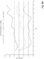
- FIG. 5A is a normalized graphical representation of the resistivity over time measured by the resistivity flow monitors of the embodiment of FIG. 2B ;
- FIG. 5B is a time-aligned version of the graphical representation of FIG. 5A , illustrating the similarity of the temporal resistivity measurements of the various RFM units;
- FIG. 5C is a graphical representation of the resistivity data measured by the resistivity flow monitors of the embodiment of FIG. 4A cross-correlated with each other;
- FIG. 6A represents tabulated resistivity data acquired by the system of FIG. 2B ;
- FIG. 6B is a graphical representation of the flow rate of fluid through the various injector zones compared to the total flow rate
- FIG. 6C is a graphical representation of the percentage of the total flow through the various injector zones
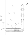
- FIG. 7 is a schematic representation of another embodiment of the fluid flow monitoring system disclosed herein, wherein fluid is injected via the annulus of a wellbore and a “slug” of salt water is injected between injections of clean water;
- FIG. 8A is a schematic representation of a flow monitoring system in combination with a flow control system having control sleeves in a fully closed position implemented in an injector well;
- FIG. 8B is a schematic representation of the flow monitoring and control system of FIG. 8A wherein the control sleeves are in the fully open position;
- FIG. 11A is a side view of an isolation packer having a wireline installed along an outside of the tubing string therethrough (shown in dotted lines);
- FIG. 11B is a side view of a wireline running along a tubing string and in communication with the resistivity flow monitors and control valves on a sub.
- a system and method are provided herein for acquiring data regarding fluid flow through various injection zones 4 of an injector well 2 in a fluid flood secondary hydrocarbon recovery operation and, in some embodiments, for adjusting the fluid flow through one or more of the injection zones 4 .
- references to “fluid” herein include both liquid and gas, such as water and CO 2 .
- references to a wellbore “tubing string” herein include, but are not limited to, coiled tubing, jointed tubing, and the like.
- At least two injection fluids 20 can be injected into the injector well 2 in an alternating manner and at a known injection rate.
- the first injection fluid 20 a possesses a first value of the measurable property
- the second injection fluid 20 b has a second value of the measurable property that is different from the first value.
- the first fluid 20 a can be saline water having a low electrical resistivity
- the second fluid 20 b can be clean water having a relatively higher resistivity.
- Other fluids or additives can be used to provide the first and second fluids 20 a , 20 b with their respective first and second values of the measurable property.
- a tracer can be added to the first fluid 20 a that is not added to the second fluid 20 b .
- Such use of tracers and sensors 12 configured to detect said tracers in the injector well 2 provides a more immediate indication of fluid flow behavior when compared to the conventional mixing of a tracer into the injected fluid and measuring the volume of tracer-containing fluid produced from the producer well, as the flow rates of fluid out of each injection zone 4 can be calculated using measurements obtained by the sensors 12 located in the injector well 2 as opposed to waiting for the injected fluid to reach the producer ell and be produced to surface.
- embodiments described herein relate to the context of water injection with electrical resistivity as the measurable property, and wherein the additive is salt or the absence thereof.
- the level of salt in a fluid is inversely proportional to the resistivity thereof.
- An initialization sensor 13 also configured to monitor the measurable property, can be located at an initialization location uphole of the rest of the sensors 12 and be used to record an initialization time when the first or second fluid 20 a , 20 b arrives thereat.
- the fluid flow rate at each of the sensors 12 can be calculated and compared to determine the flow rate out of the injection zones 4 located between pairs of sensors 12 .
- the difference in flow rate between two sensors 12 is the flow rate of fluid exiting the injection well 2 via the injection zones 4 therebetween.
- At least two sensors 12 can be located upstream of the injection zones 4 and spaced from one another such that the initial flow rate can be calculated.
- the initialization sensor 13 and a sensor 12 a located upstream of the first injection zone 4 a can be used to detect and log the arrival times of the fluids 20 a , 20 b , and the flow rate along the bore 16 can be calculated using the arrival times, the distance between the sensors 12 a , 13 , and the cross-sectional flow area of the flow conduit—i.e. the tubing string bore 16 or annulus 18 —between the sensors 12 , 13 a.
- the flow monitoring system 10 can be implemented together with a flow control system 60 configured to adjust the fluid flow through each of the injection zones 4 , thereby permitting the flow of fluid from the injector well 2 through the hydrocarbon formation into the producer well 6 to be tuned to provide the desired flow characteristics.
- a cased injector well 2 has a tubing string 14 extending therethrough and a substantially horizontal section.
- An initializing resistivity flow monitor (RFM) unit 13 is installed on the tubing string 14 upstream of the injection zones 4 of the injection well 2 and configured to measure resistivity of fluid flowing through the bore 16 of the tubing string 14 .
- RFM resistivity flow monitor
- a first RFM unit 12 a is installed at the toe of the tubing string 14
- a fourth RFM unit 12 d is installed at the heel of the tubing string 14 .
- Second and third RFM units 12 b , 12 bc can be installed on the tubing string 14 at intervals between the first and fourth units 12 a , 12 d as shown.
- the first, second, third, and fourth RFM units 12 a - 12 d are positioned upstream from respective first, second, third, and fourth injection zones 4 a - 4 d.
- Fluid 20 is injected into the injector well 2 through the tubing string bore 16 , exits a downhole end of the tubing string, and flows uphole through the annulus 18 , such that fluid 20 first exits the injector well 2 into the formation through a first injection zone 4 a adjacent the toe of the tubing string 14 and downstream of the first RFM unit 12 a .
- the injected fluid 20 then proceeds uphole through the annulus 18 and sequentially past the second, third, and fourth injection zones 4 b - 4 d , each injection zone downstream of its respective RFM unit 12 b - 12 d.
- the bore 16 of the tubing string 14 and the annulus 18 can each be fancifully assigned a 1 m 2 cross-sectional flow area.
- the distance from the initializing RFM unit 13 to the first RFM unit 12 a located adjacent to, and upstream of, the first injection zone 4 a is 900 m, and the distance between the first RFM unit 12 a and the subsequent second RFM unit 12 b , located adjacent to and upstream of a second injection zone 4 b , is 100 m.
- the fluid 20 is injected into the injector well 2 at 1 m 3 /s, it will take 1000 seconds for the fluid to travel from the initializing RFM 13 to the second RFM 12 b if no fluid exited the injection well 2 through the first injection zone 4 a . However, if the fluid takes longer than 1000 seconds to travel from the initializing RFM 13 to the second RFM 12 b , then it can be concluded that some fluid 20 exited into the hydrocarbon formation through the first injection zone 4 a , assuming that the first injection zone 4 a is the only available means for fluid 20 to exit the injector well 2 .
- the flow rates of the injected fluid 20 between the various RFM units 12 , 13 can be calculated using the time it takes the fluid 20 to travel from one RFM to the next, calculated as the difference between fluid arrival times, and the known volume of the fluid conduit between the RFMs, calculated from the distance between the RFMs and the cross-sectional area of the fluid conduit.
- the rate of fluid flow from the initialization RFM 13 to the first RFM 12 a can be determined with the equation:
- the rate of fluid flow from the first RFM 12 a to the second RFM 12 b can be determined using the equation:
- the rate of fluid flow to an RFM 12 n from a previous RFM 12 n ⁇ 1 can be determined using the equation:
- the flow rate of fluid flowing into the formation through the first injection zone 4 a can be calculated as Q 1 ⁇ Q 2 .
- the flow rate of fluid flowing into the formation through the second injection zone 4 b can be calculated as Q 3 ⁇ Q 2 .
- the low rate of fluid flowing into the formation through subsequent injection zones can be determined in a similar manner, where the flow rate through an injection zone located between RFMs 12 n and 12 n ⁇ 1 is Q n ⁇ Q n ⁇ 1 .
- the initializing RFM 13 can be installed at any location of the injector 2 upstream of the first injection zone 4 a . So long as the distances between the various RFMs 12 , 13 and the cross-sectional area of the fluid conduit therebetween are known, and the injection rate of fluid 20 into the injector well 2 (before the fluid reaches the first injection zone) is known, the fluid flow rate out of the injection zones 4 can be calculated in the manner described above.
- At least two RFMs 12 can be installed upstream of the first injection zone 7 a for calculating the initial flow rate Q 1 , assuming that substantially no fluid 20 has exited the injector well 2 between the two RFMs 12 .
- the initializing RFM 13 and the first RFM 12 a of FIG. 2A can be used to calculate the initial flow rate Q 1 .
- Q 1 can also be measured at the pumping system 40 . For example, for positive displacement pumps, each stroke of the pump displaces a known volume of fluid. Thus, the speed of the pump, e.g. the strokes per minute, can be multiplied with the displacement volume of the pump to obtain the flow rate.
- fluid 20 can be injected into the annulus 18 of the injector well 2 .
- fluid flow sensors 12 can be placed upstream (in this instance, uphole) of each fluid injection zone 4 to detect the arrival of the fluids 20 thereat.
- the fluids 20 When fluids 20 are injected into the injector well 2 through the annulus 18 , the fluids first exit the injector well 2 into the formation through a first injection zone 4 a adjacent the heel of the tubing string 14 and then sequentially through second, third, and fourth injection zones 4 b - 4 d , each subsequent injection zone located downstream of the previous zone.
- Fluid flow rates through the various injection zones 4 of the injection well 2 into the hydrocarbon formation can be calculated in a manner similar to the calculations above, with V 1 being the volume of the annulus extending from the initialization RFM 13 to the first RFM 12 a.
- FIG. 1 shows an embodiment of a water-flooding, secondary production operation with a flow monitoring system 10 located within an injector well 2 having a plurality of injection zones 4 through which fluid 20 injected into the injector bore may be introduced into the hydrocarbon formation for transport and displacement through the formation to the producer well 6 .
- a plurality of RFMs 12 are axially spaced along a tubing string 14 located inside of the injector well 2 , and configured to measure the resistivity of the fluid 20 flowing thereby.
- the RFMs 12 can be located on flow subs 22 (detailed in FIG. 4A ) positioned along a string of jointed tubing making up the tubing string 14 to be run into the injection well.
- the RFMs 12 ( 12 a , 12 b , 12 c . . . 12 n ) can be configured to measure the resistivity of fluid 20 flowing through the annulus 18 formed between the tubing string 14 and the injector well casing, the bore 24 of the flow sub 22 or the tubing string bore 16 , or both, depending on the type of fluid flooding operation implemented.
- the flow subs 24 are positioned at intervals along the tubing string 14 , such that at least one RFM 12 is located upstream of each injection zone 4 ( 4 a , 4 b , 4 c . . . 4 n ) when the tubing string 14 is run in hole to the desired depth and hung in an operating position.
- the initializing RFM 13 can be located on a flow sub 22 installed on the tubing string 14 upstream of the injection zones 4 .
- a flow sub 22 can also be positioned downstream of the last injection zone 4 n .
- the distances of the RFMs 12 , 13 from surface, and the distances between the various RFMs 12 , 13 are known.
- power is supplied to the RFMs 12 via a portable power-source 26 located in the flow sub 22
- the resistivity data acquired by the RFMs 12 is stored in on-board memory modules 28 also located in the flow subs 22 .
- power is supplied via an external power source 30 located at surface and connected to the flow subs 22 via a wireline 34 or other suitable means.
- the resistivity data acquired by the RFMs can be stored on an external data storage unit 32 located at surface and connected to the flow subs 22 via wireline 34 .
- the flow subs 22 can have on-board power sources 26 and memory modules 28 as a backup to the surface power source 30 and data storage unit 32 .
- a controller 36 such as a computer, can be used to calculate the fluid flow rates of the injection zones 4 using the resistivity data acquired by the RFMs 12 and stored in the surface data storage unit 32 or on-board memory modules 28 .
- the resistivity data can be transmitted to the controller in real-time or near real-time, such that the calculated flow rates out of the injection zones 4 substantially represent real-time flow rates.
- the controller 36 can be directly connected to the data storage unit 32 or an uphole end of the wireline 34 to receive resistivity data.
- the controller 36 can also be remotely connected to the flow monitoring system 10 .
- a wireless communications interface 38 at surface can be connected to the data storage unit 32 or uphole end of the wireline 34 , and configured to interface with a controller 36 via any suitable wireless communications network such as a cellular network, Bluetooth, and the like.
- the controller 36 can be any device capable of communication using the above communications networks, such as a personal computer, laptop, tablet, smartphone, and the like.
- each flow sub 22 can have multiple RFMs 12 spaced radially thereabout.
- Such a configuration is advantageous in wellbores having substantively horizontal segments, where hydrocarbons and other materials having a different viscosity than water can accumulate.
- the flow rate of fluid at an upper cross-sectional portion of the wellbore is different than the flow rate at a lower cross-sectional portion.
- the flow rates measured by the radially spaced RFMs of an injection zone can be averaged to obtain the overall flow rate.
- the arrival times of the first or second fluid 20 at the flow sub 22 can be averaged and the flow rate calculated from the averaged arrival time.
- the average arrival time can be a simple average, a weighted average, a median, or another suitable composite calculated from the measurements of the RFMs 12 of the flow sub 22 .
- Flow rate data that falls outside an expected range can be discarded as necessary.
- the calculated volume of fluid flowing in the wellbore can be adjusted. This might be the case if some of the RFMs 12 did not observe any noticeable changes in resistivity. If this is combined with orientation data of the RFMs 12 , and the RFMs 12 that did not observe any noticeable resistivity changes are located on the “bottom” of the horizontal section of the wellbore, it can be inferred that fluid flow through a portion of the cross-sectional area of the wellbore is being inhibited, for example by sand or sediment produced from formation. One could then adjust the volume of fluid moving and hence the calculated flow rate through the portion of the cross-sectional area of the wellbore experiencing inhibited flow. Since volumetric measurements of fluid are not obtained continuously along the horizontal wellbore section, but are only estimated at locations having RFMs 12 , these flow rate calculations may not be as accurate as if the wellbore was clean and there is free flow through all cross-sectional portions thereof.
- a pump system 40 at surface is configured to alternatingly pump the first and second fluids 20 a , 20 b from first and second fluid sources 42 a , 42 b , respectively, into the injector bore.
- the first fluid source 42 a contains clean water 20 a having a first resistivity level
- the second fluid source 42 b contains saline water 20 b having a second resistivity level that is lower than the first resistivity level.
- the salt content of the salt water 20 b is selected such that the resistivity thereof can be sufficiently differentiated from the resistivity of the clean water 20 a when measured by the RFMs 12 .
- the pump system 40 can comprise a generator 72 for supplying power to an electric motor 76 operatively coupled to a pressure pump 78 , such as a triplex plunger pump.
- the pump 78 is fluidly connected to the first and second fluid sources 42 a , 42 b and the tubing string bore 16 and/or annulus 18 of the injector well 2 and configured to deliver the first and second fluids 20 a , 20 b thereto.
- a variable frequency drive (VFD) 74 can be connected between the generator 72 and motor 76 for adjusting the speed of the motor 76 and pumping rate.
- Flowmeters 90 can be located along the fluid lines leading to the tubing string bore 16 and annulus 18 to measure the flow rate of the fluids 20 being delivered thereto.
- a pressure gauge 80 can be configured to measure the pressure in the fluid line, and an electrical control line 82 can connect the pressure gauge 80 and the VFD 74 .
- the VFD 74 can be configured to adjust the speed of the motor 76 and flow rate in response to the pressure readings from the pressure gauge 80 in order to maintain pressure in the fluid line within a desired pressure range.
- the pump system 40 can be configured to inject the fluids 20 a , 20 b into the injection well 2 at a substantially constant flow rate, such that the fluid injection rate does not change substantially from the time a fluid reaches the first of the RFMs 12 to the time the fluid reaches the last of the RFMs 12 .
- a stable fluid injection rate throughout the flow rate monitoring process is desirable in order to establish measures of flow rates and provide more accurate calculations of the established flow rates at the various RFMs 12 .
- the percentage of fluid lost between two adjacent RFMs 12 may still be calculated if the total volume of injected fluid 20 is known between the arrival time of the fluid at an RFM and the arrival time at a subsequent RFM.
- the total injected volume of fluid between the arrival time at the initialization RFM 13 and the arrival time at the first RFM 12 a is equal to some value measured as volume/minute, which could be compared to the volume of the flow conduit between initialization and first RFM 13 , 12 a divided by the same time interval—which would allow for the calculation of what percentage of fluid is exiting the injection bore between those two RFMs.
- the fluids 20 a , 20 b are injected downhole through the tubing string bore 16 and flow uphole towards surface through the annulus 18 , exiting to the hydrocarbon formation via the injection zones 4 , beginning with the most downhole injection zone. In other embodiments, the fluids 20 a , 20 b are injected downhole through the annulus 18 and exit to the hydrocarbon formation via the injection zones 4 , beginning with the most uphold injection zone.
- a plurality of packer subs 44 each having an isolation packer 46 are located along the tubing string 14 and are selectively deployable to isolate each of the injection zones 4 .
- a toe sub 50 having a toe valve 52 is located at a downhole end of the tubing string 14 for preventing fluid communication out of the tubing string bore 16 via said downhole end.
- the isolation packers 46 can be inflatable packers that are expandable by pressurizing the tubing string bore 16 , such as by closing the toe valve 52 and injecting fluid into the tubing string bore 16 to increase the pressure therein. Fluid communication between the tubing string bore 16 and the isolation packers 46 can be controlled by a packer valve 48 of each of the isolation packers 46 .
- the packer valves 48 can be opened to permit fluid communication between the packer elements 46 and the tubing bore 16 , such as when setting or collapsing the packer elements 46 .
- the packer valve 48 can be closed to prevent fluid communication between the packer elements 46 and the tubing string bore 16 , such as when the packer elements 46 are to be maintained in the set position.
- the tubing string 14 can have tubing string ports 54 located adjacent the locations of the injection zones 4 for permitting fluid communication between the tubing string bore 16 and the annulus 18 .
- the RFMs 12 can be configured to measure the resistivity of fluid 20 flowing inside the tubing string bore 16 and are each located upstream of respective ports 54 of the tubing string.
- the RFMs 12 can be configured to measure the resistivity of fluid 20 in the annulus to detect the arrival times of the injected fluid 20 therein.
- the packer subs 44 and toe sub 50 can be connected to the power source 30 and controller 36 at surface via the wireline 34 .
- the controller 36 can be configured to open and close the packer valves 48 as required to set and unset the packer elements 46 , and also to open and close the toe valve 52 .
- the controller 36 can also be configured to monitor the operation of the packers 46 , such as monitoring packer bladder pressure for confirming successful setting of the packer.
- isolation packers 46 are set by pressurizing the tubing string bore 16 , in other embodiments, the isolation packers 46 can be set by other means such as rotation of the tubing string 14 , or can otherwise be pressure, mechanically, or electrically activated.
- the flow monitoring system 10 can be used in a production well 6 to determine the flow rate of fluid into the production well through various fluid-receiving zones 8 , such as perforations or open ports formed in the production well casing.
- a tubing string 14 having a plurality of RFMs 12 installed therealong is run into the production well 6 such that the RFMs 12 are located adjacent to the fluid-receiving zones 8 , and fluids 20 a , 20 b are alternatingly injected into the production well 6 through the tubing string 14 .
- the rate of fluid flow into the formation through the various fluid-receiving zones 8 can be calculated using the methods disclosed above.
- this method can be used to determine the flow rate of fluid into the production well 6 through its various fluid-receiving zones 8 .
- the injection well can also comprise a flow control system 60 for adjusting the flow rate of fluids through the injection zones 4 of the injection well 2 in response to the flow information obtained from the flow monitoring system 10 .
- flow through the injection zones 4 can be adjusted to produce more uniform flow rates across the injection zones 4 , resulting in a more uniform flood front and improving production.
- the flow control system 60 comprises a plurality of flow control devices 62 installed along the tubing string 14 or the injector well casing.
- the control devices 62 can be actuated to adjust fluid communication between the tubing string bore 16 and the annulus 18 via the ports or openings 54 of the tubing string 14 .
- the control devices 62 can be actuated to adjust fluid communication between the annulus 18 and the hydrocarbon formation via the injection zones 4 .
- Each flow control device 62 is capable of actuation between a closed position, wherein the devices prevents fluid communication therethrough, and an open position, wherein the device permits fluid communication therethrough.
- One device in a zone 4 opens or shuts off flow thereto.
- a plurality of devices along a zone 4 permits finer control of the adjustment of fluid communication to the zone through selective opening and closing of such devices.
- the flow control devices 62 are actuable to various positions intermediate the open and closed positions, thereby allowing the fluid flow rate therethrough to be tuned to produce the desired fluid flow characteristics. In some embodiments, the flow control devices 62 are infinitely adjustable. In other embodiments, the flow control devices 62 are adjustable between a plurality of discrete, finite positions.
- the flow control devices 62 are electrically actuable, each device 62 being operatively connected to a respective drive mechanism 64 , such as an electric motor, configured to actuate the flow control devices 62 to their various positions.
- the drive mechanisms 64 can be connected to the power source 30 and controller 36 at surface via the wireline 34 , similarly to the flow subs 22 and packer subs 44 .
- the controller 36 receives resistivity data from the flow monitoring system 10 and calculates the fluid flow rates of the injection zones 4 .
- the controller 36 can also be configured to transmit instructions to the drive mechanisms 64 of the flow control devices 62 to adjust fluid flow through the injection zones 4 in response to the calculated fluid flow data.
- the controller 36 can be capable of adjusting the flow control devices 62 individually as well as collectively.
- the receipt of resistivity data, calculation of fluid flow rates, and the transmission of instructions to the flow control system 60 takes place in real-time or near real-time, such that the fluid flow characteristics of the injector well 2 can be monitored and adjusted quickly as fluid flow conditions change.
- the adjustments transmitted to the fluid control system 60 are selected manually. In other embodiments, the adjustments are selected and transmitted automatically.
- the RFMs 12 , isolation packers 46 , flow control devices 62 , and other components of the flow monitoring and flow control systems 10 , 60 are made of a corrosion-resistant material such as stainless steel or ceramics, as wellbore fluids, as well as the introduction of salt water, can cause significant corrosive wear on equipment within the wellbore.
- the flow monitoring system 10 comprises a plurality of RFMs 12 axially spaced along a tubing string 14 , and one initializing RFM 13 located on the tubing string 14 upstream of the other RFMs 12 .
- the RFMs 12 , 13 are configured to detect the resistivity of the fluid 20 flowing thereby in the tubing string bore 16 .
- the flow control system 60 comprises a plurality of actuable control sleeve valves 62 spaced along the tubing string 14 .
- the control sleeves 62 are each operatively connected to a respective drive mechanism 64 configured to actuate the control sleeves 62 between a fully open position, wherein sleeve flow ports 66 of the sleeves 62 are aligned with respective ports 54 of the tubing string 14 , and a fully closed position, wherein the sleeve flow ports 66 are misaligned with the tubing string ports 54 .
- the sleeves 62 are also capable of being actuated to a number of intermediate positions between the fully opened and fully closed positions.
- the RFMs 12 and control sleeves 62 can be located on common flow subs 22 while the packers 46 are located on separate packer subs 44 .
- the RFMs 12 , sleeves 62 , and isolation packers 46 can all be located on common subs, or are all located on separate subs.
- the flow subs 22 having the RFMs 12 and control sleeves 62 can be installed along the tubing string 14 such that each RFM 12 and control sleeve 62 will be located adjacent to a corresponding injection zone 4 of the injection well 2 when the tubing string 14 is run into the injector well 2 to a desired depth.
- the RFMs 12 are each located upstream of respective tubing string ports 54 of the tubing string 14 .
- the packer subs 44 are installed along the tubing string 14 such that each injection zone 4 is straddled by at least two packers 46 .
- a wireline 34 is connected to a power supply 30 and controller 36 at a surface end and to the flow subs 22 and packer subs 44 along the length of the wireline 34 to provide power to the components and permit data transfer between the controller and the RFMs 12 , packer valves 48 , and sleeve drive mechanisms 64 .
- the controller 36 receives and processes resistivity data from the RFMs 12 and transmits instructions to the control sleeve drive mechanisms 64 to adjust flow through the injection zones 4 accordingly.
- the wireline 34 can be secured to the tubing string 14 , such as with a plurality of straps or clamps.
- the toe valve 52 is first activated to seal the downhole end of the tubing string 14 .
- the isolation packer valves 48 can then be opened, and the control sleeves 62 actuated to the fully closed position. Fluid 20 a , 20 b can then be injected into the tubing string bore 16 to pressurize the bore 16 and inflate the isolation packers 46 , thereby fluidly isolating the injection zones 4 .
- the packer valves 48 can be closed to maintain the packers 46 in the set position.
- the control sleeves 62 can then be actuated to the desired starting position, for example the fully open position, and the first and second fluids 20 a , 20 b , in this case clean and salt water, are alternatingly injected into the tubing string bore 16 .
- the injected fluid 20 a , 20 b flows from the bore 16 of the tubing string into the annulus 18 via the tubing string ports 54 , and from the annulus 18 into the hydrocarbon formation through the openings of the corresponding injection zone 4 .
- the RFMs 12 detect and log the arrival times of the injected fluids 20 a , 20 b , which can be used to calculate the fluid flow rates through the various injection zones 4 , as described above.
- the control sleeves 62 can be adjusted in real-time or near real-time by the controller 36 in response to the calculated fluid flow rates in order to produce a more uniform flood front.
- a controller or computer 36 is used to receive and process resistivity data from the RFMs 12 to calculate the percentage flow rate of fluid flowing out to the formation through each injection zone 4 .
- the computer 36 also displays the position of the control sleeves 30 corresponding to each injection zone 4 .
- An operator can use the computer 36 to manually change the position of the control sleeves 62 in response to the calculated flow rates, or a computer program can be used to automatically adjust the position of the sleeves 62 .
- the packer valves 48 of the isolation packers 46 can be opened to release pressure from and unset the packers.
- the tubing string 14 can then be retrieved from the injector well 2 and the equipment removed therefrom to be used in a new wellbore.
- initial flow tests to determine the flow characteristics of the injection zones 4 can be run by alternatingly injecting clean water 20 a and salt water 20 b into injector well 2 through the tubing string bore 16 and back uphole through the annulus 18 , or downhole through the annulus 18 .
- the toe valve 52 is open, the isolation packers 46 are not set, and the control sleeves 62 are closed.
- the isolation packers 46 can be set and the fluid flow monitoring and flow control process can be carried out as described above.
- a power supply 30 can be located at surface and connected to the RFMs 12 , control sleeve drive mechanisms 64 , and packer valves 48 via wireline 34 .
- a data storage unit 32 can also be located at surface and connected to the wireline 34 to receive resistivity data from the RFMs 12 .
- the data storage unit 32 can be integral with, or separate from, the controller 36 .
- a portable power source 26 such as a battery, is located in the RFM 12 , control sleeve 62 , and/or isolation packer 46 subs to power said components either alone or in combination with another power source.
- an on-board memory module 28 can also be located in the subs for storing the acquired resistivity data, either as a backup to the data sent to the data storage unit at surface, or as stand-alone data storage. Flow data stored on the memory modules 28 of the RFM subs 22 can be analyzed when the tubing string 14 is retrieved from the injector well 2 .
- the wireline 34 can terminate on a first side of the flow and packer subs 22 , 44 at a first connection thereof.
- An electrical conduit can extend through the subs 22 , 44 from the first connection to a second connection located at a second side of the sub opposite the first side. In this manner, the subs 22 , 44 can be electrically connected to each other via discrete sections of wireline 34 .
- a single continuous length of wireline 34 can be run along the tubing string 14 to electrically connect all of the subs 22 , 44 .
- Use of a single continuous wireline 34 is desirable, as such a configuration makes assembly of the tubing string 14 and electrical connection of the subs 22 , 44 more convenient.
- the continuous length of wireline 34 can be secured to the tubing string 14 with axially spaced clamps, straps, or other suitable securing means.
- Pins or similar devices 35 can be used to pierce the wireline 34 to establish electrical connectivity between the wireline and the subs 22 , 44 or other tubing string components without severing the wireline 34 .
- a track or race 45 can be formed in the packer subs 44 to permit the wireline 34 to run therethrough.
- Said track 45 can have seals for engaging with the wireline 34 to prevent fluid from bypassing the packer elements 46 when they are deployed.
- FIGS. 2B and 2C depict a test of the flow monitoring system 10 described above, RFM subs 22 were installed along a tubing string 14 comprising jointed tubing, which was run into an injector well 2 , forming an annulus 18 between the tubing string 14 and the injector well 2 .
- the RFMs 12 of the RFM subs 22 were configured to measure the resistivity of fluid flowing thereby in the annulus 18 .
- Power was supplied to the RFMs 12 via an on-board power-source 26 in the RFM subs 22 , and the resistivity data acquired by the RFMs 12 were stored in an on-board memory module 28 .
- RFM 13 An initializing RFM 13 was positioned at the wellhead, and RFM subs 22 having first, second, third, and fourth RFMs 12 a - 12 d were installed along the tubing string 14 at depths of 1253 m, 1134 m, 997 m, and 831 m, respectively, such that the RFMs 12 were located adjacent to, and upstream of, respective first, second, third, and fourth injection zones 4 a - 4 d .
- the annulus 18 was sealed at surface, and clean water 20 a and salt water 20 b were alternatingly injected into the tubing string bore 16 over the course of 18 days at a substantially constant rate, and the resistivity of the injected fluids 20 a , 20 b were measured by the RFMs 12 to detect and log the arrival times of the clean and salt water at each RFM 12 .
- FIG. 5A is a normalized graph of the resistivity measured by each RFM over 18 days, showing significant increases and drops in resistivity corresponding with the arrival of clean water 20 a and salt water 20 b at the RFMs 12 .
- the resistivity measured by the RFMs 12 further downhole can be less than that measured by RFMs 12 closer to surface due to the contamination of the electrodes thereof by hydrocarbons and other substances in the wellbore. Therefore, the injected clean and salt water 20 a , 20 b should be selected to have sufficiently distinguishable resistivities even when measured by contaminated or corroded RFMs 12 .
- FIG. 5B shows the normalized resistivity data after being time-aligned, which better illustrates that the fluid interface between clean water 20 a and salt water 20 b can be easily identified and is relatively consistent across all of the RFMs 12 .
- the resistivity data for the RFMs 12 can also be cross-correlated in order to facilitate determination of the time clean water 20 a or salt water 20 b arrives at a RFM unit 12 .
- resistivity data of the initializing RFM 13 was cross-correlated with the data from the first, second, and third RFMs 12 a - 12 c .
- the peaks of the cross-correlation graph indicate the time at which maximum similarity occurs between the collected data. The timing of the peaks can be used to more easily determine the arrival times of the injected fluid at the RFMs 12 .
- the arrival times of the injected fluid 20 a , 20 b can be determined either by visual inspection or review of the cross-correlated data, or automatically, for example by using an algorithm that identifies the times at which the maxima of the cross-correlated functions occur.
- FIG. 6A is a table showing the arrival times of the clean water 20 a and salt water 20 b travelling from the initializing RFM 13 to RFM unit 12 a , and from RFM units 12 a to 12 b , 12 b to 12 c , and 12 c to 12 d .
- the fluid flow rates from the initializing RFM 13 to the other RFM units 12 were calculated based on the fluid arrival times, and the percentage loss of fluid flow rate between RFM stages was also calculated to determine what percentage of the total injected fluid flow rate exited the injector bore through the various injection zones.
- FIG. 6B graphically represents the absolute flow rate of injected fluid into the wellbore and into the formation through the injection zones 4
- FIG. 6C graphically represents the percentage of the total flow rate of fluid travelling through each injection zone 4 into the formation.
- a power source 30 with an electrical interface is connected to power the tubing string components and ensure each added tubing string component is functioning properly. Testing the tubing string components as they are installed avoids assembling the entire tubing string 14 only to find a component is malfunctioning, requiring the entire tubing string to be pulled out of the wellbore.
- the tubing string 14 can be hung in position and the wireline 34 isolated.
- the power source 30 and controller 36 /wireless communications interface 38 can be connected to the wireline 34 .
- the controller 36 can run a diagnostic routine to verify that all tubing string components are functioning properly.
- the pump system 40 and fluid sources 42 a , 42 b can be connected to the wellhead for injecting the first and second fluids 20 a , 20 b into the injector well 2 .
- the fluids 20 a , 20 b can then be alternatingly injected into the injector well 2 to determine the flow characteristics thereof and how much of the fluid flow is exiting the injection zones 4 of the well.
- the first and second fluids 20 a , 20 b can again be alternatingly pumped into the injector well 2 and the flow rates through the injection zones 4 can be calculated to determine where the flow is going.
- Such flow monitoring can take place at certain time intervals, for example weekly, to ensure that the fluid flow is substantially even for all injection zones 4 , and the flow control devices 62 can be adjusted.
- fluid can be injected down the annulus 18 if the isolation packers are not set.
Abstract
Description
-
- where Q1 is the rate of fluid flow from the
initialization RFM 13 to thefirst RFM 12 a; - V1 is the volume of the tubing extending from the
initialization RFM 13 to thefirst RFM 12 a; - t0 is the time at which the injected fluid reaches the
initialization RFM 13; and - t1 is the time at which the injected fluid reaches the
first RFM 12 a;
- where Q1 is the rate of fluid flow from the
-
- where V2 is the volume of the annulus extending from the
first RFM 12 a to thesecond RFM 12 b located adjacent to, and downstream from, thefirst injection zone 4 a; and - t2 is the time at which the injected fluid reaches the
second RFM 12 b.
- where V2 is the volume of the annulus extending from the
-
- where Vn is the volume of the annulus extending from the previous RFM 12 n−1 to the RFM 12 n;
- tn is the arrival time of the injected fluid at the RFM 12 n; and
- tn−1 is the arrival time of the injected fluid at the previous RFM 12 n−1
Claims (19)
Priority Applications (1)
| Application Number | Priority Date | Filing Date | Title |
|---|---|---|---|
| US16/735,552 US11215048B2 (en) | 2019-01-04 | 2020-01-06 | System and method for monitoring and controlling fluid flow |
Applications Claiming Priority (2)
| Application Number | Priority Date | Filing Date | Title |
|---|---|---|---|
| US201962788289P | 2019-01-04 | 2019-01-04 | |
| US16/735,552 US11215048B2 (en) | 2019-01-04 | 2020-01-06 | System and method for monitoring and controlling fluid flow |
Publications (2)
| Publication Number | Publication Date |
|---|---|
| US20200217189A1 US20200217189A1 (en) | 2020-07-09 |
| US11215048B2 true US11215048B2 (en) | 2022-01-04 |
Family
ID=71403472
Family Applications (1)
| Application Number | Title | Priority Date | Filing Date |
|---|---|---|---|
| US16/735,552 Active 2040-02-28 US11215048B2 (en) | 2019-01-04 | 2020-01-06 | System and method for monitoring and controlling fluid flow |
Country Status (2)
| Country | Link |
|---|---|
| US (1) | US11215048B2 (en) |
| CA (1) | CA3066565A1 (en) |
Families Citing this family (4)
| Publication number | Priority date | Publication date | Assignee | Title |
|---|---|---|---|---|
| CA3085002A1 (en) * | 2017-12-13 | 2019-06-20 | Source Rock Energy Partners Inc. | Inflow testing systems and methods for oil and/or gas wells |
| US11261715B2 (en) * | 2019-09-27 | 2022-03-01 | Ncs Multistage Inc. | In situ injection or production via a well using selective operation of multi-valve assemblies with choked configurations |
| US11585206B2 (en) | 2021-03-09 | 2023-02-21 | Saudi Arabian Oil Company | Injection of additives into a produced hydrocarbon line |
| CN115387764B (en) * | 2022-09-13 | 2024-01-05 | 西安洛科电子科技股份有限公司 | Manual-automatic adjusting separate injection instrument and water injection method |
Citations (6)
| Publication number | Priority date | Publication date | Assignee | Title |
|---|---|---|---|---|
| US4482806A (en) * | 1981-10-26 | 1984-11-13 | The Standard Oil Company | Multi-tracer logging technique |
| US5044436A (en) * | 1990-08-24 | 1991-09-03 | Chevron Research And Technology Company | Steam injection profiling with unstable radioactive isotopes |
| US6840316B2 (en) * | 2000-01-24 | 2005-01-11 | Shell Oil Company | Tracker injection in a production well |
| US20150134253A1 (en) * | 2012-04-16 | 2015-05-14 | Weatherford/Lamb, Inc. | Method and apparatus for monitoring a downhole tool |
| US20160047232A1 (en) * | 2014-08-15 | 2016-02-18 | Baker Hughes Incorporated | Methods and systems for monitoring a subterranean formation and wellbore production |
| US20200123896A1 (en) * | 2018-10-18 | 2020-04-23 | Reservoir Metrics Ip Holdings, Llc | Method to determine tracer response from non-ideal chemical tracers |
-
2020
- 2020-01-06 US US16/735,552 patent/US11215048B2/en active Active
- 2020-01-06 CA CA3066565A patent/CA3066565A1/en active Pending
Patent Citations (6)
| Publication number | Priority date | Publication date | Assignee | Title |
|---|---|---|---|---|
| US4482806A (en) * | 1981-10-26 | 1984-11-13 | The Standard Oil Company | Multi-tracer logging technique |
| US5044436A (en) * | 1990-08-24 | 1991-09-03 | Chevron Research And Technology Company | Steam injection profiling with unstable radioactive isotopes |
| US6840316B2 (en) * | 2000-01-24 | 2005-01-11 | Shell Oil Company | Tracker injection in a production well |
| US20150134253A1 (en) * | 2012-04-16 | 2015-05-14 | Weatherford/Lamb, Inc. | Method and apparatus for monitoring a downhole tool |
| US20160047232A1 (en) * | 2014-08-15 | 2016-02-18 | Baker Hughes Incorporated | Methods and systems for monitoring a subterranean formation and wellbore production |
| US20200123896A1 (en) * | 2018-10-18 | 2020-04-23 | Reservoir Metrics Ip Holdings, Llc | Method to determine tracer response from non-ideal chemical tracers |
Also Published As
| Publication number | Publication date |
|---|---|
| US20200217189A1 (en) | 2020-07-09 |
| CA3066565A1 (en) | 2020-07-04 |
Similar Documents
| Publication | Publication Date | Title |
|---|---|---|
| US11215048B2 (en) | System and method for monitoring and controlling fluid flow | |
| US11634977B2 (en) | Well injection and production method and system | |
| US9581017B2 (en) | Zonal testing with the use of coiled tubing | |
| US8899349B2 (en) | Methods for determining formation strength of a wellbore | |
| AU2008242750B2 (en) | System and method for water breakthrough detection and intervention in a production well | |
| AU764830B2 (en) | System and method for monitoring corrosion in oilfield wells and pipelines utilizing time-domain-reflectometry | |
| US10443379B2 (en) | Apparatus and method for testing an oil and/or gas well with a multiple-stage completion | |
| US9708906B2 (en) | Method and system for hydraulic fracture diagnosis with the use of a coiled tubing dual isolation service tool | |
| CA2855328A1 (en) | Improved re-fracturing bottom hole assembly and method | |
| RU2531414C1 (en) | Method of borehole and wellhead equipment layout for well survey envisaging injection of injection fluid to formation and extraction of fluids from formation | |
| White et al. | One Stage Forward or Two Stages Back: What Are We Treating? Identification of Internal Casing Erosion during Hydraulic Fracturing—A Montney Case Study Using Ultrasonic and Fiber-Optic Diagnostics | |
| US20160273347A1 (en) | Method for conducting well testing operations with nitrogen lifting, production logging, and buildup testing on single coiled tubing run | |
| AU2015318192B2 (en) | Method and system for hydraulic fracture diagnosis with the use of a coiled tubing dual isolation service tool | |
| Cramer et al. | Pressure-based diagnostics for evaluating treatment confinement | |
| US9970289B2 (en) | Methods and systems for assessing productivity of a beam pumped hydrocarbon producing well | |
| RU2569390C1 (en) | Borehole unit with field exploitation monitoring and control system | |
| RU2527960C1 (en) | Well surveying method | |
| Xian et al. | A new method of BHP measurement in ESP deadhead test | |
| Ruiz et al. | Well Testing Improvement Using Nitrogen Lifting in Shushufindi Field: Accelerating Well Response and Transient Data Quality | |
| US20160160638A1 (en) | Sandface liner with power, control and communication link via a tie back string |
Legal Events
| Date | Code | Title | Description |
|---|---|---|---|
| FEPP | Fee payment procedure |
Free format text: ENTITY STATUS SET TO UNDISCOUNTED (ORIGINAL EVENT CODE: BIG.); ENTITY STATUS OF PATENT OWNER: SMALL ENTITY |
|
| FEPP | Fee payment procedure |
Free format text: ENTITY STATUS SET TO SMALL (ORIGINAL EVENT CODE: SMAL); ENTITY STATUS OF PATENT OWNER: SMALL ENTITY |
|
| STPP | Information on status: patent application and granting procedure in general |
Free format text: DOCKETED NEW CASE - READY FOR EXAMINATION |
|
| AS | Assignment |
Owner name: KOBOLD CORPORATION, CANADA Free format text: ASSIGNMENT OF ASSIGNORS INTEREST;ASSIGNORS:PETRELLA, ALLAN;BROWN, MATTHEW;ANGMAN, PER;AND OTHERS;SIGNING DATES FROM 20210205 TO 20210209;REEL/FRAME:055213/0005 |
|
| STPP | Information on status: patent application and granting procedure in general |
Free format text: NON FINAL ACTION MAILED |
|
| STPP | Information on status: patent application and granting procedure in general |
Free format text: RESPONSE TO NON-FINAL OFFICE ACTION ENTERED AND FORWARDED TO EXAMINER |
|
| STPP | Information on status: patent application and granting procedure in general |
Free format text: NOTICE OF ALLOWANCE MAILED -- APPLICATION RECEIVED IN OFFICE OF PUBLICATIONS |
|
| STPP | Information on status: patent application and granting procedure in general |
Free format text: PUBLICATIONS -- ISSUE FEE PAYMENT RECEIVED |
|
| STPP | Information on status: patent application and granting procedure in general |
Free format text: PUBLICATIONS -- ISSUE FEE PAYMENT VERIFIED |
|
| STCF | Information on status: patent grant |
Free format text: PATENTED CASE |