US11214912B2 - Automatic detergent supply device and washing machine having the same - Google Patents
Automatic detergent supply device and washing machine having the same Download PDFInfo
- Publication number
- US11214912B2 US11214912B2 US16/537,903 US201916537903A US11214912B2 US 11214912 B2 US11214912 B2 US 11214912B2 US 201916537903 A US201916537903 A US 201916537903A US 11214912 B2 US11214912 B2 US 11214912B2
- Authority
- US
- United States
- Prior art keywords
- detergent
- case
- outlet
- guide member
- washing machine
- Prior art date
- Legal status (The legal status is an assumption and is not a legal conclusion. Google has not performed a legal analysis and makes no representation as to the accuracy of the status listed.)
- Active, expires
Links
Images


Classifications
-
- D—TEXTILES; PAPER
- D06—TREATMENT OF TEXTILES OR THE LIKE; LAUNDERING; FLEXIBLE MATERIALS NOT OTHERWISE PROVIDED FOR
- D06F—LAUNDERING, DRYING, IRONING, PRESSING OR FOLDING TEXTILE ARTICLES
- D06F39/00—Details of washing machines not specific to a single type of machines covered by groups D06F9/00 - D06F27/00
- D06F39/02—Devices for adding soap or other washing agents
- D06F39/022—Devices for adding soap or other washing agents in a liquid state
-
- D—TEXTILES; PAPER
- D06—TREATMENT OF TEXTILES OR THE LIKE; LAUNDERING; FLEXIBLE MATERIALS NOT OTHERWISE PROVIDED FOR
- D06F—LAUNDERING, DRYING, IRONING, PRESSING OR FOLDING TEXTILE ARTICLES
- D06F33/00—Control of operations performed in washing machines or washer-dryers
- D06F33/30—Control of washing machines characterised by the purpose or target of the control
- D06F33/32—Control of operational steps, e.g. optimisation or improvement of operational steps depending on the condition of the laundry
- D06F33/37—Control of operational steps, e.g. optimisation or improvement of operational steps depending on the condition of the laundry of metering of detergents or additives
-
- D—TEXTILES; PAPER
- D06—TREATMENT OF TEXTILES OR THE LIKE; LAUNDERING; FLEXIBLE MATERIALS NOT OTHERWISE PROVIDED FOR
- D06F—LAUNDERING, DRYING, IRONING, PRESSING OR FOLDING TEXTILE ARTICLES
- D06F39/00—Details of washing machines not specific to a single type of machines covered by groups D06F9/00 - D06F27/00
- D06F39/08—Liquid supply or discharge arrangements
- D06F39/083—Liquid discharge or recirculation arrangements
- D06F39/085—Arrangements or adaptations of pumps
-
- D—TEXTILES; PAPER
- D06—TREATMENT OF TEXTILES OR THE LIKE; LAUNDERING; FLEXIBLE MATERIALS NOT OTHERWISE PROVIDED FOR
- D06F—LAUNDERING, DRYING, IRONING, PRESSING OR FOLDING TEXTILE ARTICLES
- D06F39/00—Details of washing machines not specific to a single type of machines covered by groups D06F9/00 - D06F27/00
- D06F39/12—Casings; Tubs
-
- D—TEXTILES; PAPER
- D06—TREATMENT OF TEXTILES OR THE LIKE; LAUNDERING; FLEXIBLE MATERIALS NOT OTHERWISE PROVIDED FOR
- D06F—LAUNDERING, DRYING, IRONING, PRESSING OR FOLDING TEXTILE ARTICLES
- D06F2105/00—Systems or parameters controlled or affected by the control systems of washing machines, washer-dryers or laundry dryers
- D06F2105/42—Detergent or additive supply
Definitions
- the disclosure relates to a detergent supply device with improved detergent supply efficiency and a washing machine including the same.
- a washing machine is an apparatus that uses water and a detergent to remove contamination on laundry.
- the washing machine may rotate a washing tub using a driving force of a motor, and may proceed a series of processes such as washing, rinsing, dehydrating, or the like.
- the washing machine may include a water supply device for supplying water.
- the water supply device is connected to an external water source and may supply washing water to the washing tub.
- the washing machine may include a detergent supply device that supplies detergent.
- the washing water flowing by the water supply device is mixed with the detergent stored in a detergent case while passing through the detergent supply device and then may be supplied to the washing tub by a detergent pump.
- the stored detergent may be discharged by the detergent pump along with air introduced into the detergent case.
- the flow rate of the detergent discharged by the air discharged together is not maintained.
- Embodiments of the disclosure address the above disadvantages and other disadvantages not described above. Also, the disclosure is not required to overcome the disadvantages described above, and an embodiment may not overcome any of the problems described above.
- a detergent supply device capable of maintaining a flow rate of a detergent supplied by a detergent pump constant even if the level of the detergent remaining in a detergent case falls below to a position of a detergent outlet and a washing machine including the same.
- a detergent supply device and a washing machine including the same, capable of improving the reliability of a product by uniformly supplying the detergent stored in the detergent case to the flow path of the detergent housing.
- a washing machine includes a main body; a washing tub which is rotatable and disposed inside the main body to accommodate laundry; and a detergent supply device configured to supply a detergent to the washing tub.
- the detergent supply device includes a detergent housing disposed inside the main body and formed with a flow path through which the detergent is suppliable to the washing tub; a detergent case to be disposed inside the detergent housing, store the detergent inside therein, and formed with a detergent outlet through which the detergent stored inside the detergent case is discharged; and a detergent pump to be connected to the detergent outlet to supply the detergent stored in the detergent case to the flow path, and the detergent case includes a guide member and the detergent outlet of the detergent case is coupleable to the guide member which covers a part of an upper portion of the detergent outlet while coupled to the detergent outlet.
- the guide member may include a tunnel in a tubular shape having a bottom that is open, and a cover formed to be perpendicular to an end of the tunnel.
- the cover may be formed in a semi-circular shape having a bottom that is open.
- the tunnel may be formed to protrude toward an inside of the detergent case.
- the tunnel and the cover of the guide member are disposed inside the detergent case.
- the detergent supply device may further include a valve coupled to the detergent outlet of the detergent case to open and close the detergent outlet of the detergent case according to an operation of the detergent pump.
- the valve may be configured to move backwards and forwards inside the tunnel.
- the detergent case may be formed with a detergent inlet in an upper portion to enable the detergent to be introduced into the detergent case, and the detergent inlet in a dented shape with a predetermined depth.
- the detergent case may be attachable to and detachable from the detergent housing.
- the detergent pump may be disposed in the rear of the detergent case, and the detergent outlet is formed along a rear side of the detergent case.
- the detergent housing may be formed with a supply port that is open at a lower portion so as to supply detergent discharged from the detergent case by the detergent pump to the washing tub.
- a flow path of the detergent housing may be formed such that a lower surface is inclined toward the supply port to supply the detergent discharged to the washing tub.
- a detergent supply device to supply a detergent to a washing machine includes a detergent housing formed with a flow path for supplying a detergent to a washing tub, a detergent case to be disposed in the detergent housing, store a detergent inside therein, including a detergent outlet through which the detergent stored inside the detergent case is discharged, and a guide member which covers a part of an upper portion of the detergent outlet so as to discharge the detergent stored in the detergent case through to a lower portion of the detergent outlet, and a detergent pump connectable to the detergent outlet, to discharge the detergent stored in the detergent case to the flow path.
- the guide member may include a tunnel in a tubular shape having a bottom that is open, and a cover that is perpendicular to one end of the tunnel and formed in a semi-circular shape with a bottom that is open.
- the tunnel and the cover are disposed inside the detergent case.
- FIG. 1 is a perspective view illustrating an outer shape of a washing machine according to an embodiment
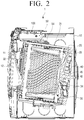
- FIG. 2 is a cross-sectional view of a washing machine according to an embodiment:
- FIG. 3 is an exploded perspective view illustrating a detergent supply device according to an embodiment
- FIG. 4 is a perspective view illustrating the inside of a detergent case according to an embodiment:
- FIG. 5 is an exploded perspective view illustrating V of FIG. 4 :
- FIGS. 6A, 6B, and 6C are views illustrating a guide member according to various embodiments
- FIG. 7 is a cross-sectional view illustrating along VII-VII line of FIG. 4 .
- FIG. 1 is a perspective view illustrating an outer shape of a washing machine according to an embodiment
- FIG. 2 is a cross-sectional view of a washing machine according to an embodiment.
- a washing machine 1 includes a main body 10 which forms an outer appearance and supports various components therein, a washing tub 20 disposed inside the main body 10 , a rotating tub 30 rotatably disposed inside the washing tub 20 , and a motor 40 for driving the rotating tub 30 .
- An inlet 11 is formed on a front side so as to input laundry to the inside of the rotating tub 30 .
- the inlet 1 is opened and closed by a door 12 installed on the front side of the main body 10 .
- a water supply pipe 50 for supplying washing water to the washing tub 20 is installed on an upper portion of the washing tub 20 .
- One side of the water supply pipe 50 is connected to a water supply device (not shown) for supplying washing water from an external water supply source, and the other side of the water supply pipe 50 is connected to the detergent supply device 100 .
- the detergent supply device 100 is connected to the washing tub 20 through a connection pipe 54 and may supply a detergent to the washing tub 20 .
- the detergent supply device 100 may include a detergent case 130 for storing a detergent, a preliminary detergent, a fabric softener, a bleach, or the like.
- the water supplied through the water supply pipe 50 may be supplied to the inside of the washing tub 20 through the detergent case 130 together with a detergent, a preliminary detergent, a fabric softener or a bleach, or the like.
- the detergent supply device 100 may be inserted into a mounting hole 15 provided in the main body and coupled.
- a drainage pump (not shown) for draining water inside the washing tub 20 to the outside of the main body 10 and a drainpipe (not shown) may be installed.
- the rotating tub 30 may include a cylindrical portion 31 , a front plate disposed in front of the cylindrical portion 31 , and a rear plate disposed in the rear side of the cylindrical portion 31 .
- the front plate may have an input port 32 for inputting the laundry, and a driving shaft 42 for transmitting the power of a motor 40 may be connected to the rear plate.
- a plurality of through holes 34 for circulating the washing water are formed around the rotating tub 30 and in an inner peripheral surface of the rotating tub 30 , a plurality of lifters 35 may be installed so that the laundry may move upward and downward when the rotating tub 30 rotates.
- a driving shaft 42 is disposed between the rotating tub 30 and the motor 40 .
- One end of the driving shaft 42 may be connected to the rear plate of the rotating tub 30 , and the other end of the driving shaft 42 may be extended to the outside of a real wall of the washing tub 20 .
- the motor 40 drives the driving shaft 42
- the rotating tub 30 connected to the driving shaft 42 may rotate around the driving shaft 42 .
- a bearing housing 45 may be installed on the rear wall of the washing tub 20 to rotatably support the driving shaft 42 . Between the bearing housing 45 and the driving shaft 42 , bearings may be installed to allow the driving shaft 42 to rotate smoothly.
- FIG. 3 is an exploded perspective view illustrating a detergent supply device according to an embodiment.
- the detergent supply device 100 may be disposed on the main body 10 .
- the detergent supply device 100 may be provided on one side of the upper portion of the main body 10 .
- the detergent supply device 100 may include a detergent housing 110 , the detergent case 130 coupled to the detergent housing 110 , a detergent pump 150 for pumping stored detergent, a discharge plate 160 , and a cover frame 170 for sealing the upper portion of the discharge plate 160 .
- an opening 118 may be formed, and the detergent case 130 may be inserted into the opening 118 of the detergent housing 110 .
- the detergent case 130 may be detachably coupled to the detergent housing 110 .
- the detergent case 130 may be provided to slidably withdraw from the detergent housing 110 .
- rails may be provided on both inner sides of the detergent housing 110 so that the detergent case 130 may slidably move while being supported by the rails.
- the detergent case 130 is detachably coupled to the detergent housing 110 , but the embodiment is not limited thereto, and the detergent case 130 may be disposed inside of the main body 10 , while being fixed to the detergent housing 110 .
- the detergent housing 110 may be of a cylindrical shape having an internal space. Accordingly, the detergent housing 110 may include the detergent case 130 inside the detergent case 130 , and a flow path 111 may be formed to serve as a passage through which the detergent and water supplied to the washing tub 20 are discharged.
- the flow path 111 formed in the detergent housing 110 may supply detergent to the washing tub 20 .
- water flown in through the cover frame 170 and the detergent, or the like, supplied from the detergent case 130 may be supplied to the washing tub 20 through a supply port 119 formed in the detergent housing 110 .
- the flow path 111 may be formed as a space which is formed by the detergent housing 110 and the cover frame 170 , by coupling the cover frame 170 at an upper portion of the detergent housing 110 .
- a water supply port 171 is formed in the cover frame 170 to allow water to flow in and a separate water supply pipe 50 (see FIG. 1 ) is connected to the water supply port 171 , so that flow in of water to the flow path 111 is available.
- the detergent housing 110 may further include a discharge plate 160 in which a plurality of through holes 161 are formed therein to uniformly discharge water flown in through the water supply port 171 at the upper portion of the flow path 111 .
- the discharge plate 160 may be provided to form a space at a lower portion of the cover frame 170 , and the discharge plate 160 may be provided in the cover frame 170 fixedly or separably.
- a supply port 119 is formed at a lower portion of the detergent housing 110 so that detergent (fabric softener, bleach, or the like) mixed with water may be supplied to the outside of the detergent supply device.
- the supply port 119 may be connected to a connection pipe 54 , and the detergent, which is mixed with water discharged through the supply port 119 may pass through the connection pipe 54 and may be supplied to the inside of the washing tub 20 .
- a lower surface of the detergent housing 110 may be inclined toward the supply port 119 so that the detergent mixed with water is not piled at the bottom of the detergent housing 110 and may be naturally discharged through the supply port 119 .
- the detergent case 130 may store a main detergent (powder detergent or liquid detergent), preliminary detergent, a fabric softener, and a bleach.
- the detergent case 130 may be divided into a first detergent case 131 a positioned on the left side to store the main detergent, and a second detergent case 131 b positioned on the right side to store the preliminary detergent, a fabric softener, a bleach, and the like.
- a detergent inlet 132 a through which detergent is input may be formed, and a door 133 a to be opened and closed may be provided in the detergent inlet 132 a .
- a detergent inlet 132 b through which the preliminary detergent, fabric softener, bleach, or the like, is input may be formed, and the door 133 b which may be opened and closed may be provided on the detergent inlet 132 b.
- the detergent case 130 may be formed in a downward direction of the detergent inlet in a dented shape with a predetermined depth, to store detergent, or the like, therein.
- a detergent outlet 134 a , 134 b formed to discharge detergent may be formed.
- the detergent outlet 134 a for discharging the stored detergent may be formed, and in the second detergent case 131 b , the detergent outlet 134 b for discharging the stored preliminary detergent, the fabric softener or the bleach, etc. may be formed.
- the detergent outlet 134 a , 134 b may be formed in a horizontal direction of the detergent case 130 .
- the horizontal direction of the detergent case 130 may mean a direction that is horizontal to a level of detergent stored inside the detergent case 130 .
- the detergent outlet 134 a , 134 b may be formed to be horizontal to a lower surface of the detergent case 130 , and may be formed at a bottom of the detergent case 130 .
- the detergent outlet 134 a , 134 b may be formed at a side surface except a lower surface and an upper surface of the detergent case 130 .
- the detergent outlets 134 a and 134 b may be formed on a rear side of the detergent case 130 , and may be connected to the detergent pump 150 disposed at the rear of the detergent case 130 to be described later for discharging the detergent stored in the detergent case 130 .
- the detergent outlets 134 a and 134 b may be connected to the detergent pump 150 in a horizontal direction.
- a guide member 120 for guiding the detergent to be discharged to the lower portion of the detergent outlets 134 a and 134 b may be coupled.
- the structure of the guide member 120 will be described later with reference to FIGS. 4 to 6 .
- a gripping portion 138 may be provided in the front side of the detergent case 130 so that a user may take out the detergent case 130 from the detergent housing 110 or put the detergent case 130 in the detergent housing 110 .
- the detergent pump 150 may be electrically connected to a processor (not shown) provided in the main body 10 of the washing machine for operating.
- the detergent pump 150 may be located at a space separated from the flow path 111 of the detergent housing 110 through which water and detergent flows in and out and the detergent case 130 .
- the detergent pump 150 may be formed at the rear side of the detergent case 130 and the detergent housing 110 .
- the detergent pump 150 may pump the detergent in the detergent case 130 and supply the detergent to the flow path 111 of the detergent housing 110 to supply the detergent in the detergent case 130 to the washing tub 20 .
- a plurality of the detergent pumps 150 corresponding to the first detergent case 131 a and the second detergent case 131 b , respectively, may be provided so as to automatically pump the detergent, preliminary detergent, fabric softener, or the like, respectively.
- the detergent pump 150 may include a detergent suction port 151 a for sucking detergent stored in the first detergent case 130 a and a detergent suction port 151 b for sucking the preliminary detergent, fabric softener, bleach, or the like, stored in the second detergent case 130 b.
- the detergent pump 150 may also include a detergent supply port 153 a for supplying the detergent sucked from the suction port 151 a to the detergent housing 110 and a detergent supply port 153 b for supplying the preliminary detergent, fabric softener, bleach, or the like, sucked from the suction port 151 b to the detergent housing 110 .
- the detergent suction ports 151 a and 151 b and the detergent supply ports 153 a and 153 b may be formed to be opened toward the flow path 11 l .
- the detergent suction ports 151 a and 151 b may be detachably coupled to the detergent outlets 134 a and 134 b of the detergent case 130 .
- the detergent supply ports 153 a and 153 b may be formed to be in direct communication with the flow path 11 of the detergent housing 110 .
- a valve 140 may be included in each detergent suction port 151 a and 151 b so that detergent, preliminary detergent, fabric softener, bleach, or the like, may be sucked.
- FIG. 4 is a perspective view illustrating the inside of a detergent case according to an embodiment
- FIG. 5 is an exploded perspective view illustrating V of FIG. 4 .
- the guide member 120 may be coupled to the detergent outlet 134 a of the first detergent case 131 a according to the embodiment.
- the detergent case 131 a may include the guide member 120 to keep the amount of the discharged detergent constant.
- the guide member 120 guides the stored detergent to be discharged to the lower portion of the detergent outlet 134 a and may minimize the amount of air discharged with the detergent.
- the guide member 120 may cover some of the upper portion of the detergent outlet 134 a .
- the detergent stored in the first detergent case 131 a may be discharged to the lower portion of the detergent outlet 134 a.
- the guide member 120 may include a tubular-shaped tunnel 121 and a cover 123 formed to be perpendicular to an end of the tunnel 121 .
- the tunnel 121 may be formed in a tubular shape having an opened bottom and the tunnel 121 may have a predetermined length to accommodate a valve 140 to be described later.
- the tunnel 121 may be extensively formed to allow the valve 140 to move backwards and forwards.
- the tunnel 121 formed to have a predetermined length may collect detergent that is temporarily discharged, and the amount of discharged detergent may be maximized.
- the cover 123 may be formed to be perpendicular to one end of a tunnel, and formed so that a lower portion is opened.
- the actually stored detergent may be discharged to the detergent outlet 134 a through the opened lower portion 125 of the cover 123 .
- the air layer formed above the detergent outlet 134 a does not directly face the detergent outlet 134 a and thus, and it may prevent that the pumping effect of the detergent pump 150 is degraded. It is also possible to prevent the flow rate of the discharged detergent from decreasing.
- the cover 123 may be formed in a semi-circular shape having an opened bottom 125 . It is described that the cover 123 is in a semi-circular shape, but the embodiment is not limited thereto, and the cover 123 may be formed in a shape that may guide the detergent so that the stored detergent is discharged to the lower portion of the detergent outlet 134 a.
- the cover 123 may be formed to cover at least a part of the upper portion of the detergent outlet 134 a in an arc shape.
- the cover 123 may be formed of a plane including an arc of 180 degrees or more and a line connecting one end and the other end of the arc.
- FIGS. 6A, 6B, and 6C Various shapes of the cover 123 will be described in FIGS. 6A, 6B, and 6C .
- the guide member 120 may be coupled to the first detergent case 131 a so that the tunnel 121 and the cover 123 are located inside the first detergent case 131 a . Accordingly, the tunnel 121 may be formed to protrude toward the inside of the first detergent case 131 a.
- the valve 140 is coupled to the detergent outlet 134 a to open and close the detergent outlet 134 a of the first detergent case 131 a according to the operation of the detergent pump 150 .
- the valve 140 may be arranged to move backwards and forwards inside the tunnel 121 of the guide member 120 .
- the valve 140 may include an opening and closing member 141 to open and close the detergent outlet 134 a , a valve guide to guide a backward and forward movement of the valve, and a valve cap 145 so that the valve guide 143 is installed at the detergent outlet 134 a.
- the valve guide 143 may be formed in a hollow cylindrical shape so that a liquid detergent may be temporarily accommodated therein.
- the opening and closing member 141 may include a valve shaft 141 c installed to be movable backwards and forwards in the valve guide 143 , a first valve portion 141 a formed of an elastic material and arranged on the upper side of the valve shaft 141 c , and a second valve portion 141 b disposed at a lower end of the valve shaft 141 c.
- the detergent outlet 134 a may be opened, and the detergent stored in the first detergent case 131 a may move in a direction of the detergent pump 150 .
- the detergent outlet may be closed as the valve 140 moves backward to the outside direction of the first detergent case 131 a.
- a rubber packing 147 may be provided on the outer circumference of the valve 140 .
- the rubber packing 147 may firmly maintain the airtight state of the detergent outlet 134 a and the detergent suction port 151 a , 151 b which are repeatedly attached and detached, so as to prevent the pumping effect from being degraded by the detergent pump 150 .
- the reliability of the detergent supply device 100 may be improved.
- FIGS. 6A, 6B, and 6C are views illustrating a guide member according to various embodiments.
- the guide member 120 is to guide the stored detergent to a lower portion of the detergent outlet 134 a , and the cover 123 may be formed to cover a part of the upper portion of the detergent outlet 134 a.
- FIGS. 6A . 6 B, and 6 C in order to describe a degree of covering the detergent outlet 134 a by the guide member 120 , only the cover 123 of the guide member 120 is illustrated and a relation with the detergent outlet 134 a is illustrated.
- the cover 123 of the guide member 120 a may be formed in a semi-circular shape with an open lower portion.
- the cover 123 a may cover a semi-circular upper portion of the detergent outlet 134 a and may only discharge detergent into the semi-circular lower portion of the detergent outlet 134 a.
- the cover 123 b of the guide member 120 b may be formed with a chord connecting two points below the center of the circular detergent outlet 134 a and a circular arc made of both end points of the chord.
- a cover 123 b may be formed to cover a half or more of the height of the detergent outlet 134 a .
- the detergent may be discharged to a lower portion of the detergent outlet 134 a that is opened by the cover 123 b.
- the cover 123 b may be formed to cover 2 ⁇ 3 of the height of the detergent outlet 134 a .
- the cover 123 b may be formed of a chord passing 2 ⁇ 3 point below the center of the detergent outlet 134 a of which the cross section is circle and a circular arc composed of both ends of the chord.
- the cover 123 b When the cover 123 b is made of a chord that passes a 2 ⁇ 3 point below the center of the detergent outlet 134 a , the height of the opened lower portion of the cover 123 b through which the detergent is discharged may be lowered. Accordingly, the flow rate of the discharged detergent may be maintained even when the amount of detergent remaining in the detergent is small.
- the cover 123 c of the guide member 120 c may be made of a chord that connects two points above the center of circular detergent outlet 134 a and a circular arc consisting of both ends of chord.
- the cover 123 c may be formed to cover only half the height of the detergent outlet 134 a.
- the cover 123 c may be formed to cover 1 ⁇ 3 of the height of the detergent outlet 134 a .
- the cover 123 c may be formed of a chord passing 1 ⁇ 3 point above the center of the detergent outlet 134 a of which the cross section is circle and a circular arc composed of both ends of the chord.
- the guide member 120 including various covers 123 is provided, even if the level of the detergent remaining in the detergent case 130 is lower than the detergent outlet 134 a , but it is still higher than the height of the cover 123 , the air layer formed above the detergent may not directly face the detergent outlet 134 a.
- FIG. 7 is a cross-sectional view illustrating along VII-VII line of FIG. 4 .
- the amount of detergent discharged according to the amount of air discharged with the detergent may change.
- the detergent may be discharged with air due to viscosity of the detergent, causing a change in the flow rate of the discharged detergent.
- the detergent supply device 100 may include the guide member 120 coupled to the detergent outlet 134 a of the first detergent case 131 a.
- the detergent may be discharged to the lower portion of the detergent outlet 134 a by the cover 123 of the guide member 120 and there is an effect that the height of the outlet through which the detergent is actually discharged may be lowered.
- the detergents D 1 and D 2 stored in the first detergent case 131 a is guided to be discharged to a lower side of the detergent outlet 134 a by the guide member 120 and thus, it may be minimized that the detergent is discharged along the air remaining inside the first detergent case 131 a.
- the detergent outlet 134 a of the first detergent case 131 a may discharge the same amount of detergent, all the time, regardless of a type of the detergent, and discharge the detergent of the same flow rate regardless of the amount of detergent remaining in the first detergent case 131 a.
- the amount of detergent supplied to the washing tub 20 through the detergent supply device 100 may be maintained at a level greater than or equal to the initial level, during using the washing machine 1 .
Landscapes
- Engineering & Computer Science (AREA)
- Textile Engineering (AREA)
- Detail Structures Of Washing Machines And Dryers (AREA)
Abstract
Description
Claims (12)
Applications Claiming Priority (2)
| Application Number | Priority Date | Filing Date | Title |
|---|---|---|---|
| KR1020180093539A KR102565746B1 (en) | 2018-08-10 | 2018-08-10 | Detergent automatic providing apparatus and washing machine having the same |
| KR10-2018-0093539 | 2018-08-10 |
Publications (2)
| Publication Number | Publication Date |
|---|---|
| US20200048814A1 US20200048814A1 (en) | 2020-02-13 |
| US11214912B2 true US11214912B2 (en) | 2022-01-04 |
Family
ID=69407100
Family Applications (1)
| Application Number | Title | Priority Date | Filing Date |
|---|---|---|---|
| US16/537,903 Active 2039-12-02 US11214912B2 (en) | 2018-08-10 | 2019-08-12 | Automatic detergent supply device and washing machine having the same |
Country Status (3)
| Country | Link |
|---|---|
| US (1) | US11214912B2 (en) |
| KR (1) | KR102565746B1 (en) |
| WO (1) | WO2020032775A1 (en) |
Cited By (2)
| Publication number | Priority date | Publication date | Assignee | Title |
|---|---|---|---|---|
| US12435460B2 (en) | 2021-10-26 | 2025-10-07 | Samsung Electronics Co., Ltd. | Detergent supply device for clothes processing apparatus |
| US12480245B2 (en) | 2020-11-23 | 2025-11-25 | Samsung Electronics Co., Ltd. | Detergent supply apparatus and washing machine having same |
Families Citing this family (2)
| Publication number | Priority date | Publication date | Assignee | Title |
|---|---|---|---|---|
| CA203403S (en) * | 2020-08-06 | 2022-06-23 | Lg Electronics Inc | Detergent drawer for washing machine |
| CN114197173B (en) * | 2022-01-14 | 2023-08-04 | 南京中竞科智能科技有限公司 | Automatic throwing device and washing machine |
Citations (10)
| Publication number | Priority date | Publication date | Assignee | Title |
|---|---|---|---|---|
| US2694555A (en) * | 1952-06-27 | 1954-11-16 | Drew & Co Inc E F | Detergent dispensing device |
| JP2005304669A (en) | 2004-04-20 | 2005-11-04 | Hitachi Home & Life Solutions Inc | Electric washing machine |
| KR20050114779A (en) | 2004-06-01 | 2005-12-07 | 엘지전자 주식회사 | Detergent providing apparatus of washer |
| JP2009082259A (en) | 2007-09-28 | 2009-04-23 | Hitachi Appliances Inc | Fully automatic washing machine |
| CN204000328U (en) | 2014-07-15 | 2014-12-10 | 苏州三星电子有限公司 | The device of a kind of automatic interpolation washing agent and softener and use the washing machine of this device |
| US20150114047A1 (en) | 2013-10-30 | 2015-04-30 | Lg Electronics Inc. | Laundry treating apparatus |
| CN104894813A (en) | 2015-05-28 | 2015-09-09 | 海信(山东)冰箱有限公司 | Solvent releasing device used for washing machine and washing machine |
| WO2015133799A1 (en) | 2014-03-04 | 2015-09-11 | Lg Electronics Inc. | Washing machine |
| US20160258106A1 (en) | 2013-07-16 | 2016-09-08 | Hag Yeol KIM | Detergent supply box of drum washing machine |
| US20170350834A1 (en) | 2014-09-10 | 2017-12-07 | One Resonance Sensors, Llc | Apparatus and method for detecting concealed explosives |
-
2018
- 2018-08-10 KR KR1020180093539A patent/KR102565746B1/en active Active
-
2019
- 2019-08-12 US US16/537,903 patent/US11214912B2/en active Active
- 2019-08-12 WO PCT/KR2019/010232 patent/WO2020032775A1/en not_active Ceased
Patent Citations (12)
| Publication number | Priority date | Publication date | Assignee | Title |
|---|---|---|---|---|
| US2694555A (en) * | 1952-06-27 | 1954-11-16 | Drew & Co Inc E F | Detergent dispensing device |
| JP2005304669A (en) | 2004-04-20 | 2005-11-04 | Hitachi Home & Life Solutions Inc | Electric washing machine |
| KR20050114779A (en) | 2004-06-01 | 2005-12-07 | 엘지전자 주식회사 | Detergent providing apparatus of washer |
| JP2009082259A (en) | 2007-09-28 | 2009-04-23 | Hitachi Appliances Inc | Fully automatic washing machine |
| US20160258106A1 (en) | 2013-07-16 | 2016-09-08 | Hag Yeol KIM | Detergent supply box of drum washing machine |
| US20150114047A1 (en) | 2013-10-30 | 2015-04-30 | Lg Electronics Inc. | Laundry treating apparatus |
| KR20150049338A (en) | 2013-10-30 | 2015-05-08 | 엘지전자 주식회사 | Laundry Treating Apparatus |
| US9879370B2 (en) | 2013-10-30 | 2018-01-30 | Lg Electronics Inc. | Laundry treating apparatus |
| WO2015133799A1 (en) | 2014-03-04 | 2015-09-11 | Lg Electronics Inc. | Washing machine |
| CN204000328U (en) | 2014-07-15 | 2014-12-10 | 苏州三星电子有限公司 | The device of a kind of automatic interpolation washing agent and softener and use the washing machine of this device |
| US20170350834A1 (en) | 2014-09-10 | 2017-12-07 | One Resonance Sensors, Llc | Apparatus and method for detecting concealed explosives |
| CN104894813A (en) | 2015-05-28 | 2015-09-09 | 海信(山东)冰箱有限公司 | Solvent releasing device used for washing machine and washing machine |
Non-Patent Citations (1)
| Title |
|---|
| International Search Report dated Nov. 21, 2019 in International Patent Application No. PCT/KR2019/010232. |
Cited By (2)
| Publication number | Priority date | Publication date | Assignee | Title |
|---|---|---|---|---|
| US12480245B2 (en) | 2020-11-23 | 2025-11-25 | Samsung Electronics Co., Ltd. | Detergent supply apparatus and washing machine having same |
| US12435460B2 (en) | 2021-10-26 | 2025-10-07 | Samsung Electronics Co., Ltd. | Detergent supply device for clothes processing apparatus |
Also Published As
| Publication number | Publication date |
|---|---|
| KR20200017953A (en) | 2020-02-19 |
| US20200048814A1 (en) | 2020-02-13 |
| KR102565746B1 (en) | 2023-08-11 |
| WO2020032775A1 (en) | 2020-02-13 |
Similar Documents
| Publication | Publication Date | Title |
|---|---|---|
| US11214912B2 (en) | Automatic detergent supply device and washing machine having the same | |
| US7805964B2 (en) | Detergent supply apparatus of washing machine | |
| US20210025102A1 (en) | Washing machine | |
| EP2476791B1 (en) | Detergent case and washing machine having the same | |
| US9328442B2 (en) | Washing machine | |
| US20130312463A1 (en) | Detergent feeding device and washing machine having the same | |
| CN102644183B (en) | Foam-generating device and there is the washing machine of this foam-generating device | |
| US20210404105A1 (en) | Laundry treating apparatus | |
| US10793987B2 (en) | Laundry treating apparatus | |
| KR20190044228A (en) | Washing machine | |
| CN111279027B (en) | Washing machine with detergent supply | |
| JP2020080918A (en) | Washing machine | |
| KR20130081114A (en) | Detergent feeding apparatus and washing machine having the same | |
| CN101341285A (en) | front load washing machine | |
| US11746460B2 (en) | Laundry treating apparatus | |
| US10349806B2 (en) | Dishwasher | |
| US11109737B2 (en) | Dishwasher | |
| CN216919754U (en) | Washing machine | |
| KR20230124339A (en) | Detergent providing apparatus and washing machine having the same | |
| KR20210004684A (en) | Washing machine | |
| JP2020080919A (en) | Washing machine |
Legal Events
| Date | Code | Title | Description |
|---|---|---|---|
| FEPP | Fee payment procedure |
Free format text: ENTITY STATUS SET TO UNDISCOUNTED (ORIGINAL EVENT CODE: BIG.); ENTITY STATUS OF PATENT OWNER: LARGE ENTITY |
|
| AS | Assignment |
Owner name: SAMSUNG ELECTRONICS CO., LTD., KOREA, REPUBLIC OF Free format text: ASSIGNMENT OF ASSIGNORS INTEREST;ASSIGNORS:JUNG, EUIHYUN;SUNG, JONGHUN;KIM, JEEHONG;AND OTHERS;REEL/FRAME:050060/0954 Effective date: 20190809 |
|
| STPP | Information on status: patent application and granting procedure in general |
Free format text: DOCKETED NEW CASE - READY FOR EXAMINATION |
|
| STPP | Information on status: patent application and granting procedure in general |
Free format text: NON FINAL ACTION MAILED |
|
| STPP | Information on status: patent application and granting procedure in general |
Free format text: RESPONSE TO NON-FINAL OFFICE ACTION ENTERED AND FORWARDED TO EXAMINER |
|
| STPP | Information on status: patent application and granting procedure in general |
Free format text: FINAL REJECTION MAILED |
|
| STPP | Information on status: patent application and granting procedure in general |
Free format text: RESPONSE AFTER FINAL ACTION FORWARDED TO EXAMINER |
|
| STPP | Information on status: patent application and granting procedure in general |
Free format text: NOTICE OF ALLOWANCE MAILED -- APPLICATION RECEIVED IN OFFICE OF PUBLICATIONS |
|
| STPP | Information on status: patent application and granting procedure in general |
Free format text: PUBLICATIONS -- ISSUE FEE PAYMENT RECEIVED |
|
| STPP | Information on status: patent application and granting procedure in general |
Free format text: PUBLICATIONS -- ISSUE FEE PAYMENT VERIFIED |
|
| STCF | Information on status: patent grant |
Free format text: PATENTED CASE |
|
| MAFP | Maintenance fee payment |
Free format text: PAYMENT OF MAINTENANCE FEE, 4TH YEAR, LARGE ENTITY (ORIGINAL EVENT CODE: M1551); ENTITY STATUS OF PATENT OWNER: LARGE ENTITY Year of fee payment: 4 |