US11214070B2 - Collection of liquid ejected from a printhead - Google Patents
Collection of liquid ejected from a printhead Download PDFInfo
- Publication number
- US11214070B2 US11214070B2 US16/743,936 US202016743936A US11214070B2 US 11214070 B2 US11214070 B2 US 11214070B2 US 202016743936 A US202016743936 A US 202016743936A US 11214070 B2 US11214070 B2 US 11214070B2
- Authority
- US
- United States
- Prior art keywords
- container
- sensor
- liquid
- overflow pocket
- printhead
- Prior art date
- Legal status (The legal status is an assumption and is not a legal conclusion. Google has not performed a legal analysis and makes no representation as to the accuracy of the status listed.)
- Active, expires
Links
Images


Classifications
-
- B—PERFORMING OPERATIONS; TRANSPORTING
- B41—PRINTING; LINING MACHINES; TYPEWRITERS; STAMPS
- B41J—TYPEWRITERS; SELECTIVE PRINTING MECHANISMS, i.e. MECHANISMS PRINTING OTHERWISE THAN FROM A FORME; CORRECTION OF TYPOGRAPHICAL ERRORS
- B41J2/00—Typewriters or selective printing mechanisms characterised by the printing or marking process for which they are designed
- B41J2/005—Typewriters or selective printing mechanisms characterised by the printing or marking process for which they are designed characterised by bringing liquid or particles selectively into contact with a printing material
- B41J2/01—Ink jet
- B41J2/17—Ink jet characterised by ink handling
- B41J2/1721—Collecting waste ink; Collectors therefor
-
- B—PERFORMING OPERATIONS; TRANSPORTING
- B41—PRINTING; LINING MACHINES; TYPEWRITERS; STAMPS
- B41J—TYPEWRITERS; SELECTIVE PRINTING MECHANISMS, i.e. MECHANISMS PRINTING OTHERWISE THAN FROM A FORME; CORRECTION OF TYPOGRAPHICAL ERRORS
- B41J2/00—Typewriters or selective printing mechanisms characterised by the printing or marking process for which they are designed
- B41J2/005—Typewriters or selective printing mechanisms characterised by the printing or marking process for which they are designed characterised by bringing liquid or particles selectively into contact with a printing material
- B41J2/01—Ink jet
- B41J2/135—Nozzles
- B41J2/165—Prevention or detection of nozzle clogging, e.g. cleaning, capping or moistening for nozzles
- B41J2/16505—Caps, spittoons or covers for cleaning or preventing drying out
- B41J2/16508—Caps, spittoons or covers for cleaning or preventing drying out connected with the printer frame
- B41J2/16511—Constructions for cap positioning
-
- B—PERFORMING OPERATIONS; TRANSPORTING
- B41—PRINTING; LINING MACHINES; TYPEWRITERS; STAMPS
- B41J—TYPEWRITERS; SELECTIVE PRINTING MECHANISMS, i.e. MECHANISMS PRINTING OTHERWISE THAN FROM A FORME; CORRECTION OF TYPOGRAPHICAL ERRORS
- B41J2/00—Typewriters or selective printing mechanisms characterised by the printing or marking process for which they are designed
- B41J2/005—Typewriters or selective printing mechanisms characterised by the printing or marking process for which they are designed characterised by bringing liquid or particles selectively into contact with a printing material
- B41J2/01—Ink jet
- B41J2/135—Nozzles
- B41J2/165—Prevention or detection of nozzle clogging, e.g. cleaning, capping or moistening for nozzles
- B41J2/16517—Cleaning of print head nozzles
- B41J2/1652—Cleaning of print head nozzles by driving a fluid through the nozzles to the outside thereof, e.g. by applying pressure to the inside or vacuum at the outside of the print head
- B41J2/16523—Waste ink transport from caps or spittoons, e.g. by suction
-
- B—PERFORMING OPERATIONS; TRANSPORTING
- B41—PRINTING; LINING MACHINES; TYPEWRITERS; STAMPS
- B41J—TYPEWRITERS; SELECTIVE PRINTING MECHANISMS, i.e. MECHANISMS PRINTING OTHERWISE THAN FROM A FORME; CORRECTION OF TYPOGRAPHICAL ERRORS
- B41J2/00—Typewriters or selective printing mechanisms characterised by the printing or marking process for which they are designed
- B41J2/005—Typewriters or selective printing mechanisms characterised by the printing or marking process for which they are designed characterised by bringing liquid or particles selectively into contact with a printing material
- B41J2/01—Ink jet
- B41J2/135—Nozzles
- B41J2/165—Prevention or detection of nozzle clogging, e.g. cleaning, capping or moistening for nozzles
- B41J2/16517—Cleaning of print head nozzles
- B41J2/1652—Cleaning of print head nozzles by driving a fluid through the nozzles to the outside thereof, e.g. by applying pressure to the inside or vacuum at the outside of the print head
- B41J2/16526—Cleaning of print head nozzles by driving a fluid through the nozzles to the outside thereof, e.g. by applying pressure to the inside or vacuum at the outside of the print head by applying pressure only
-
- B—PERFORMING OPERATIONS; TRANSPORTING
- B41—PRINTING; LINING MACHINES; TYPEWRITERS; STAMPS
- B41J—TYPEWRITERS; SELECTIVE PRINTING MECHANISMS, i.e. MECHANISMS PRINTING OTHERWISE THAN FROM A FORME; CORRECTION OF TYPOGRAPHICAL ERRORS
- B41J2/00—Typewriters or selective printing mechanisms characterised by the printing or marking process for which they are designed
- B41J2/005—Typewriters or selective printing mechanisms characterised by the printing or marking process for which they are designed characterised by bringing liquid or particles selectively into contact with a printing material
- B41J2/01—Ink jet
- B41J2/17—Ink jet characterised by ink handling
- B41J2/175—Ink supply systems ; Circuit parts therefor
- B41J2/17566—Ink level or ink residue control
Definitions
- Printing systems such as inkjet printers, may include one or more printheads.
- Each printhead includes a printhead face having a series of nozzles that are used to spray drops of print agent upon a substrate.
- the printhead face may accumulate contaminants such as dried printing fluid or drying ink. Such contaminants can partially or completely clog nozzles so as to severely affect the performance of the printing system and print quality.
- FIG. 1 is a block diagram depicting an example of a system for collection of liquid ejected from a printhead.
- FIG. 2 is a block diagram depicting another example of a system for collection of liquid ejected from a printhead.
- FIGS. 3A and 3B are simple schematic diagrams that illustrate top down views of examples of a system for collection of liquid ejected from a printhead.
- FIGS. 4A, 4B, and 4C are simple schematic diagrams that illustrate a top down view and profile views of an example of a system for collection of liquid ejected from a printhead.
- FIGS. 5A and 5B are top down views of an example of a system for collection of liquid ejected from a printhead.
- FIGS. 6A, 6B, and 6C are simple schematic diagrams that illustrate top down views of examples of a system for collection of liquid ejected from a printhead, wherein the overflow pocket is formed by portions of a first container wall and a second container wall.
- FIGS. 7A and 7B are simple schematic diagrams that illustrate a top down view and profile views of an example of a system for collection of liquid ejected from a printhead, wherein the overflow pocket is formed by portions of a first container wall and a second container wall.
- FIGS. 8A and 8B are top down views of another example of a system for collection of liquid ejected from a printhead.
- FIG. 9 is a block diagram depicting a memory resource and a processing resource to implement an example of a method for collection of liquid ejected from a printhead.
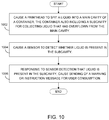
- FIG. 10 is a flow diagram depicting an example implementation of a method for collection of liquid ejected from a printhead.
- an issue of issue of dried ink and other contaminants accumulating at printhead nozzles is addressed by periodically causing the printheads nozzles to spit ink into an ink collection container.
- the collection container (sometimes referred to as a spittoon) is a consumable, such that when the collection container is filled with ink it is to be removed and discarded, to be replaced with a new collection container.
- the printing system should have an accurate reading of when the ink collection container is full.
- Various systems and methods have been utilized to detect when overflow at the ink collection container is imminent.
- a drop counter tracks the amount of ink deposited in the ink collection container, with the drop counter data being used to estimate how much ink is present in the ink collection container.
- the system determines that the ink collection container is full according to the drop detector data, the system provides a user instruction to replace the container.
- the drop counter performs abnormally, or if an expected user event occurs that disrupts the drop counting procedure (e.g., a user replacing an ink collection container with a non-empty one), there is a substantial risk the spit ink will exceed the maximum volume of the ink collection container and cause an ink overflow into the printer.
- an expected user event e.g., a user replacing an ink collection container with a non-empty one
- the disposable container includes a sensor for determining a level of ink in the disposable container.
- the ink collection container may include a liquid detection sensor or a floating mechanism for detecting the ink level.
- Other systems may have a sensor external to the disposable ink collection container, the sensor to read an ink level through a wall of the ink collection container and to determine time for replacement by comparing the sensed ink level to a threshold level.
- These solutions depend upon very accurate positioning of the external sensor relative to the disposable ink collection container, with ink level sensing adding to the complexity and cost of the printer.
- the complexity of these systems can contribute to printer downtime, e.g. downtime associated with sensor alignment or other calibration processes, and downtime associated with failure of the sensitive ink level sensing components.
- a printhead is caused to spit a liquid into a main cavity of a container, the container also including a subcavity, sometimes referred to herein as an overflow pocket, for collecting liquid that has overflown from the main cavity.
- a sensor is caused to detect whether liquid is present in the subcavity. Responsive to sensor detection that liquid is present in the subcavity, a message is caused to be sent to a user interface for user consumption. The message is to inform a user that the container is due to be replaced and/or to instruct the user replace the container.
- the senor is situated outside the main cavity of the container and adjacent to a shared wall as between the main cavity and the subcavity.
- the sensor is an inductive sensor or a capacitive sensor to detect the presence of liquid inside the subcavity.
- calibration of the sensor is not required upon user replacement of the container with a new container.
- a liquid collection system includes a container that has a floor and a set of container walls, and an overflow pocket that is formed by a portion of at least one of the container walls and a connecting member.
- the container has a main cavity that is for collection of liquid that has been spit from a printhead.
- the overflow pocket is to collect liquid for detection by a sensor situated outside the container and adjacent the container wall portion.
- the disclosed method and system provides significant benefits relative to existing commercial solutions.
- the disclosed method and system reduce ink collection container overflows and thereby reduce the associated printer downtimes printer downtimes.
- User replacement of a full collection container is made easier, and takes less time, relative to existing systems that depend upon measuring a threshold level of ink in the liquid collection container.
- the disclosed method and system do not require an accurate position of the sensor relative to a threshold level of ink as do existing systems, and therefore the bill of materials cost for the system, and the number of major printhead servicing errors (e.g., occurrences of ink overflowing from the liquid collection container onto other printer components due to errant ink level readings) will be considerably reduced.
- FIGS. 1 and 2 depict examples of physical and logical components for implementing various examples.
- various components are identified as engines 208 and 210 .
- engines 208 and 210 focus is on each engine's designated function.
- the term engine refers generally to hardware and/or programming to perform a designated function.
- the hardware of each engine for example, may include one or both of a processor and a memory, while the programming may be code stored on that memory and executable by the processor to perform the designated function.
- FIG. 1 is a block diagram depicting an example of a system for collection of liquid ejected from a printhead.
- system 100 includes a container 102 and an overflow pocket 104 .
- Container 102 includes a floor, and a container wall that defines, or at least partially defines, a perimeter of container 102 .
- Overflow pocket 104 is formed by a connecting member and a portion of the one container wall.
- Overflow pocket 104 is to collect liquid that has overflown from a main cavity of container 102 .
- the collected liquid is to be detected by a sensor situated outside container 102 and adjacent the container wall portion.
- system 100 may, upon detection of the liquid collected in overflow pocket 104 , send a user warning or user instruction message that disposable container 102 is ready to be removed and replaced.
- FIG. 2 is a block diagram depicting another example of a system for collection of liquid ejected from a printhead.
- system 100 includes sensor 206 .
- sensor 206 may be a capacitive sensor for detecting liquid that has overflowed from a main cavity of container 102 into overflow pocket 104 .
- a “capacitive sensor” refers generally to a sensor that can detect the presence of an object, even a nonconductive object, according to dielectric constant of the object. This makes both non-metal and metal liquids (e.g. an ink containing particles of bronze, aluminum, copper, zinc, silver, and/or gold) suitable targets for the capacitive sensor.
- sensor 206 may detect the presence in the overflow pocket of a nonmetallic water-based ink, as may be used with thermal inkjet printheads.
- sensor 206 may be an inductive sensor.
- an “inductive sensor” refers generally to a sensor that utilizes a magnetic field to detect an object. This makes metal inks suitable targets for the inductive sensor.
- an inductive sensor 206 may detect the presence in the overflow pocket of a metallic water-based ink, as may be used with thermal inkjet printheads.
- sensor 206 may be any apparatus for detecting liquid in overflow pocket 104 that does not contact the liquid (e.g., any apparatus that uses contactless sensing).
- system 100 may include a spit engine 208 and an alert engine 210 .
- Spit engine 210 represents generally a combination of hardware and programming to cause a printhead to spit ink or other liquid, into a main cavity of container 102 .
- a “printhead” refers generally to a mechanism for ejection of a liquid.
- the ejected liquid is a print agent.
- Examples of printheads are drop on demand inkjet printheads, such as piezoelectric printheads and thermo resistive printheads. Some printheads may be part of a cartridge which also stores the fluid to be dispensed. Other printheads are standalone and are supplied with fluid by an off-axis fluid supply.
- print agent refers generally to any substance that can be applied upon a media by a printer during a printing operation, including but not limited to inks, primers and overcoat materials (such as a varnish).
- an “ink” refers generally to a fluid that is to be applied to a media during a printing operation to form an image upon the media.
- a “printer” refers generally to liquid inkjet printer, solid toner-based printer, liquid toner-based printer, or any other electronic device that is to print a plot. “Printer” includes any multifunctional electronic device that performs a function such as scanning and/or copying in addition to printing.
- Alert engine 210 represents generally a combination of hardware and programming to cause sensor 206 to detect whether liquid is present in overflow pocket 104 , wherein the liquid overflowed from the main cavity of container 102 into the overflow pocket.
- alert engine 210 Upon receiving data indicative that sensor 206 has detected liquid in overflow pocket 104 , alert engine 210 is to cause a user warning message or a user instruction be sent to a monitor, screen, speaker or other message output component for user consumption.
- alert engine 210 may receive the data directly from sensor 206 .
- alert engine 207 may receive the data from a memory or a processor.
- the user warning message or user instruction may be a message or instruction that container 102 is full of liquid should be removed from the printer, to be replaced with a new, empty liquid collection container.
- FIGS. 3A and 3B are simple schematic diagrams that illustrate top down views of examples of a system for collection of liquid ejected from a printhead.
- FIG. 3A provides an example of a disposable container 102 with a floor 302 and container walls 304 a 304 b 304 c 304 d .
- an overflow pocket 104 is formed by a portion 308 of the container floor, a portion 310 of one of the container walls 304 a , and a connecting member 306 .
- container wall portion 310 and connecting member 306 form a semi-circular or oval shaped overflow pocket 104 .
- FIG. 3A provides an example of a disposable container 102 with a floor 302 and container walls 304 a 304 b 304 c 304 d .
- an overflow pocket 104 is formed by a portion 308 of the container floor, a portion 310 of one of the container walls 304 a , and a connecting member 306 .
- container wall portion 310 and connecting member 306 form a rectangular shaped overflow pocket 104 .
- one or all of the components of the disposable container 102 e.g., container floor 302 , container walls container walls 304 a 304 b 304 c 304 d , overflow pocket 104 (formed by a portion 308 of the container floor 302 , a portion 310 of one of the container walls 304 a , and connecting member 306 ) may be a plastic or other polymer.
- any one or more of the components of disposable container 102 or overflow pocket 104 may be or include a glass, a metal, or an organic material.
- system 100 includes a sensor 206 situated outside disposable container 102 and adjacent the portion 310 of the container wall 304 a that forms overflow pocket 104 .
- Sensor 206 is to detect liquid in overflow pocket 104 , and to send a signal or message for a user to remove disposable container 102 from a printer and replace disposable container 102 with a new disposable container that does not contain liquid spit from printheads.
- sensor 206 is an inductive sensor or a capacitive sensor that is to detect the presence of liquid overflow pocket 104 , rather than determine a particular amount of liquid in overflow pocket 104 . As a result, in such particular examples user replacement of disposable container 102 with a new container does not require that sensor 206 be reset or calibrated.
- FIGS. 4A, 4B, and 4C are simple schematic diagrams that illustrate a top down view and profile views of examples of a system for collection of liquid ejected from a printhead.
- FIGS. 4A, 4B, and 4C provide examples of a disposable container 102 with a floor 302 and container walls 304 a 304 b 304 c 304 d .
- an overflow pocket 104 is formed by a portion 308 of the container floor, a portion 310 of one of the container walls 204 a , and a connecting member 306 (connecting member 306 is sometimes referred to herein as an overflow wall).
- container wall portion 310 and connecting member 306 form a rectangular shaped overflow pocket 104 .
- a sensor 206 is situated in the printer outside of disposable container 102 and adjacent to the portion 310 of the container wall 304 a that forms overflow pocket 104 .
- Sensor 206 is to detect liquid 402 (indicated by a dotted pattern in FIGS. 4A and 4B ) in overflow pocket 104 , and to send a signal or message for a user to remove container 102 from a printer and replace container 102 with a new disposable container that does not contain liquid spit from printheads.
- the walls 304 a 304 b 304 c 304 d of container 102 have a uniform height.
- Connecting member 306 extends upward from container floor 302 (e.g., portion 308 of container floor 302 ) and has a height 404 that is less than the height 406 of the portion 310 of container wall 304 a that is a boundary of overflow pocket 104 .
- the walls 304 a 304 b 304 c or 304 d may not have a consistent height.
- the wall 304 a with a portion 310 that forms overflow pocket 104 has a slope.
- the wall 304 a that has a portion that forms the overflow pocket might have a stepped or other irregular height.
- the connecting member 306 that extends upward from container floor 302 is to have a maximum height 404 that is less than the lowest point 408 of the portion 310 of the container wall 304 a that helps form overflow pocket 104 . In this manner is assured that the liquid 402 collected in overflow pocket 104 does not spill over the portion 310 of wall 304 a.
- FIGS. 5A and 5B are top down views of an example of a service station 500 system for servicing a printhead.
- Service station 500 includes a disposable container 102 .
- Disposable container 102 includes a main cavity 502 that is formed by first wall 504 a , second wall 504 b , third wall 504 c , a fourth wall 504 d , and a floor 302 .
- Each of the first, second, third, and fourth walls has a minimum height of at least “x.”
- Disposable container 102 includes a subcavity 104 that serves as an overflow pocket to the main cavity 502 .
- Subcavity 104 is formed by a portion 310 of first wall 504 a , by an overflow wall 306 with a height “y” that is less than “x”, and a portion of the floor 302 . Subcavity 104 is to collect spit liquid that has overflown from main cavity 502 of container 102 .
- service station 500 may include a sensor 206 situated outside disposable container 102 and adjacent to the portion 310 of first wall 504 a that partially defines subcavity 104 .
- Sensor 206 is to detect the collected liquid in subcavity 104 .
- sensor 206 may be positioned outside disposable container 102 upon a supporting member (not depicted in FIG. 5B ) or some other element of service station 100 such that sensor 206 is adjacent to subcavity 104 .
- sensor 206 is left undisturbed. In this manner sensor 206 remains in the correct position to operate in conjunction with a new, empty disposable container that a user installs to replace filled disposable container 102 .
- FIGS. 6A, 6B, and 6C are simple schematic diagrams that illustrate top down views of additional examples of a system 100 for collection of liquid ejected from a printhead.
- FIG. 6A provides an example of a disposable container 102 with a floor 302 and container walls 304 a 304 b 304 c 304 d .
- an overflow pocket 104 is formed by a portion 308 of the container floor, a first portion 310 of one of the container walls 304 a , a second portion 602 of a second of the container walls 304 b and a connecting member 306 .
- FIG. 6A provides an example of a disposable container 102 with a floor 302 and container walls 304 a 304 b 304 c 304 d .
- an overflow pocket 104 is formed by a portion 308 of the container floor, a first portion 310 of one of the container walls 304 a , a second portion 602 of a second of the container walls 304 b and
- first container wall portion 310 , second container wall portion 602 , and connecting member 306 form a semi-circular or oval shaped overflow pocket 104 .
- first container wall portion 310 , second container wall portion 602 , and connecting member 306 form a rectangular shaped overflow pocket 104 .
- first container wall portion 310 , second container wall portion 602 , and connecting member 306 form a triangle shaped overflow pocket 104 .
- one or all of the components of the disposable container 102 may be a plastic, another polymer, a glass, metal, or an organic material.
- system 100 may include a sensor 206 situated outside disposable container 102 and adjacent the first portion 310 of the container wall 304 a , or the second portion 602 of the container wall 304 b , that forms overflow pocket 104 .
- FIGS. 7A and 7B are simple schematic diagrams that illustrate a top down view and profile views of examples of a system for collection of liquid ejected from a printhead.
- an overflow pocket 104 is formed by a portion 308 of the container floor, a first portion 310 of one of the container walls 204 a , a second portion of another of the container walls 304 b , and a connecting member 306 .
- container wall portion 310 and connecting member 306 form a rectangular shaped overflow pocket 104 .
- sensor 206 is situated in the printer outside of disposable container 102 and adjacent to the first portion 310 of the container wall 304 a that forms overflow pocket 104 .
- the sensor may be situated outside of disposable container 102 and adjacent to second portion 602 of the container wall 304 b that forms overflow pocket 104 .
- Sensor 206 is to detect liquid 402 (indicated by a dotted pattern in FIGS. 7A and 7B ) in overflow pocket 104 , and to send a signal or message for a user to remove container 102 from a printer and replace container 102 with a new disposable container that does not contain liquid spit from printheads.
- FIGS. 8A and 8B are top down views of another example of a system for collection of liquid ejected from a printhead.
- Service station 800 includes a disposable container 102 .
- Disposable container 102 includes a main cavity 802 that is formed by first wall 804 a , second wall 804 b , third wall 804 c , a fourth wall 804 d , and a floor 802 .
- Each of the first, second, third, and fourth walls has a minimum height of at least “x.”
- Disposable container 102 includes a subcavity 104 to the main cavity 802 .
- Subcavity 104 is formed by a first portion 310 of first wall 804 a , a second portion 602 of second wall 804 b , by an overflow wall 306 with a height “y” that is less than “x”, and a portion of the floor 802 .
- Subcavity 104 is to collect spit liquid that has overflown from main cavity 802 of container 102 depicted in FIGS. 8A and 8B .
- Overflow wall 306 that extends upward from container floor 802 has a maximum height y that is less than the lowest point of any of the container walls 804 a 804 b 804 c 804 d .
- container walls 804 a 804 b 804 c 804 d of disposable container 102 have a uniform height.
- container walls 804 a 804 b 804 c and 804 d may have varying heights.
- Overflow wall 306 having height y that is less than the lowest of any of container walls 804 a 804 b 804 c and 804 d causes liquid 402 in main cavity 802 to into overflow pocket 104 before overflowing any of walls 804 a 804 b 804 c 804 d.
- spit engine 208 and alert engine 210 were described as combinations of hardware and programming. Engines 208 and 210 may be implemented in a number of fashions. Looking at FIG. 9 the programming may be processor executable instructions stored on a tangible memory resource 930 and the hardware may include a processing resource 940 for executing those instructions. Thus, memory resource 930 can be said to store program instructions that when executed by processing resource 940 implement system 100 of FIG. 2 .
- Memory resource 930 represents generally any number of memory components capable of storing instructions that can be executed by processing resource 940 .
- Memory resource 930 is non-transitory in the sense that it does not encompass a transitory signal but instead is made up of a memory component or memory components to store the instructions.
- Memory resource 930 may be implemented in a single device or distributed across devices.
- processing resource 940 represents any number of processors capable of executing instructions stored by memory resource 930 .
- Processing resource 940 may be integrated in a single device or distributed across devices. Further, memory resource 930 may be fully or partially integrated in the same device as processing resource 940 , or it may be separate but accessible to that device and processing resource 940 .
- the program instructions can be part of an installation package that when installed can be executed by processing resource 940 to implement system 100 .
- memory resource 930 may be a portable medium such as a CD, DVD, or flash drive or a memory maintained by a server from which the installation package can be downloaded and installed.
- the program instructions may be part of an application or applications already installed.
- memory resource 930 can include integrated memory such as a hard drive, solid state drive, or the like.
- the executable program instructions stored in memory resource 930 are depicted as spit module 908 and alert module 910 .
- Spit module 908 represents program instructions that when executed by processing resource 940 may perform any of the functionalities described above in relation to alert engine 208 of FIG. 2 .
- Alert module 910 represents program instructions that when executed by processing resource 940 may perform any of the functionalities described above in relation to alert engine 210 of FIG. 2 .
- FIG. 10 is a flow diagram of implementation of a method for collection of liquid ejected from a printhead.
- a printhead is caused to spit a liquid into a main cavity of a container.
- the container also includes a subcavity or overflow pocket for collecting liquid that has overflown from the main cavity (block 1002 ).
- spit engine 208 FIG. 1
- spit module 908 FIG. 9
- a sensor is caused to detect whether liquid is present in the subcavity (block 1004 ).
- alert engine 210 FIG. 1
- alert module 910 FIG. 9
- processing resource 940 may be responsible for implementing block 1004 .
- alert engine 210 ( FIG. 1 ) or alert module 910 ( FIG. 9 ), when executed by processing resource 940 , may be responsible for implementing block 1006 .
- FIGS. 1, 2, 3A, 3B, 4A-4C, 5A and 5B, 6A-6C, 7A and 7B, 8A and 8B, 9, and 10 aid in depicting the architecture, functionality, and operation of various examples.
- FIGS. 1, 2, 3A, 3B, 4A-4C, 5A and 5B, 6A-6C, 7A and 7B, 8A and 8B , and 9 depict various physical and logical components.
- Various components are defined at least in part as programs or programming. Each such component, portion thereof, or various combinations thereof may represent in whole or in part a module, segment, or portion of code that comprises executable instructions to implement any specified logical function(s).
- Each component or various combinations thereof may represent a circuit or a number of interconnected circuits to implement the specified logical function(s). Examples can be realized in a memory resource for use by or in connection with a processing resource.
- a “processing resource” is an instruction execution system such as a computer/processor based system or an ASIC (Application Specific Integrated Circuit) or other system that can fetch or obtain instructions and data from computer-readable media and execute the instructions contained therein.
- a “memory resource” is a non-transitory storage media that can contain, store, or maintain programs and data for use by or in connection with the instruction execution system. The term “non-transitory” is used only to clarify that the term media, as used herein, does not encompass a signal.
- the memory resource can comprise a physical media such as, for example, electronic, magnetic, optical, electromagnetic, or semiconductor media.
- suitable computer-readable media include, but are not limited to, hard drives, solid state drives, random access memory (RAM), read-only memory (ROM), erasable programmable read-only memory (EPROM), flash drives, and portable compact discs.
- FIG. 10 shows specific orders of execution, the order of execution may differ from that which is depicted.
- the order of execution of two or more blocks or arrows may be scrambled relative to the order shown.
- two or more blocks shown in succession may be executed concurrently or with partial concurrence. Such variations are within the scope of the present disclosure.
Landscapes
- Ink Jet (AREA)
- Engineering & Computer Science (AREA)
- Environmental & Geological Engineering (AREA)
Abstract
Description
Claims (9)
Applications Claiming Priority (3)
| Application Number | Priority Date | Filing Date | Title |
|---|---|---|---|
| EP19154487.3A EP3689616A1 (en) | 2019-01-30 | 2019-01-30 | Collection of liquid ejected from a printhead |
| EP19154487.3 | 2019-01-30 | ||
| EP19154487 | 2019-01-30 |
Publications (2)
| Publication Number | Publication Date |
|---|---|
| US20200238712A1 US20200238712A1 (en) | 2020-07-30 |
| US11214070B2 true US11214070B2 (en) | 2022-01-04 |
Family
ID=65268803
Family Applications (1)
| Application Number | Title | Priority Date | Filing Date |
|---|---|---|---|
| US16/743,936 Active 2040-04-04 US11214070B2 (en) | 2019-01-30 | 2020-01-15 | Collection of liquid ejected from a printhead |
Country Status (2)
| Country | Link |
|---|---|
| US (1) | US11214070B2 (en) |
| EP (1) | EP3689616A1 (en) |
Citations (14)
| Publication number | Priority date | Publication date | Assignee | Title |
|---|---|---|---|---|
| US6293641B1 (en) * | 1997-06-06 | 2001-09-25 | Sharp Kabushiki Kaisha | Recording apparatus for periodically emitting recording materials by material specific emission amount |
| US6337959B1 (en) | 1999-11-24 | 2002-01-08 | Samsung Electronics Co., Ltd. | Liquid level detector and liquid level measuring apparatus of printer adopting the same |
| US20040104959A1 (en) | 2000-10-31 | 2004-06-03 | Brown Steven Robert | Printing apparatus |
| US6943566B2 (en) | 2000-12-20 | 2005-09-13 | Abertax Research And Development Ltd. | Method and device for measuring levels |
| EP1691177A1 (en) | 2005-02-11 | 2006-08-16 | Mutoh Europe N.V. | System for identifying an ink and detecting the level of said ink in a tank with capacitive sensors |
| US20060181569A1 (en) * | 2005-02-16 | 2006-08-17 | Yasuhiro Kawashima | Image forming apparatus |
| US20090040262A1 (en) * | 2007-02-23 | 2009-02-12 | Toshiaki Watanabe | Remaining amount detection sensor and ink-jet printer using the same |
| US7814582B2 (en) | 2003-12-31 | 2010-10-19 | Kimberly-Clark Worldwide, Inc. | System and method for measuring and monitoring overflow or wetness conditions in a washroom |
| US8841926B2 (en) | 2006-01-20 | 2014-09-23 | Phoenix Contact Gmbh & Co. Kg | Method, liquid supply unit, and measurement device for a level indicator |
| US9079414B2 (en) | 2010-11-19 | 2015-07-14 | Domino Printing Sciences Plc | Inkjet printers |
| WO2015159659A1 (en) | 2014-04-17 | 2015-10-22 | 富士フイルム株式会社 | Inkjet recording device |
| US20170106687A1 (en) | 2015-10-14 | 2017-04-20 | Seiko Epson Corporation | Waste liquid container |
| US20170106656A1 (en) * | 2015-10-20 | 2017-04-20 | Heidelberger Druckmaschinen Ag | Digital printing machine and disposable spittoon |
| US20190193405A1 (en) * | 2017-12-25 | 2019-06-27 | Roland Dg Corporation | Inkjet printer |
Family Cites Families (1)
| Publication number | Priority date | Publication date | Assignee | Title |
|---|---|---|---|---|
| WO2018230275A1 (en) * | 2017-06-15 | 2018-12-20 | 富士フイルム株式会社 | Moisturizing device, maintenance device, and liquid discharge device |
-
2019
- 2019-01-30 EP EP19154487.3A patent/EP3689616A1/en not_active Withdrawn
-
2020
- 2020-01-15 US US16/743,936 patent/US11214070B2/en active Active
Patent Citations (16)
| Publication number | Priority date | Publication date | Assignee | Title |
|---|---|---|---|---|
| US6293641B1 (en) * | 1997-06-06 | 2001-09-25 | Sharp Kabushiki Kaisha | Recording apparatus for periodically emitting recording materials by material specific emission amount |
| US6337959B1 (en) | 1999-11-24 | 2002-01-08 | Samsung Electronics Co., Ltd. | Liquid level detector and liquid level measuring apparatus of printer adopting the same |
| US20040104959A1 (en) | 2000-10-31 | 2004-06-03 | Brown Steven Robert | Printing apparatus |
| US7419239B2 (en) | 2000-10-31 | 2008-09-02 | Zipher Limited | Printing apparatus |
| US6943566B2 (en) | 2000-12-20 | 2005-09-13 | Abertax Research And Development Ltd. | Method and device for measuring levels |
| US7814582B2 (en) | 2003-12-31 | 2010-10-19 | Kimberly-Clark Worldwide, Inc. | System and method for measuring and monitoring overflow or wetness conditions in a washroom |
| EP1691177A1 (en) | 2005-02-11 | 2006-08-16 | Mutoh Europe N.V. | System for identifying an ink and detecting the level of said ink in a tank with capacitive sensors |
| US20060181569A1 (en) * | 2005-02-16 | 2006-08-17 | Yasuhiro Kawashima | Image forming apparatus |
| US8841926B2 (en) | 2006-01-20 | 2014-09-23 | Phoenix Contact Gmbh & Co. Kg | Method, liquid supply unit, and measurement device for a level indicator |
| US7798586B2 (en) | 2007-02-23 | 2010-09-21 | Sii Printek Inc. | Remaining amount detection sensor and ink-jet printer using the same |
| US20090040262A1 (en) * | 2007-02-23 | 2009-02-12 | Toshiaki Watanabe | Remaining amount detection sensor and ink-jet printer using the same |
| US9079414B2 (en) | 2010-11-19 | 2015-07-14 | Domino Printing Sciences Plc | Inkjet printers |
| WO2015159659A1 (en) | 2014-04-17 | 2015-10-22 | 富士フイルム株式会社 | Inkjet recording device |
| US20170106687A1 (en) | 2015-10-14 | 2017-04-20 | Seiko Epson Corporation | Waste liquid container |
| US20170106656A1 (en) * | 2015-10-20 | 2017-04-20 | Heidelberger Druckmaschinen Ag | Digital printing machine and disposable spittoon |
| US20190193405A1 (en) * | 2017-12-25 | 2019-06-27 | Roland Dg Corporation | Inkjet printer |
Also Published As
| Publication number | Publication date |
|---|---|
| US20200238712A1 (en) | 2020-07-30 |
| EP3689616A1 (en) | 2020-08-05 |
Similar Documents
| Publication | Publication Date | Title |
|---|---|---|
| US9079414B2 (en) | Inkjet printers | |
| US11090942B2 (en) | Fluid ejection dies including strain gauge sensors | |
| US11084282B2 (en) | Fluid ejection dies including strain gauge sensors | |
| EP2867732B1 (en) | Refilled toner cartridge having increased yield | |
| US10308034B2 (en) | Liquid container, liquid remaining amount detection circuit of liquid container, liquid remaining amount detection method, liquid container identification method, ink mounting unit, printer, and print system | |
| CN103619605A (en) | Ink level sensor and related methods | |
| US9889642B2 (en) | Managing printhead nozzle conditions | |
| US10479091B2 (en) | Liquid discharge apparatus and waste liquid amount detection method | |
| CN113442576B (en) | Liquid level detection device and image forming apparatus | |
| US11214070B2 (en) | Collection of liquid ejected from a printhead | |
| US8246132B2 (en) | Image forming systems and methods thereof | |
| CN101308359B (en) | Method and apparatus for storing information for the mount of a toner, and an image forming apparatus | |
| US8596734B2 (en) | Fluid ejection system and methods thereof | |
| US8550616B2 (en) | Method of monitoring gel accumulation in a drum maintenance unit | |
| US10955299B2 (en) | Fluid ejection dies including strain gauge sensors | |
| JP2015118174A5 (en) | ||
| JP4670288B2 (en) | Liquid ejector | |
| CN109641464B (en) | Method and apparatus for estimating the number of pages that can be printed | |
| US11209303B2 (en) | Filling level detection in a printing fluid waste container | |
| JP2016048345A (en) | Apparatus and method for detecting amount of toner conveyed, and program for toner conveyance amount detection apparatus | |
| EP1184181A1 (en) | Method and system for determining usage of a print solution for a print operation | |
| CN110271293A (en) | Ink supply unit, inkjet recording device and ink feed method | |
| WO2025094607A1 (en) | Remaining quantity management device | |
| WO2025070117A1 (en) | Remaining amount management device | |
| WO2021154296A1 (en) | Printbar contact calibration |
Legal Events
| Date | Code | Title | Description |
|---|---|---|---|
| FEPP | Fee payment procedure |
Free format text: ENTITY STATUS SET TO UNDISCOUNTED (ORIGINAL EVENT CODE: BIG.); ENTITY STATUS OF PATENT OWNER: LARGE ENTITY |
|
| STPP | Information on status: patent application and granting procedure in general |
Free format text: DOCKETED NEW CASE - READY FOR EXAMINATION |
|
| AS | Assignment |
Owner name: HP PRINTING AND COMPUTING SOLUTIONS, S.L.U., STATELESS Free format text: ASSIGNMENT OF ASSIGNORS INTEREST;ASSIGNORS:BORREGO LEBRATO, ALBERTO;LLUCH, JORDI;GROS, XAVIER;SIGNING DATES FROM 20190122 TO 20190228;REEL/FRAME:052507/0608 Owner name: HP SCITEX LTD., ISRAEL Free format text: ASSIGNMENT OF ASSIGNORS INTEREST;ASSIGNORS:LEVIN, ALON;HP PRINTING AND COMPUTING SOLUTIONS, S.L.U.;SIGNING DATES FROM 20190124 TO 20190212;REEL/FRAME:052506/0218 |
|
| STPP | Information on status: patent application and granting procedure in general |
Free format text: NON FINAL ACTION MAILED |
|
| STPP | Information on status: patent application and granting procedure in general |
Free format text: RESPONSE TO NON-FINAL OFFICE ACTION ENTERED AND FORWARDED TO EXAMINER |
|
| STPP | Information on status: patent application and granting procedure in general |
Free format text: NOTICE OF ALLOWANCE MAILED -- APPLICATION RECEIVED IN OFFICE OF PUBLICATIONS |
|
| STPP | Information on status: patent application and granting procedure in general |
Free format text: PUBLICATIONS -- ISSUE FEE PAYMENT VERIFIED |
|
| STCF | Information on status: patent grant |
Free format text: PATENTED CASE |
|
| MAFP | Maintenance fee payment |
Free format text: PAYMENT OF MAINTENANCE FEE, 4TH YEAR, LARGE ENTITY (ORIGINAL EVENT CODE: M1551); ENTITY STATUS OF PATENT OWNER: LARGE ENTITY Year of fee payment: 4 |