US11213914B2 - Laser processing method and method of manufacturing display apparatus - Google Patents
Laser processing method and method of manufacturing display apparatus Download PDFInfo
- Publication number
- US11213914B2 US11213914B2 US15/422,847 US201715422847A US11213914B2 US 11213914 B2 US11213914 B2 US 11213914B2 US 201715422847 A US201715422847 A US 201715422847A US 11213914 B2 US11213914 B2 US 11213914B2
- Authority
- US
- United States
- Prior art keywords
- laser beams
- laser
- transmission plate
- adjusting
- laser beam
- Prior art date
- Legal status (The legal status is an assumption and is not a legal conclusion. Google has not performed a legal analysis and makes no representation as to the accuracy of the status listed.)
- Active, expires
Links
Images


Classifications
-
- B—PERFORMING OPERATIONS; TRANSPORTING
- B23—MACHINE TOOLS; METAL-WORKING NOT OTHERWISE PROVIDED FOR
- B23K—SOLDERING OR UNSOLDERING; WELDING; CLADDING OR PLATING BY SOLDERING OR WELDING; CUTTING BY APPLYING HEAT LOCALLY, e.g. FLAME CUTTING; WORKING BY LASER BEAM
- B23K26/00—Working by laser beam, e.g. welding, cutting or boring
- B23K26/02—Positioning or observing the workpiece, e.g. with respect to the point of impact; Aligning, aiming or focusing the laser beam
- B23K26/06—Shaping the laser beam, e.g. by masks or multi-focusing
- B23K26/067—Dividing the beam into multiple beams, e.g. multifocusing
- B23K26/0676—Dividing the beam into multiple beams, e.g. multifocusing into dependently operating sub-beams, e.g. an array of spots with fixed spatial relationship or for performing simultaneously identical operations
-
- B—PERFORMING OPERATIONS; TRANSPORTING
- B23—MACHINE TOOLS; METAL-WORKING NOT OTHERWISE PROVIDED FOR
- B23K—SOLDERING OR UNSOLDERING; WELDING; CLADDING OR PLATING BY SOLDERING OR WELDING; CUTTING BY APPLYING HEAT LOCALLY, e.g. FLAME CUTTING; WORKING BY LASER BEAM
- B23K26/00—Working by laser beam, e.g. welding, cutting or boring
- B23K26/02—Positioning or observing the workpiece, e.g. with respect to the point of impact; Aligning, aiming or focusing the laser beam
- B23K26/06—Shaping the laser beam, e.g. by masks or multi-focusing
- B23K26/064—Shaping the laser beam, e.g. by masks or multi-focusing by means of optical elements, e.g. lenses, mirrors or prisms
Definitions
- One or more embodiments relate to a laser processing method and method of manufacturing a display apparatus, and more particularly, to a laser processing method capable of performing various types of processing while reducing a need to change components and method of manufacturing a display apparatus by using the laser processing method.
- masks having various shaped openings are used to form various patterns in manufacturing electronic devices.
- an organic material needs to be deposited on a predetermined area.
- deposition is performed by using a mask having openings corresponding to the predetermined area. Therefore, the mask having the corresponding openings needs to be manufactured.
- the mask is manufactured by irradiating a laser beam to a predetermined area of, for example, a metal thin plate, in order to form the openings.
- a structure of the laser processing apparatus has to be changed whenever a shape of a processing target to be manufactured is changed.
- One or more embodiments include a laser processing method capable of performing various types of processing while reducing a need to change components, and method of manufacturing a display apparatus by using the laser processing method.
- a laser processing method includes: splitting a laser beam emitted from a laser beam source into a plurality of laser beams by using a laser beam splitter; and transmitting at least two of the plurality of laser beams through a position adjustment equipment that is on paths of the at least two laser beams in order to adjust a distance between the at least two laser beams by using a difference between a refractive index of an element of the position adjustment equipment and a refractive index of a peripheral environment.
- the adjusting of the distance may include transmitting the at least two laser beams through a flexible transmission plate included in the position adjustment unit.
- the laser processing method may further include adjusting degree of bending of the flexible transmission plate.
- the adjusting degree of bending of the flexible transmission plate may be performed by adjusting positions of a plurality of adjustment pins included in the position adjustment unit.
- the laser processing method may further include adjusting local curvatures of the flexible transmission plate at a plurality of locations.
- the adjusting local curvatures of the flexible transmission plate at a plurality of locations may be performed by adjusting positions of a plurality of adjustment pins included in the position adjustment unit.
- the adjusting of the distance may include transmitting the at least two laser beams through the position adjustment equipment in parallel with each other.
- the adjusting of the distance may include transmitting all of the plurality of laser beams through the position adjustment unit.
- the laser processing method may further include irradiating the laser beams having an adjusted distance therebetween onto a processing target.
- the laser processing method may further include forming a plurality of openings at a same time by irradiating the laser beams having an adjusted distance therebetween onto a sheet.
- a method of manufacturing a display apparatus includes: splitting a laser beam emitted from a laser beam source into a plurality of laser beams by using a laser beam splitter; transmitting at least two of the plurality of laser beams through a position adjustment equipment that is on paths of the at least two laser beams in order to adjust a distance between the at least two laser beams by using a difference between a refractive index of the position adjustment equipment and a refractive index of a peripheral environment; forming a plurality of openings at the same time by irradiating the laser beams having an adjusted distance therebetween onto a sheet; and forming a patterned layer on a substrate by passing an evaporation material though the plurality of openings of the sheet.
- the adjusting of the distance may include transmitting the at least two laser beams through a flexible transmission plate included in the position adjustment unit.
- the method may further include adjusting degree of bending of the flexible transmission plate.
- the method may further include adjusting local curvatures of the flexible transmission plate at a plurality of locations.
- the adjusting of the distance may include transmitting the at least two laser beams through the position adjustment equipment in parallel with each other.
- the adjusting of the distance may include transmitting all of the plurality of laser beams through the position adjustment unit.
- FIG. 1 is a conceptual diagram schematically illustrating a laser processing apparatus according to an embodiment and a processing target;
- FIG. 2 is a conceptual diagram schematically showing a change in a path of a laser beam in a part of the laser processing apparatus of FIG. 1 ;
- FIG. 3 is a graph schematically illustrating a compensation degree of a laser beam by the laser processing apparatus of FIG. 1 ;
- FIG. 4 is a schematic conceptual diagram of laser beams having distortion in some paths
- FIG. 5 is a schematic conceptual diagram illustrating compensation for the distortion of FIG. 4 ;
- FIG. 6 is a schematic conceptual diagram of laser beams, distortion of which is compensated for in FIG. 5 ;
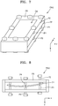
- FIG. 7 and FIG. 8 are respectively a perspective view and a side view of a position adjustment equipment in a laser processing apparatus according to an embodiment
- FIG. 9 is a schematic conceptual diagram of a laser processing apparatus according to an embodiment and a processing target.
- FIG. 10 is a schematic conceptual diagram of a laser processing apparatus according to an embodiment and a processing target.
- an x-axis, a y-axis and a z-axis are not limited to three axes of the rectangular coordinate system, and may be interpreted in a broader sense.
- the x-axis, the y-axis, and the z-axis may be perpendicular to one another, or may represent different directions that are not perpendicular to one another.
- FIG. 1 is a schematic conceptual diagram of a laser processing apparatus according to an embodiment and a processing target.
- the laser processing apparatus according to the embodiment includes a laser beam source (LBS), a laser beam splitter (LBSU), and a position adjustment equipment (PAU).
- LBS laser beam source
- LBSU laser beam splitter
- PAU position adjustment equipment
- the laser beam source LBS may emit a laser beam.
- the laser beam splitter LBSU is located on a path of a laser beam LB emitted from the laser beam source LBS. Accordingly, the laser beam splitter LBSU splits the laser beam LB into a plurality of laser beams LB 1 , LB 2 , LB 3 , and LB 4 .
- the laser beam splitter LBSU may include a diffractive optical element lens.
- the position adjustment equipment PAU is located on paths of at least two laser beams from among the plurality of laser beams LB 1 , LB 2 , LB 3 , and LB 4 behind the laser beam splitter LBSU.
- a transmission plate TP included in the position adjustment equipment PAU is located on paths of all of the plurality of laser beams LB 1 , LB 2 , LB 3 , and LB 4 . That is, all of the plurality of laser beams LB 1 , LB 2 , LB 3 , and LB 4 pass through the transmission plate TP of the position adjustment equipment PAU in FIG. 1 .
- Laser beams LB 1 ′, LB 2 ′, LB 3 ′, and LB 4 ′ that have passed through the position adjustment equipment PAU reach a processing target WP.
- the position adjustment equipment PAU may adjust a distance between at least two laser beams passing therethrough, by using a difference between a refractive index of at least one element thereof and a refractive index of a peripheral environment.
- FIG. 2 is a schematic conceptual diagram showing a variation in a path of a laser beam in the transmission plate TP of the laser processing apparatus of FIG. 1 .
- the laser beam LB 1 proceeding in a +z direction changes the path thereof while passing through the transmission plate TP due to a difference between the refractive indexes of the transmission plate TP and the peripheral environment. Accordingly, as shown in FIG.
- a position of the laser beam LB 1 ′ on an xy-plane after passing through the transmission plate TP is different from that of the laser beam LB 1 on the xy-plane before passing through the transmission plate TP.
- a distance h on a surface of the transmission plate TP between an extension (dashed-dot line of FIG. 2 ) of the path of the laser beam LB 1 before passing through the transmission plate TP having a thickness t and the path of the laser beam LB 1 ′ after passing through the transmission plate TP may be expressed by the following Equation 2.
- Equation 2 Equation 2
- a distance d between an extension (dashed-dot line of FIG. 2 ) of the path of the laser beam LB 1 before passing through the transmission plate TP and the path of the laser beam LB 1 ′ after passing through the transmission plate TP may be expressed by the following Equation 3.
- Equation 3 when values of ⁇ I and ⁇ r are sufficiently small, the above Equation 3 may be approximated as the following Equation 4.
- a position correction distance d between the laser beam LB 1 before passing through the transmission plate TP and the laser beam LB 1 ′ after passing through the transmission plate TP may be defined by using the thickness t of the transmission plate TP, the refractive index n 2 of the transmission plate TP, the refractive index n 1 of the peripheral environment, and the incident angle ⁇ i of the laser beam LB 1 to the transmission plate TP.
- the position correction distance d may be interpreted as a function of ⁇ i , that is, an inclination degree of the transmission plate TP. That is, the difference between the laser beam LB 1 before passing through the transmission plate TP and the laser beam LB 1 ′ after passing through the transmission plate TP on the xy-plane may be adjusted according to the inclination degree of the transmission plate TP.
- FIG. 3 is a graph schematically showing a degree of correcting the laser beam by the laser processing apparatus of FIG. 1 .
- the inclination of the transmission plate TP that is, the incident angle of the laser beam LB 1 , varies depending on each point of the transmission plate TP, and accordingly, a degree of correcting the laser beam varies.
- the graph of FIG. 3 shows that the transmission plate TP is curved, the inclination of the transmission plate TP, that is, the incident angle of the laser beam LB 1 , varies depending on each point of the transmission plate TP, and accordingly, a degree of correcting the laser beam varies.
- a longitudinal axis at the left side denotes an inclination angle of the laser beam LB 1 to each point on the transmission plate TP having a refractive index of 1.5 and a thickness of 0.1 mm
- a longitudinal axis at the right side denotes a position variation amount (unit: mm) between the laser beam LB 1 and the laser beam LB 1 ′ as the laser beam LB 1 passes through each point of the transmission plate TP.
- numbers of a transverse axis are understood to represent locations where the laser beams are incident in the transmission plate TP.
- the distance between the laser beams may be adjusted simply by adjusting the position adjustment unit, without manipulating the laser beam source LBS, the laser beam splitter LBSU, or the other optical elements. Accordingly, even if a shape of the processing target or processing conditions are changed, laser processing may be implemented simply in correspondence with the changes.
- the openings are formed by irradiating a laser beam to the preset locations in a metal thin plate.
- locations of the openings formed during manufacturing of the mask are changed as well.
- the laser processing apparatus according to the prior art has to adjust locations of the laser beams by correcting the laser beam splitter having a complicated structure.
- the distance between the laser beams may be adjusted only by adjusting the position adjustment equipment, and in particular, by adjusting a degree of bending or local curvatures of the transmission plate TP by adjusting the position adjustment equipment PAU.
- the local curvatures denote a plurality of curvatures of the transmission plate TP at a plurality of locations.
- the plurality of curvatures of the transmission plate TP at a plurality of locations may be adjusted by adjusting positions of the plurality of adjustment pins P 1 through P 4 included in the position adjustment equipment PAU.
- the laser processing apparatus of the embodiment even when abnormal situation occurs in the laser beam splitter LBSU or other optical elements and an error occurs in the location of at least one of the laser beams LB 1 , LB 2 , LB 3 , and LB 4 , there is no need to replace or repair the laser beam splitter LBSU or the optical elements that are complicated and relatively expensive. That is, the location of the laser beam having an error from among the laser beams LB 1 , LB 2 , LB 3 , and LB 4 may be effectively corrected by adjusting the degree of incline or angle of curvature of the transmission plate TP of the position adjustment equipment PAU in the laser processing apparatus of the present embodiment.
- FIG. 4 is a schematic conceptual diagram of laser beams LB 1 , LB 2 , LB 3 , LB 4 , and LB 5 having distortions in some paths thereof.
- the paths of the laser beams LB 1 , LB 2 , LB 3 , LB 4 , and LB 5 need to be constant, the laser beam LB 5 may be mis-aligned in a ⁇ x direction and a +y direction as shown in FIG. 4 , and then, the position of the laser beam LB 5 may be corrected by using the transmission plate TP of the position adjustment equipment PAU as shown in FIG. 5 .
- the laser beams LB 1 , LB 2 , LB 3 , and LB 4 whose positions are correct, are incident nearly perpendicularly to the transmission plate TP, and only a part of the transmission plate TP, through which the laser beam LB 5 having the wrong position passes, is curved.
- a position of a laser beam LB 5 ′, after passing through the transmission plate TP may be corrected as shown in FIG. 6 .
- the position adjustment equipment PAU may have various structures, such as the structures shown in FIG. 7 , which is a perspective view, and in FIG. 8 , which is a side view.
- the position adjustment equipment PAU may include a frame FR, the transmission plate TP, and a plurality of adjustment pins P 1 , P 2 , P 3 , and P 4 .
- the frame FR may have various shapes.
- the frame FR may have a space in which the transmission plate TP is to be located therein as shown in FIGS. 7 and 8 .
- the frame FR may have an opening area OA so that the laser beams may be incident to the transmission plate TP.
- the frame FR includes a plurality of through holes, through which the adjustment pins P 1 , P 2 , P 3 , and P 4 may be inserted.
- the through holes may have screw threads in an internal surface thereof, so that the adjustment pins P 1 , P 2 , P 3 , and P 4 may be screwed to the frame FR. Degrees of inserting the adjustment pins P 1 , P 2 , P 3 , and P 4 in the frame FR may be adjusted.
- positions of at least two adjustment pins from among the plurality of adjustment pins P 1 , P 2 , P 3 , and P 4 are differently adjusted from the others, and thus, a curved angle of the transmission plate TP may be simply and exactly adjusted.
- end portions of the adjustment pins P 1 and P 2 that are located above and below the transmission plate TP respectively, contact the transmission plate TP in a first point of the transmission plate TP
- end portions of the adjustment pins P 3 and P 4 that are located above and below the transmission plate TP contact the transmission plate TP tin a second point to be different from the first point so as to adjust the curved angle of the transmission plate TP.
- a portion to be curved in the transmission plate TP and the curved angle of the transmission plate TP may be easily adjusted by adjusting the insertion degrees of the adjustment pins P 1 , P 2 , P 3 , and P 4 in the frame FR.
- the transmission plate TP may be flexible.
- the position adjustment equipment PAU may be located at various locations in the laser processing apparatus, provided that the various locations are behind the laser beam splitter LBSU.
- the position adjustment equipment PAU may be located so that at least two laser beams transmitting through the position adjustment equipment PAU may be incident thereto in parallel with each other.
- a plurality of laser beams split by the laser beam splitter LBSU in parallel with each other are incident to the position adjustment equipment PAU, and after that, the plurality of laser beams are irradiated to the processing target WP via a first optical element OP 1 , a scanning unit SU, and a second optical element OP 2 .
- the scanning unit SU may include, for example, a reflection plate, and change a proceeding direction of the laser beams.
- the position adjustment equipment PAU may be located so that the laser beams split by the laser beam splitter LBSU may be incident to the position adjustment equipment PAU when the laser beams are in parallel with one another after passing through the first optical element OP 1 , the scanning unit SU, and the second optical element OP 2 , and before being irradiated to the processing target WP.
- the laser beams when the laser beams are incident to the position adjustment equipment PAU in a state where the laser beams are in parallel with each other, it may be easily determined which part of the transmission plate TP of the position adjustment equipment PAU and how much adjustment are needed.
- the laser processing apparatus is described as above, but one or more embodiments are not limited thereto.
- a laser processing method using the laser processing apparatus may be included in a scope of the inventive concept.
- the laser beam LB emitted from the laser beam source LBS is split into the plurality of laser beams LB 1 , LB 2 , LB 3 , and LB 4 by the laser beam splitter LBSU, as shown in FIG. 1 .
- the position adjustment equipment PAU is located on the path of at least two of the plurality of laser beams LB 1 , LB 2 , LB 3 , and LB 4 , so that the at least two laser beams pass through the position adjustment equipment PAU and distances between the laser beams LB 1 ′, LB 2 ′, LB 3 ′, and LB 4 ′ that passed through the transmission plate TP in the position adjustment equipment PAU may be modified by using the difference between the refractive indexes. Adjusting of the distance may be a process in which the at least two laser beams pass through the transmission plate TP that is flexible in the position adjustment equipment PAU. After that, a process of irradiating the laser beams LB 1 ′, LB 2 ′, LB 3 ′, and LB 4 ′, distances of which are adjusted, onto the processing target WP.
- a distance difference on the xy-plane between the laser beam LB 1 before passing through the transmission plate TP and the laser beam LB 1 ′ after passing through the transmission plate TP may be adjusted as shown in FIG. 2 only by adjusting the transmission plate TP.
- the positions of the plurality of adjustment pins P 1 , P 2 , P 3 , and P 4 included in the position adjustment equipment PAU are adjusted to adjust the curved angle of the transmission plate TP, and then, a correction degree of the distances among the laser beams LB 1 ′, LB 2 ′, LB 3 ′, and LB 4 ′ passed through the transmission plate TP may be determined.
- the adjusting of distances among the laser beams may be a process of transmitting at least two laser beams through the position adjustment equipment PAU in parallel with each other.
- the plurality of laser beams that are split by the laser beam splitter LBSU in parallel with each other are incident to the position adjustment equipment PAU, and after that, are irradiated to the processing target WP via the first optical element OP 1 , the scanning unit SU, and the second optical element OP 2 .
- the plurality of laser beams that are split by the laser beam splitter LBSU in parallel with each other are incident to the position adjustment equipment PAU, and after that, are irradiated to the processing target WP via the first optical element OP 1 , the scanning unit SU, and the second optical element OP 2 .
- the laser beams split by the laser beam splitter LBSU may be incident to the position adjustment equipment PAU before being irradiated onto the processing target WP when they are in parallel with each other after passing through the first optical element OP 1 , the scanning unit SU, and the second optical element OP 2 .
- the laser beams when the laser beams are incident to the position adjustment equipment PAU in parallel with each other, a position of the transmission plate TP in the position adjustment equipment PAU, an amount and a direction of adjustment are easily determined.
- the adjusting of the distance may be a process of transmitting the plurality of laser beams through the position adjustment unit.
- a laser beam that does not need to be adjusted may be nearly perpendicularly incident to the transmission plate TP to maintain the original path, and a laser beam that needs to be adjusted is incident to the transmission plate TP to be inclined so as to correct the path.
- a process of irradiating the laser beams having adjusted distances onto a metal sheet so as to form a plurality of openings at the same time may be performed to manufacture a deposition metal mask.
- the laser processing method and apparatus capable of performing the processing in various types while reducing change in the components may be implemented.
- a scope of the one or more embodiments is not limited thereto.
- the laser processing method is described as above, but one or more embodiments are not limited thereto.
- method of manufacturing a display apparatus using the laser processing method may be included in a scope of the present disclosure.
- a mask having a plurality of openings is necessary to manufacture a display apparatus.
- Such mask may be used to form a patterned layer on a substrate by passing an evaporation material through the plurality of openings of the mask.
- a mask produced by using the laser processing method can be used.
- the method of manufacturing a display apparatus may include: splitting a laser beam emitted from a laser beam source into a plurality of laser beams by using a laser beam splitter; transmitting at least two of the plurality of laser beams through a position adjustment equipment that is on paths of the at least two laser beams in order to adjust a distance between the at least two laser beams by using a difference between a refractive index of the position adjustment equipment and a refractive index of a peripheral environment; forming a plurality of openings at a same time by irradiating the laser beams having an adjusted distance therebetween onto a sheet; and forming a patterned layer on a substrate by passing an evaporation material though the plurality of openings of the sheet.
- the sheet may be a part of the mask.
- the adjusting of the distance may include transmitting the at least two laser beams through a flexible transmission plate included in the position adjustment equipment. Further, it may be possible to adjust degree of bending of the transmission plate by adjusting positions of a plurality of adjustment pins included in the position adjustment equipment in order to adjust the distance between the at least two laser beams. Or, it may be possible to adjust local curvatures of the transmission plate at a plurality of locations by adjusting positions of a plurality of adjustment pins included in the position adjustment equipment in order to adjust the distance between the at least two laser beams.
- the adjusting of the distance may include transmitting the at least two laser beams through the position adjustment equipment in parallel with each other, or transmitting all of the plurality of laser beams through the position adjustment unit.
Landscapes
- Physics & Mathematics (AREA)
- Optics & Photonics (AREA)
- Engineering & Computer Science (AREA)
- Plasma & Fusion (AREA)
- Mechanical Engineering (AREA)
- High Energy & Nuclear Physics (AREA)
- Laser Beam Processing (AREA)
- Health & Medical Sciences (AREA)
- Electromagnetism (AREA)
- Toxicology (AREA)
- Condensed Matter Physics & Semiconductors (AREA)
- General Physics & Mathematics (AREA)
- Manufacturing & Machinery (AREA)
- Computer Hardware Design (AREA)
- Microelectronics & Electronic Packaging (AREA)
- Power Engineering (AREA)
Abstract
Description
n 1 sin θi =n 2 sin θr (Equation 1)
h=t(tan θi−tan θr) (Equation 2)
d=h X cos θi =t(sin θi−sin θr cos θi/cos θr)=t(sin θi −n 1 sin θi cos θi /n 2 cos θr) (Equation 3)
d=t(θi −n 1θ1 /n 2)=tθ i(n 2 −n 1)/n 2 (Equation 4)
Claims (12)
Applications Claiming Priority (2)
| Application Number | Priority Date | Filing Date | Title |
|---|---|---|---|
| KR10-2016-0012904 | 2016-02-02 | ||
| KR1020160012904A KR102481383B1 (en) | 2016-02-02 | 2016-02-02 | Laser processing apparatus |
Publications (2)
| Publication Number | Publication Date |
|---|---|
| US20170216968A1 US20170216968A1 (en) | 2017-08-03 |
| US11213914B2 true US11213914B2 (en) | 2022-01-04 |
Family
ID=59385255
Family Applications (1)
| Application Number | Title | Priority Date | Filing Date |
|---|---|---|---|
| US15/422,847 Active 2038-09-21 US11213914B2 (en) | 2016-02-02 | 2017-02-02 | Laser processing method and method of manufacturing display apparatus |
Country Status (2)
| Country | Link |
|---|---|
| US (1) | US11213914B2 (en) |
| KR (1) | KR102481383B1 (en) |
Families Citing this family (1)
| Publication number | Priority date | Publication date | Assignee | Title |
|---|---|---|---|---|
| CN109483067B (en) * | 2018-12-04 | 2020-10-02 | 淄博职业学院 | A computer-controlled laser processing device and its processing method |
Citations (15)
| Publication number | Priority date | Publication date | Assignee | Title |
|---|---|---|---|---|
| US4496209A (en) * | 1982-03-21 | 1985-01-29 | Konishiroku Photo Industry Co., Ltd. | Optical beam scanning apparatus including a cylindrical lens having its opposite ends closer to the scanned plane than its medial portion |
| US5029956A (en) * | 1989-01-23 | 1991-07-09 | Ricoh Company, Ltd. | Optical scanner |
| US6002524A (en) * | 1997-09-29 | 1999-12-14 | Imation Corp. | Flexible lens |
| US6166759A (en) * | 1998-04-07 | 2000-12-26 | Eastman Kodak Company | Bent smile corrector |
| KR20080000449A (en) | 2006-06-27 | 2008-01-02 | 엘지.필립스 엘시디 주식회사 | Shadow mask formation method and deposition apparatus including the shadow mask and manufacturing method of organic light emitting device using the deposition apparatus |
| KR20080054510A (en) | 2006-12-13 | 2008-06-18 | 엘지디스플레이 주식회사 | Shadow mask, manufacturing method thereof and manufacturing method of organic light emitting display device using same |
| KR20130025237A (en) | 2011-09-01 | 2013-03-11 | 정해균 | Shadow mask and shadow mask manufacturing method |
| US8450638B2 (en) * | 2010-01-28 | 2013-05-28 | Seishin Trading Co., Ltd. | Laser scribing method and apparatus |
| US20140076869A1 (en) * | 2012-09-17 | 2014-03-20 | Samsung Display Co., Ltd. | Laser processing apparatus |
| US8963979B2 (en) * | 2012-05-21 | 2015-02-24 | Konica Minolta, Inc. | Fixing structure for fixing optical element, laser scanning apparatus, image forming apparatus, and method for fixing optical element |
| KR20150032087A (en) | 2013-09-17 | 2015-03-25 | 삼성디스플레이 주식회사 | Metal mask and method for manufacturing metal mask |
| US20150114293A1 (en) * | 2013-10-30 | 2015-04-30 | Samsung Display Co., Ltd. | Thin-film depositing apparatus |
| JP2015145525A (en) | 2014-02-03 | 2015-08-13 | 株式会社ブイ・テクノロジー | Method for manufacturing film formation mask and film formation mask |
| KR20150099832A (en) | 2012-12-21 | 2015-09-01 | 브이 테크놀로지 씨오. 엘티디 | Method for producing mask film |
| US9643280B2 (en) * | 2012-11-20 | 2017-05-09 | Samsung Display Co., Ltd. | Laser processing apparatus |
-
2016
- 2016-02-02 KR KR1020160012904A patent/KR102481383B1/en active Active
-
2017
- 2017-02-02 US US15/422,847 patent/US11213914B2/en active Active
Patent Citations (16)
| Publication number | Priority date | Publication date | Assignee | Title |
|---|---|---|---|---|
| US4496209A (en) * | 1982-03-21 | 1985-01-29 | Konishiroku Photo Industry Co., Ltd. | Optical beam scanning apparatus including a cylindrical lens having its opposite ends closer to the scanned plane than its medial portion |
| US5029956A (en) * | 1989-01-23 | 1991-07-09 | Ricoh Company, Ltd. | Optical scanner |
| US6002524A (en) * | 1997-09-29 | 1999-12-14 | Imation Corp. | Flexible lens |
| US6166759A (en) * | 1998-04-07 | 2000-12-26 | Eastman Kodak Company | Bent smile corrector |
| KR20080000449A (en) | 2006-06-27 | 2008-01-02 | 엘지.필립스 엘시디 주식회사 | Shadow mask formation method and deposition apparatus including the shadow mask and manufacturing method of organic light emitting device using the deposition apparatus |
| KR20080054510A (en) | 2006-12-13 | 2008-06-18 | 엘지디스플레이 주식회사 | Shadow mask, manufacturing method thereof and manufacturing method of organic light emitting display device using same |
| US8450638B2 (en) * | 2010-01-28 | 2013-05-28 | Seishin Trading Co., Ltd. | Laser scribing method and apparatus |
| KR20130025237A (en) | 2011-09-01 | 2013-03-11 | 정해균 | Shadow mask and shadow mask manufacturing method |
| US8963979B2 (en) * | 2012-05-21 | 2015-02-24 | Konica Minolta, Inc. | Fixing structure for fixing optical element, laser scanning apparatus, image forming apparatus, and method for fixing optical element |
| US20140076869A1 (en) * | 2012-09-17 | 2014-03-20 | Samsung Display Co., Ltd. | Laser processing apparatus |
| US9643280B2 (en) * | 2012-11-20 | 2017-05-09 | Samsung Display Co., Ltd. | Laser processing apparatus |
| KR20150099832A (en) | 2012-12-21 | 2015-09-01 | 브이 테크놀로지 씨오. 엘티디 | Method for producing mask film |
| US20150283651A1 (en) | 2012-12-21 | 2015-10-08 | V Technology Co., Ltd | Method for producing deposition mask |
| KR20150032087A (en) | 2013-09-17 | 2015-03-25 | 삼성디스플레이 주식회사 | Metal mask and method for manufacturing metal mask |
| US20150114293A1 (en) * | 2013-10-30 | 2015-04-30 | Samsung Display Co., Ltd. | Thin-film depositing apparatus |
| JP2015145525A (en) | 2014-02-03 | 2015-08-13 | 株式会社ブイ・テクノロジー | Method for manufacturing film formation mask and film formation mask |
Non-Patent Citations (1)
| Title |
|---|
| Webster definition to "enter" (Year: 2020). * |
Also Published As
| Publication number | Publication date |
|---|---|
| KR102481383B1 (en) | 2022-12-27 |
| KR20170092171A (en) | 2017-08-11 |
| US20170216968A1 (en) | 2017-08-03 |
Similar Documents
| Publication | Publication Date | Title |
|---|---|---|
| TWI635923B (en) | Laser processing apparatus | |
| US9592570B2 (en) | Laser processing apparatus | |
| JP5703561B2 (en) | LIGHTING DEVICE AND LIGHTING DEVICE MANUFACTURING METHOD | |
| US8101885B2 (en) | Laser processing method and laser processing apparatus | |
| TW201538762A (en) | Film forming mask manufacturing method and film forming mask | |
| CN101258448B (en) | Exposure device | |
| TWI456258B (en) | Beam alignment chamber providing divergence correction | |
| EP3101463B1 (en) | Laser annealing apparatus | |
| JP2010086884A (en) | Linear illumination device | |
| US11213914B2 (en) | Laser processing method and method of manufacturing display apparatus | |
| CN111090217B (en) | Mask repairing apparatus and mask repairing method | |
| US20130105451A1 (en) | Laser repairing apparatus and laser repairing method for substrate | |
| US8654105B2 (en) | Optical touch control systems | |
| WO2016147781A1 (en) | Mounting position correction method and mounting position correction device | |
| KR101363202B1 (en) | Mask alignment optical system | |
| US20200004013A1 (en) | Light homogenizing elements with corrective features | |
| CN100526986C (en) | Optical projection exposure device | |
| US10969676B2 (en) | Photomask and exposure method | |
| EP4109179A3 (en) | Exposure apparatus, exposure method, and manufacturing method for product | |
| US20160299437A1 (en) | Illumination optical apparatus and device manufacturing method | |
| KR20180129392A (en) | Slit light source and vision inspection apparatus having the same | |
| JP2006287129A (en) | Device and method for laser irradiation | |
| US20090128828A1 (en) | Device for measuring the position of at least one structure on a substrate | |
| US11114420B2 (en) | Uniforming an array of LEDs having asymmetric optical characteristics | |
| KR102863492B1 (en) | Illumination optical system and laser processing apparatus |
Legal Events
| Date | Code | Title | Description |
|---|---|---|---|
| AS | Assignment |
Owner name: SAMSUNG DISPLAY CO., LTD., KOREA, REPUBLIC OF Free format text: ASSIGNMENT OF ASSIGNORS INTEREST;ASSIGNORS:KIM, JAESIK;KANG, TAEMIN;KIM, JEONGKUK;AND OTHERS;REEL/FRAME:041160/0072 Effective date: 20170131 |
|
| STPP | Information on status: patent application and granting procedure in general |
Free format text: DOCKETED NEW CASE - READY FOR EXAMINATION |
|
| STPP | Information on status: patent application and granting procedure in general |
Free format text: NON FINAL ACTION MAILED |
|
| STPP | Information on status: patent application and granting procedure in general |
Free format text: RESPONSE TO NON-FINAL OFFICE ACTION ENTERED AND FORWARDED TO EXAMINER |
|
| STPP | Information on status: patent application and granting procedure in general |
Free format text: FINAL REJECTION MAILED |
|
| STPP | Information on status: patent application and granting procedure in general |
Free format text: ADVISORY ACTION MAILED |
|
| STPP | Information on status: patent application and granting procedure in general |
Free format text: NON FINAL ACTION MAILED |
|
| STPP | Information on status: patent application and granting procedure in general |
Free format text: ADVISORY ACTION MAILED |
|
| STPP | Information on status: patent application and granting procedure in general |
Free format text: DOCKETED NEW CASE - READY FOR EXAMINATION |
|
| STPP | Information on status: patent application and granting procedure in general |
Free format text: NON FINAL ACTION MAILED |
|
| STPP | Information on status: patent application and granting procedure in general |
Free format text: RESPONSE TO NON-FINAL OFFICE ACTION ENTERED AND FORWARDED TO EXAMINER |
|
| STPP | Information on status: patent application and granting procedure in general |
Free format text: NOTICE OF ALLOWANCE MAILED -- APPLICATION RECEIVED IN OFFICE OF PUBLICATIONS |
|
| STPP | Information on status: patent application and granting procedure in general |
Free format text: PUBLICATIONS -- ISSUE FEE PAYMENT VERIFIED |
|
| STCF | Information on status: patent grant |
Free format text: PATENTED CASE |
|
| MAFP | Maintenance fee payment |
Free format text: PAYMENT OF MAINTENANCE FEE, 4TH YEAR, LARGE ENTITY (ORIGINAL EVENT CODE: M1551); ENTITY STATUS OF PATENT OWNER: LARGE ENTITY Year of fee payment: 4 |