US11213815B2 - Netwell assay plate system - Google Patents
Netwell assay plate system Download PDFInfo
- Publication number
- US11213815B2 US11213815B2 US16/325,838 US201716325838A US11213815B2 US 11213815 B2 US11213815 B2 US 11213815B2 US 201716325838 A US201716325838 A US 201716325838A US 11213815 B2 US11213815 B2 US 11213815B2
- Authority
- US
- United States
- Prior art keywords
- plate
- irrigation
- wells
- well
- netwell
- Prior art date
- Legal status (The legal status is an assumption and is not a legal conclusion. Google has not performed a legal analysis and makes no representation as to the accuracy of the status listed.)
- Active, expires
Links
Images


Classifications
-
- B—PERFORMING OPERATIONS; TRANSPORTING
- B01—PHYSICAL OR CHEMICAL PROCESSES OR APPARATUS IN GENERAL
- B01L—CHEMICAL OR PHYSICAL LABORATORY APPARATUS FOR GENERAL USE
- B01L3/00—Containers or dishes for laboratory use, e.g. laboratory glassware; Droppers
- B01L3/50—Containers for the purpose of retaining a material to be analysed, e.g. test tubes
- B01L3/502—Containers for the purpose of retaining a material to be analysed, e.g. test tubes with fluid transport, e.g. in multi-compartment structures
- B01L3/5025—Containers for the purpose of retaining a material to be analysed, e.g. test tubes with fluid transport, e.g. in multi-compartment structures for parallel transport of multiple samples
- B01L3/50255—Multi-well filtration
-
- B—PERFORMING OPERATIONS; TRANSPORTING
- B01—PHYSICAL OR CHEMICAL PROCESSES OR APPARATUS IN GENERAL
- B01L—CHEMICAL OR PHYSICAL LABORATORY APPARATUS FOR GENERAL USE
- B01L3/00—Containers or dishes for laboratory use, e.g. laboratory glassware; Droppers
- B01L3/50—Containers for the purpose of retaining a material to be analysed, e.g. test tubes
- B01L3/508—Containers for the purpose of retaining a material to be analysed, e.g. test tubes rigid containers not provided for above
- B01L3/5085—Containers for the purpose of retaining a material to be analysed, e.g. test tubes rigid containers not provided for above for multiple samples, e.g. microtitration plates
-
- B—PERFORMING OPERATIONS; TRANSPORTING
- B01—PHYSICAL OR CHEMICAL PROCESSES OR APPARATUS IN GENERAL
- B01L—CHEMICAL OR PHYSICAL LABORATORY APPARATUS FOR GENERAL USE
- B01L9/00—Supporting devices; Holding devices
- B01L9/52—Supports specially adapted for flat sample carriers, e.g. for plates, slides, chips
- B01L9/523—Supports specially adapted for flat sample carriers, e.g. for plates, slides, chips for multisample carriers, e.g. used for microtitration plates
-
- C—CHEMISTRY; METALLURGY
- C12—BIOCHEMISTRY; BEER; SPIRITS; WINE; VINEGAR; MICROBIOLOGY; ENZYMOLOGY; MUTATION OR GENETIC ENGINEERING
- C12Q—MEASURING OR TESTING PROCESSES INVOLVING ENZYMES, NUCLEIC ACIDS OR MICROORGANISMS; COMPOSITIONS OR TEST PAPERS THEREFOR; PROCESSES OF PREPARING SUCH COMPOSITIONS; CONDITION-RESPONSIVE CONTROL IN MICROBIOLOGICAL OR ENZYMOLOGICAL PROCESSES
- C12Q1/00—Measuring or testing processes involving enzymes, nucleic acids or microorganisms; Compositions therefor; Processes of preparing such compositions
- C12Q1/02—Measuring or testing processes involving enzymes, nucleic acids or microorganisms; Compositions therefor; Processes of preparing such compositions involving viable microorganisms
-
- B—PERFORMING OPERATIONS; TRANSPORTING
- B01—PHYSICAL OR CHEMICAL PROCESSES OR APPARATUS IN GENERAL
- B01L—CHEMICAL OR PHYSICAL LABORATORY APPARATUS FOR GENERAL USE
- B01L2200/00—Solutions for specific problems relating to chemical or physical laboratory apparatus
- B01L2200/06—Fluid handling related problems
- B01L2200/0642—Filling fluids into wells by specific techniques
-
- B—PERFORMING OPERATIONS; TRANSPORTING
- B01—PHYSICAL OR CHEMICAL PROCESSES OR APPARATUS IN GENERAL
- B01L—CHEMICAL OR PHYSICAL LABORATORY APPARATUS FOR GENERAL USE
- B01L2200/00—Solutions for specific problems relating to chemical or physical laboratory apparatus
- B01L2200/06—Fluid handling related problems
- B01L2200/0647—Handling flowable solids, e.g. microscopic beads, cells, particles
-
- B—PERFORMING OPERATIONS; TRANSPORTING
- B01—PHYSICAL OR CHEMICAL PROCESSES OR APPARATUS IN GENERAL
- B01L—CHEMICAL OR PHYSICAL LABORATORY APPARATUS FOR GENERAL USE
- B01L2300/00—Additional constructional details
- B01L2300/06—Auxiliary integrated devices, integrated components
- B01L2300/0609—Holders integrated in container to position an object
- B01L2300/0618—Holders integrated in container to position an object for removable separation walls
-
- B—PERFORMING OPERATIONS; TRANSPORTING
- B01—PHYSICAL OR CHEMICAL PROCESSES OR APPARATUS IN GENERAL
- B01L—CHEMICAL OR PHYSICAL LABORATORY APPARATUS FOR GENERAL USE
- B01L2300/00—Additional constructional details
- B01L2300/06—Auxiliary integrated devices, integrated components
- B01L2300/0681—Filter
-
- B—PERFORMING OPERATIONS; TRANSPORTING
- B01—PHYSICAL OR CHEMICAL PROCESSES OR APPARATUS IN GENERAL
- B01L—CHEMICAL OR PHYSICAL LABORATORY APPARATUS FOR GENERAL USE
- B01L2300/00—Additional constructional details
- B01L2300/08—Geometry, shape and general structure
- B01L2300/0809—Geometry, shape and general structure rectangular shaped
- B01L2300/0829—Multi-well plates; Microtitration plates
-
- B—PERFORMING OPERATIONS; TRANSPORTING
- B01—PHYSICAL OR CHEMICAL PROCESSES OR APPARATUS IN GENERAL
- B01L—CHEMICAL OR PHYSICAL LABORATORY APPARATUS FOR GENERAL USE
- B01L2300/00—Additional constructional details
- B01L2300/08—Geometry, shape and general structure
- B01L2300/0848—Specific forms of parts of containers
- B01L2300/0851—Bottom walls
-
- B—PERFORMING OPERATIONS; TRANSPORTING
- B01—PHYSICAL OR CHEMICAL PROCESSES OR APPARATUS IN GENERAL
- B01L—CHEMICAL OR PHYSICAL LABORATORY APPARATUS FOR GENERAL USE
- B01L2300/00—Additional constructional details
- B01L2300/12—Specific details about materials
- B01L2300/123—Flexible; Elastomeric
-
- B—PERFORMING OPERATIONS; TRANSPORTING
- B01—PHYSICAL OR CHEMICAL PROCESSES OR APPARATUS IN GENERAL
- B01L—CHEMICAL OR PHYSICAL LABORATORY APPARATUS FOR GENERAL USE
- B01L2300/00—Additional constructional details
- B01L2300/16—Surface properties and coatings
-
- B—PERFORMING OPERATIONS; TRANSPORTING
- B01—PHYSICAL OR CHEMICAL PROCESSES OR APPARATUS IN GENERAL
- B01L—CHEMICAL OR PHYSICAL LABORATORY APPARATUS FOR GENERAL USE
- B01L2300/00—Additional constructional details
- B01L2300/16—Surface properties and coatings
- B01L2300/168—Specific optical properties, e.g. reflective coatings
Definitions
- the invention relates to a device and a method for growing and screening of plant samples, comprising a specialized multiwell plate system well-suited for housing granular media, for use in in vivo screening methods of uninterrupted plant tissue growth.
- Screening assays are typically performed in multiple well plates, depending on the size of the screen or the type of the sample, with a number ranging from 6 to 384, or more, wells per plate, with the aim to identify new compounds, peptides, biologics, or in fundamental research to unravel new mechanisms of for instance plant growth and development.
- High-throughput screening requires a fast and reproducible system to allow a parallel processing of batches of samples, possibly using an automated robotics-controlled handling system.
- the current multiple well plates are generally not suited or ineffective for screening plant and other tissues that require, or prefer, more complex environments such as solid support structures.
- a filter is positioned at the bottom of each well to support the tissue.
- Spent media can be vacuum harvested from each well through the port using a vacuum manifold assembly.
- a vacuum manifold assembly is the MultiScreen HTS Vacuum Manifold system manufactured by MILLIPORE (Merck).
- MILLIPORE Another system provided by MILLIPORE is the Millicell multiwell cell culture plates (U.S. Pat. No. 7,018,588B2), providing an access port besides each well to allow media exchange without sample disturbance.
- This system allows in vitro use for cell culture and imaging of the samples without any movement, by using transparent plates.
- the system is only providing a test environment for liquid media, and does not allow fast and homogenous medium exchange or nutrient addition for solid supports, which is the case for all known available systems.
- the problem is that the use of such in vitro multiwell plate systems for the purpose of in vivo screening assays of uninterrupted plant tissue growth, which requires periodic homogenous addition of nutrition solutions to granular media, such as soil, will result in unstable conditions, desiccation, and distortion of the sample, and inhomogeneous supply of the solution.
- these in vitro systems do not allow to irrigate solid supports in large enough volumes or do not provide the appropriate conditions, such as protection from light or suitable handling features.
- In vitro compound screening assay setups mostly fully drown the plant tissue samples into the liquid medium, and often result in oxygen deprivation and false positive results, thereby requiring additional selection testing in vivo, which remains a burden as it is laborious and time-consuming.
- in vitro plate systems currently available are not suited for the use of solid granular media, such as soil, to allow immediate in vivo screening of plant samples, because nutrients or treatment solutions cannot be supplied to the granular media in a reproducible manner, leading to unreliable data.
- a multiwell plate system and method in place for direct in vivo high-throughput compound screenings of uninterrupted plant tissue growth in, for instance, soil, thereby circumventing in vitro selection assays.
- In vivo screening systems using a multiwell plate system in which plant tissue is allowed to be grown in natural substrate (such as soil), in suitable conditions (i.e. roots protected from light, stable humidity), and which allow automated watering/compound addition without disturbance of the sample would also be an advantage.
- it would be advantageous that such a multiwell plate system allows to perform high-throughput screening assays, i.e.
- the present invention relates to a multiwell plate system and a method to grow and screen for plant samples supported by a granular medium, such as soil, thereby for the first time allowing high-throughput in vivo screening assays without need for a preceding in vitro selection, in suitable conditions for uninterrupted plant growth.
- the multiwell plate system comprises a netwell insert plate and an irrigation plate, to be mounted onto each other, and is further characterized in that said netwell insert plate comprises a multiplicity of well openings and access holes, characterized in that said access holes are equal in number to said well openings, and each one of said access holes being positioned besides such a well opening, i.e. the access hole is separated from its adjacent well opening by the plate body.
- Said netwell insert plate further comprises a hollow chamber connected to and extending downwards from the well opening, to be mounted in the irrigation plate its corresponding well.
- Said hollow chamber is sealed in the bottom with a porous membrane, wherein said porous membrane has a pore size of 200 ⁇ m to 1000 ⁇ m, allowing to house granular media inside said hollow chambers as sample support, and allowing to robustly irrigate said granular media.
- Said netwell insert plate further comprises an irrigation channel extending inwardly in connection with said access holes, wherein said access hole is separated from the adjacent well openings by the plate body in the insert netwell plate, and wherein said irrigation channel has an open end to allow passing through of solutions added via the access holes to the corresponding wells of the irrigation plate, thereby providing a fluid connection between the access holes and the irrigation plate wells.
- Said irrigation plate also has a multiplicity of wells, corresponding in number and position to the wells of the removably mounted netwell insert plate, wherein said wells are shaped to fit each corresponding hollow chamber of the netwell insert plate, and each irrigation channel of the corresponding access hole of said netwell insert plate, thereby resulting in a shape similar to the shape of the netwell insert plate well opening, but with a connecting inlet shaped to fit the irrigation channel, and to provide a fluid communication.
- the porous membrane of the multiwell plate system is characterized in that it is a hydrophilic mesh with a pore size of 400 ⁇ m to 600 ⁇ m.
- Additional embodiments of the present invention relate to the shape or circumference of said netwell insert plate wells and access holes, wherein said circumference can be square, rectangular, rounded rectangular, oval rectangular, squircular, oval or circular.
- said irrigation plate wells have an inlet to fit the netwell insert plate irrigation channel, and in addition to the inlet a well circumference that is square, rectangular, rounded rectangular, oval rectangular, squircular, oval or circular and fits said netwell insert plate hollow chambers, thereby providing a fluid connection between said irrigation channel and said hollow chamber when the netwell insert plate is mounted onto said irrigation plate.
- netwell insert and irrigation plate have an identical square, rectangular, rounded rectangular, oval rectangular, squircular, oval or circular circumference, with the exception that the irrigation plate wells have said additional inlet for fitting said irrigation channels within the same well of the hollow chamber fitting well.
- Another embodiment of the present invention relates to a multiwell plate system characterized in that said netwell insert and irrigation plates contain 6, 12, or 24 wells.
- the multiwell plate system is made from at least two different types of materials, one to establish said porous membrane, and a second type of material for the plate body, wherein said material for the plate body is preferably a temperature resistant material.
- said porous membrane material is a hydrophilic mesh, preferably polystyrene, and/or said plate body material is a non-transparent material, for protecting the plate content from light.
- said multiwell plate system is characterized in that the size and properties of said system are suitable for use of granular media in said hollow chamber.
- said granular medium is characterized in that it is soil or a soil-containing mixture.
- an alternative embodiment relates to a multiwell plate system for use in an in vivo screening assay wherein said screening assay applies granular media, or granular media comprising soil.
- a second aspect of the invention relate to a netwell assay screening method for producing a compound, comprising the steps of:
- the invention relates to said method for use in a compound screening assay wherein said screening assay aims to identify compounds for improved plant characteristics, or in a more specific embodiment to identify compounds for improved plant yield.
- FIG. 1 depicts a bird's-eye view of the multiwell plate system according to one of the embodiments of the present invention.
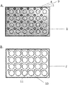
- FIG. 2 depicts a bird's-eye view of the top netwell insert plate (A) and the bottom irrigation plate (B) according to one of the embodiments of the present invention.
- FIG. 3A depicts a side view of the multiwell plate system according to one of the embodiments of the present invention.
- FIG. 3B depicts a cross section of the multiwell plate system according to one of the embodiments of the present invention.
- FIG. 4 Arabidopsis in vivo growth and compound testing using the netwell assay.
- Arabidopsis Rosette growth was determined as the Rosette area (y-axis) was measured over time (days after sowing (DAS) at x-axis) of Arabidopsis plants grown in the multiwell plate system upon treatment with a Stroby® solution containing 10-9 M Kresoxim-methyl (“Stroby”), a cytokinin solution containing 10 ⁇ M 6-Benzylaminopurine (“BAP”), and control water treatment (“water”). Eight plants (or wells) were used per treatment.
- FIG. 5 Arabidopsis in vivo growth 13 DAS
- A, Netwell plate system of the current invention provides a volume to fit about 1.5 g of soil and stable humidity control
- Millicell (Millipore) plate system provides a volume to fit about 0.66 g of soil, resulting in more frequent watering needs and slower plant growth or lower plant yield.
- FIG. 6 Arabidopsis in vivo growth and soil type testing using the netwell assay.
- Arabidopsis Rosette growth was determined as the Rosette area (y-axis) was measured over time (days after sowing (DAS) at x-axis) of Arabidopsis plants grown in the multiwell plate system using different types of soil, and control normal soil. One plate with 24 wells/plants were used per soil type.
- FIG. 7 Arabidopsis in vivo growth and different NAA concentration testing using the netwell assay.
- A for each plate, a different concentration or treatment was applied for each column. The experiment was repeated for at least 4 different plates, each with a different column position for the controls/concentration treatments.
- B Arabidopsis Rosette growth was determined as the Rosette area (y-axis) was measured over time (days after sowing (DAS) at x-axis) of Arabidopsis plants grown in the multiwell plate system using different concentrations of NAA (1, 10, 20, and 100 ⁇ M; 50 ⁇ M was also tested, but left out since similar results were found as for the 100 ⁇ M wells), and control treatment with 0.1% DMSO.
- FIG. 8 Arabidopsis in vivo growth and compound testing using the netwell assay.
- Arabidopsis Rosette growth was determined as the Rosette area (y-axis) was measured over time (days after sowing (DAS) at x-axis) of Arabidopsis plants grown in the multiwell plate system upon treatment with a cis-cinnamic acid-containing (Cis-CA) solution at different concentrations (A), or a Paclobutrazol-containing solution at different concentrations (B), as compared to a control vehicle treatment (“0.1% DMSO”).
- the present invention aims to provide a multiwell plate system which solves one or more of the aforementioned disadvantages of the use of the currently available multiwell plate systems for in vivo plant growth and screening.
- the present invention also aims to provide a method for growing samples, and in particular to perform in vivo compound screening assays, thereby solving one or more of the aforementioned disadvantages for high-throughput agro-chemical screening.
- At least one embodiment of the present invention adopts the following constructions as illustrated in the embodiments described below, some of which are also illustrated by the drawings.
- numerals affixed to respective elements merely exemplify the elements by way of example, with which it is not intended to limit the respective elements.
- this invention is not limited to particular devices and methods or combinations described, since such devices and methods and combinations may, of course, vary. It is also to be understood that the terminology used herein is not intended to be limiting. The present invention will be described with respect to particular embodiments and with reference to certain drawings but the invention is not limited thereto but only by the claims.
- the present invention provides a device and a method allowing to uninterruptedly grow plant tissue for high-throughput in vivo screening assays using a multiwell plate system with a dual well architecture, adapted to obtain reliable stable growth conditions for solid support media.
- the multiwell plate system allows plant tissue growth in granular media, such as soil, protected from light, in large enough volumes to allow robust plant growth, reliable humidity control, and with the possibility of automated, undisturbed addition of nutrient solution or compound treatments without resulting in difficulties in handling or inhomogeneous distribution of the liquid solutions to the samples.
- the present invention provides in a multiwell plate system comprising a top netwell insert plate ( 1 ) and a bottom irrigation plate ( 2 ), mounted onto each other, having a multiplicity of wells, and including a plate body ( 9 ).
- the plate body of the netwell insert plate defines an array of well openings or sample holes ( 3 ), and an arrangement of access holes ( 4 ), as shown in FIG. 1 and FIG. 2 .
- a hollow chamber ( 5 ) is present to house the supportive medium, and is secured in the bottom by a permeable barrier or porous membrane ( 6 ), which has a pore size ranging between 200 ⁇ m and 1000 ⁇ m, to allow support to a tissue sample residing in said supportive medium, particularly a granular medium ( FIG. 3 ).
- a permeable barrier or porous membrane 6
- the term “well” used for said netwell insert plate refers to a combination of a “well opening” or “sample hole” defined in the plate body, and an inwardly connecting “hollow chamber” to constitute the sample support.
- an irrigation channel ( 7 ) Inward from the access holes of the netwell insert plate, an irrigation channel ( 7 ), which is connected with the access hole, connects the access hole further through the bottom of the netwell insert plate, where an open ending ( 8 ) is present, to allow solution added via the access hole to arrive in the irrigation plate well when the plates are mounted onto each other ( FIGS. 1 and 3 ).
- Each of the respective one of the netwell insert plate wells ( 3 ) is accompanied by an adjacent one of the access holes ( 4 ), and therefore each of the hollow chambers also accompanied by an irrigation channel, as shown in FIG. 3B .
- the access hole is not in connection with the well opening, so the access hole is adjacent but separated from the wells by the plate body, wherein “adjacent” is defined as “nearby” “adjoining” the well, but not in connection with the well via the insert top plate, in such a way that the plate surface is built up of an array of well openings which are all in a similar configuration close to an access hole.
- the irrigation plate also comprises a number of wells ( 10 ), corresponding to the number and position of the wells of the netwell insert plate, but with a shape which fits the corresponding hollow chamber of the corresponding netwell insert plate well, in addition to its adjacent irrigation channel ( FIG. 1, 2B, 3 ). This requirement leads to a shape of the irrigation plate wells containing an inlet ( 11 ), as demonstrated also in FIGS. 2B and 3B .
- the hollow chamber with its porous membrane will be housed in a reservoir or well of the irrigation plate ( 10 ), which is in one embodiment filled with liquid solution, added via the access hole and passing the irrigation channel.
- the porous, hydrophilic properties of the membrane will allow the solution to move upwards via capillary forces into the granular medium present in the hollow chamber, as in some embodiments, so as to supply the irrigation solution to the granular medium, and hence to nourish the tissue sample placed in the granular media housing in the hollow chamber.
- the applied terms are further defined as follows.
- the term “mounted” means that to form the multiwell plate system, the top netwell insert plate is placed onto the upper side of the bottom irrigation plate. In one embodiment, the top netwell insert plate is removably mounted onto the irrigation plate. In another embodiment, the top netwell insert plate is mounted onto the irrigation plate, followed by sealing over the edges. This advantageously avoids drying out and inhomogeneous conditions in the samples from different wells, more particular stable humidity control is achieved, thereby providing a screening device to deliver reproducible data as taught herein.
- the “access holes” ( 4 ) extend through the upper surface of the netwell insert plate body and the term refers to providing access to single wells ( 10 ) in the irrigation plate into which also the hollow chamber of the netwell insert plate is positioned when the multiwell plate system is in a mounted position.
- Each of the access holes is preferably adjacent to a netwell insert plate well opening, and connected in fluid communication with a respective one of the irrigation plate wells.
- water, nutrient or treatment solution can be introduced manually through access holes with a conventional liquid handling device, such as a syringe or a pipette, or automatically via robotics, to end in the irrigation plate well.
- the shape and size of the access holes can have larger or smaller diameters, and different center-to-center distances could be used, depending upon the size of the pipette tip to be inserted therein. Of course, other shapes and other dimensions could be varied to suit a customized arrangement, or other standard pipette shapes and lengths that are known to those of skill in the art. Circular access holes are easiest to apply automated handling.
- the center-to-center distance between adjacent ones of the access holes is preferably the same as the center-to-center distance between the wells, which is 1.93 cm in the illustrated embodiment of 24 wells.
- the pairing arrangement of the access holes and the wells allows addition of any solution individually to each well, without cross-contamination of the samples, and without disturbance of the biological samples or removing of any of the plates.
- the pairing arrangement allows the solutions to be different in concentration, amount and compound to test for each individual well selectively.
- Selectively addressing wells would be useful if, for instance, the tissue in one of the wells was generating a strong expression response to an agent, such as increased growth of tissue, increased expression of a polypeptide, added resistance to a selective agent such as a herbicide, or resistance to a plant pathogen.
- an agent such as increased growth of tissue, increased expression of a polypeptide, added resistance to a selective agent such as a herbicide, or resistance to a plant pathogen.
- Other biochemical or biophysical responses could also be assayed in individual wells with the present invention.
- the media from this well could be irrigated and tested more frequently than the other wells.
- more frequent collection and testing of media from that well would provide a stronger statistical correlation.
- An “irrigation channel” ( 7 ) as taught herein is the inwarding volume following the access holes, wherein each of the irrigation channels connects a respective pair of the netwell insert plate wells and access holes in fluid communication, as shown in FIG. 3B .
- Each of the irrigation channels is preferably roughly of similar shape as the access hole, and is separated from the hollow chamber by the netwell insert plate body.
- the irrigation channels end in an opening ( 8 ) in the bottom, where, when mounted onto the irrigation plate, the applied solution in the access hole, will be passed through the irrigation channel to end up in the corresponding irrigation plate well.
- each of the irrigation channels act, along with its respective one of the wells and the access holes, as a reservoir for excess irrigation solution that has not been taken up over the porous membrane in the hollow chamber media.
- the width of each of the irrigation channels is less than the diameter of its respective one of the wells so as to end in an inlet at the bottom of the irrigation plate well.
- the term “hollow chamber” ( 5 ) used herein teaches as the volume following the netwell insert plate well openings, as illustrated in FIG. 1 and FIG. 3B .
- the shape is corresponding to the shape of the netwell insert plate wells, and in order to create an overflow region in the irrigation plate, the height of the hollow chamber is preferably smaller as compared to the sum of the height of the netwell insert plate and the irrigation plate wells, preferably said hollow chamber height is 5%, 10%, 20%, or 30% smaller in height compared to the sum of the height of the netwell insert plate and the irrigation plate wells to allow enough volume for the irrigation solution within the irrigation plate wells.
- the hollow chamber is interchangeably called a “sample holder” as the biological sample is placed herein.
- the hollow chamber is first filled with sample support media, such as granular media, preferably soil. Irrigation of the sample, via capillary forces through the porous membrane and the granular media, is accomplished when the multiwell plate system is mounted and irrigation solution is added via the access hole to reach the irrigation plate wells via the irrigation channel.
- the irrigation plate can be filled with irrigation solution prior to mounting of the netwell insert plate onto the irrigation plate, which will also allow the tissue that is present in the hollow chamber to be irrigated after mounting the netwell insert plate onto the filled irrigation plate.
- the volume of the hollow chamber can vary according to the type of samples and media, as well as to the type and size of the experiment.
- the exemplified 24 well system provides a non-limiting example of an appropriate hollow chamber volume to fill with approximately 1.5 g of soil, which is at least twice the amount of the amount of soil that can be filled in the currently existing systems (e.g. 0.66 g in the 24 well Millicell plates from Millipore), thereby allowing a more reliable and robust humidity control requiring lower irrigation frequencies as compared to other plate devices, and providing more suitable growth environment (see Example 3 and FIG. 5 ).
- porous membrane can be used interchangeably and refers to a barrier that is permeable to liquid solutions but not particulate materials, such as granular media, over the rated pore size.
- Porous membranes may be formed in a variety of shapes, and is within each well, where it holds the granular media in its interstices, allowing contact between the media and the solution applied via the access holes.
- Each porous membrane is constructed of a (synthetic) polymer such as a plastic (e.g. polypropylene, polyethylene, or polystyrene).
- the porous membrane is a hydrophilic mesh, which means consisting of a hydrophilic material appearing as a net with spaces in it, made from wire, plastic, or thread, wherein said mesh is made from polystyrene in a particular embodiment.
- the polystyrene material is porous and hydrophilic to promote the attraction and retention of the media within its interstices.
- the hydrophilic material of the mesh is not polyester.
- the porous membrane is hydrophilic, and not polycarbonate.
- the hydrophilicity of the porous membrane can be permanent or temporary depending upon the processes by which it is applied, or whether the material is inherently hydrophilic.
- Alternative materials with porous structures could be used and a surfactant could be applied to materials not naturally hydrophilic to make them hydrophilic.
- the material is produced by sintering and allows solutions to pass upwards through the pores by capillary action.
- the range of the pore size of said porous membrane surprisingly determined whether the system of watering via the irrigation channel would function to obtain a robust humidity.
- Millicell Millipore system provides membranes with a small pore size (up to 8 ⁇ m for a 24 well plate), which are capable of housing granular media inside the hollow chamber, the desired effect of capillarity of a watering solution added via the access hole into a granular medium such as soil is less effective using this system, i.e. when a porous membrane with a small pore was used (Example 3).
- the invention describes a porous membrane with an average pore size in a range of 200 to 1000 micrometers, wherein the exact pore size and the allowable range is defined by the capability of the pores to retain a certain type of granular media, such as soil, and so that the pores still allow liquid solutions, such as water, to be passing through the pores via capillary forces.
- the pore size is in a range of about 250 to 900 ⁇ m, of about 300 to 800 ⁇ m, of about 350 to 700 ⁇ m, of about 400 to 600 ⁇ m, and in a preferred embodiment, the pore size is between about 400 and 500 ⁇ m, for use of granular medium such as soil.
- the pore size can be adapted within said ranges depending on the type of granular medium, as the “grain” or “particle” size of the medium will define the allowable pore size range in which the medium will be retained, and liquid solution is passing through.
- granular medium refers to a material showing a granulated structure, composed of granules, made of or appearing to be made of small pieces or granules.
- a granular material is a conglomeration of discrete solid, macroscopic particles large enough that they are not subject to thermal motion fluctuations.
- Some examples of granular materials are coal, sand, rice, coffee, and soil.
- granular medium the present invention teaches hence such defined media, with in particular, examples of media to grow plant tissue, such as sand, perlite, vermiculite, and all classes of granular soil.
- Soil is defined as the top layer of the earth's surface in which plants can grow, consisting of rock and mineral particles, mixed with decayed organic matter and having the capability of retaining water.
- a granular soil medium hence comprises sediments or other unconsolidated accumulations of finely ground rock particles in addition to minerals.
- Different soil types are distinguished, based on their texture or different sizes of mineral particles. For example, the largest particles, sand, determine aeration and drainage characteristics, while the tiniest, sub-microscopic clay particles, are chemically active, binding with water and plant nutrients. The ratio of these sizes determines soil type, of which there are many classifications: clay, loam, clay-loam, silt-loam, peat, chalky soil, and so on.
- a granular medium is also defined as a mixture of any of those granular media and any of those materials comprised in soil.
- the use of the multiwell plate system is exemplified with reference to FIGS. 1, 2 and 3 .
- the netwell insert plate of the multiwell plate system is positioned on top of the irrigation plate, both including a multiplicity of wells, such as 24 wells that are corresponding in number and size and location.
- the irrigation plate together with the access holes to the irrigation channels may be used as a watering system or it may be used in a screening assay, such as in compound assay studies to supply treatment solution.
- the multiwell plate system is mounted as such that a hollow chamber, secured by a porous membrane in the bottom, extends into only one well of the irrigation plate, with a relative position of the center of each hollow chamber corresponding to the center of each irrigation plate well.
- Each of the netwell insert plate wells has associated therewith an access hole which permits access to an irrigation plate well of the multiwell plate system utilized during a sample assay step.
- the multiwell plate system as described herein provides that said multiwell plate system is made from a combination of at least two different types of material, one material constituting the porous membrane, as described above, and the second material constituting the plate body, wherein said second material is preferably resistant enough to heat to be sterilized in an autoclave for reuse.
- the second material constituting the plate body is made from non-transparent or non-light transmissible material, to protect the irrigation solution and/or sample holder, or plant roots from light.
- the multiwell plate system's non-transparent plate body in particular protects roots, housing media, and irrigation solution from light or UV, which is advantageous when performing experiments over a longer time in non-sterile (in vivo) conditions to avoid growth of algae, fungi, and to maximally mimic the natural environment.
- the term “plate body” refers to the solid material of the multiwell plate system that is annotated as a diagonal pattern in FIG. 3B , and is made of, for example but not limited to, a plastic block that can be machined. Generally, the hardness of the material defines whether it will allow to be machined by computer controlled milling machine, or other automatic machining process, into complex, precision shapes.
- the plate body could be constructed of different materials, such as a polystyrene, polysulphone, polyoxymethylene (POM), epoxy, vinylester or polyester thermosetting plastic, or high or low density polyethylene.
- suitable material include synthetic rubber, such as styrene ethylene butylene styrene (SEBS), or thermoplastic elastomers (TPE), such as styrenic block copolymers (TPE-s), polyolefin blends (TPE-o), elastomeric alloys (TPE-v or TPV), thermoplastic polyurethanes (TPU), thermoplastic copolyester, metals, ceramics, glass, amongst others.
- SEBS styrene ethylene butylene styrene
- TPE thermoplastic elastomers
- TPE-s styrenic block copolymers
- TPE-o polyolefin blends
- TPE-v or TPV elastomeric alloys
- TPU thermoplastic polyurethanes
- thermoplastic copolyester metals, ceramics, glass, amongst others.
- the height of the multiwell plate system plate body ranges between about 10 mm and 100 mm, preferably between about 20 mm and 50 mm, more preferably between about 25 mm and 30 mm, such as for instance about 26.45 mm.
- the plate shape is rectangular, with a length of for instance 127.65 mm for standard well plates.
- the plate body has a flat upper surface through which the access holes and wells are drilled. It should be noted, that although the size of the body is preferably configured for compatibility with preexisting equipment, the dimensions of the body can be varied as desired, allowing easy and sufficient growth of plant tissue from different plants or crops.
- sample biological sample
- tissue sample tissue sample
- the biological sample may be obtained for example, but without limitation, from plant material such as from dicot and monocot plants or plant tissue from for instance Arabidopsis thaliana, Medicago truncatula , corn ( Zea mays ), Brassica sp., alfalfa ( Medicago sativa ), rice ( Oryza sativa ), sorghum ( Sorghum bicolor, Sorghum vulgare ), wheat ( Triticum aestivum ), soybean ( Glycine max ), tobacco ( Nicotiana tabacum, N.
- plant material such as from dicot and monocot plants or plant tissue from for instance Arabidopsis thaliana, Medicago truncatula , corn ( Zea mays ), Brassica sp., alfalfa ( Medicago sativa ), rice ( Oryza sativa ), sorghum ( Sorghum bicolor, Sorghum vulgare ), wheat ( Triticum aestivum
- benthamiana potato ( Solanum tuberosum ), tomato ( Solanum lycopersicum ), cotton ( Gossypium barbadense, Gossypium hirsutum ), sugar beets ( Beta vulgaris ), and sugarcane ( Saccharum spp.), amongst others.
- the number, shape and size of the wells depends on the type of sample applied.
- the multiwell plate system may comprise between 2 and 24 wells.
- said multiwell plate system comprises 6, 12, or 24 wells.
- the number, dimensions and locations of the wells are also tailored to be compatible with preexisting equipment.
- the plate preferably has 24 wells in an array of 4 by 6, or 12 wells in an array of 3 by 4 to be compatible with most liquid handling devices.
- Other well densities could be used such as 6 wells, that are compatible with conventional devices.
- nonstandard well densities could also be used, such as two wells, 3, 4, 5, 7, 8, 9, 10, 11, 13, 14, 15, 16, 17, 18, 19, 20, 21, 22 or 23 wells.
- the number of wells will be limited by such practicalities as the size of the plate body, the type of sample, the capabilities of the equipment using the wells and the required size of the wells themselves, the required liquid solution volume, and so on.
- the multiwell plate system provides that said wells of said netwell insert and/or said irrigation plates have a square, rectangular, rounded rectangular, oval rectangular, squircular, oval or circular circumference.
- the circumference or edge of said wells refers to the shape of the rim of the wells that makes contact with the plate body of the multiwell plate system.
- said shape is rounded rectangular, oval rectangular, oval or circular.
- said irrigating plate wells have in addition to the well shape, an additional inlet, as provided in FIG. 2B , to fit the irrigation channel inserted from the netwell insert plate when both plates are mounted onto each other.
- each of the wells has a standard circular shape for the 24 well plate.
- the 24 well plate has been determined by the inventors to be particularly suitable to the seedling propagation of Arabidopsis seeds/seedlings, over a period of 14 days after sowing, presenting a preferred balance of tissue volume and density of wells.
- the density of the wells used for other plant types can be less or more due to the size of the plant and duration of the experiment/growth phase. For instance but not limiting, the density of the wells for wheat, tomato or maize seedlings will become lower due to a larger size of those type of plants as compared to Arabidopsis plants after growth for a certain number of days.
- the present invention provides in the use of the multiwell plate system according to the present invention for an in vivo screening assay for uninterruptedly growing of plant tissue, wherein said hollow chamber of the netwell insert plate contains a granular medium serving as a solid sample support, such as soil in one particular embodiment.
- the device provided by the present invention allows a person skilled in the art for the first time to immediately perform high-throughput compound screenings in natural substrates such as granular media, and applying more optimal conditions (e.g. roots protected from light, no oxygen deprivation, and stable humidity control) thereby avoiding lengthy in vitro selection procedures including additional risks of identifying false positives.
- An in vivo screening assay wherein plant samples are growing supported by granular media and nourished with nutrition solution applied via the access holes, in addition allows to identify new compounds that affect plant growth and development.
- a treatment solution is applied, in the same manner as the nutrition or watering solution is applied, the effect of the treatment can be monitored over time, in several ways, such as by imaging analysis.
- a “compound” or “test compound” is defined herein as any chemical or biological compound, including simple or complex organic and inorganic molecules, small molecules (e.g. growth regulators or hormones), peptides, peptidomimetics, proteins, antibodies, carbohydrates, nucleic acids or derivatives thereof, biologicals, bacterial isolates, all derived synthetically or from natural resources.
- treatment or “treating” or “to treat” can be used interchangeably and is taught in the present invention as application of a “treatment solution” to a sample or well, in which the treatment solution contains said test compound, with the aim to test the impact of the treatment solution on the progression of plant sample development or growth in a certain condition.
- the present invention provides in a netwell assay screening method for producing a compound, comprising several steps, in one embodiment initiated by inserting a granular medium, preferably soil, in the hollow chamber of said netwell insert plate wells; followed by bringing in of the sample, preferably plant tissue, seedlings or seed, in said granular medium of each well; mounting the netwell insert plate onto the irrigation plate; addition of irrigation solution via the access hole in said irrigation channel; followed (optionally) by sealing of the multiwell plate system over the edges; incubation of the plant tissue until treatment is desired, including the necessary provision of watering or nutrient solution on a regular basis; treatment with test-compound-containing solution via the access hole without disturbance of the sample, manually or in some embodiments automatically, using robotics.
- a netwell assay screening method for producing a compound comprising several steps, in one embodiment initiated by inserting a granular medium, preferably soil, in the hollow chamber of said netwell insert plate wells; followed by bringing in of the sample, preferably plant tissue, seedling
- a control sample is defined as a reference standard sample, meaning that the same tissue is used, but treated with an irrigation solution that does not contain the testing compound, or that contain an inactivated test compound or vehicle control.
- a control sample could also be a sample well which receives the same treatment as the samples or wells of interest, but differs from the other samples in genetic background, species, type, or age.
- Another option is that the control sample uses another type of granular medium, such as for instance a rich or poor type of soil.
- said method is applied for use in a compound screening assay wherein said screening assay aims to identify compounds for improved plant characteristics or more particular improved plant yield, which can be evaluated for instance as exemplified below, but also in different manners, and by different phenotyping analytical methods, depending on the goal of the assay.
- a person skilled in the art is supposed to define a suitable evaluation procedure to define when a compound can be identified as being a candidate for improving plant characteristics, or plant yield, based on the result of the screening assay.
- An improved plant characteristic or plant performance is described herein as a plant breeding being improved as compared to a wild-type variety of the plant. So preferably, improved is determined relative to the characteristics in a control plant, or a control treatment. Examples of different plant characteristics improved by the identified compound or the resulting improved plant performance include increased root growth, increased seedling vigor, increased or decreased branching, resistance to oxygen stress/hypoxia; tolerance to abiotic stresses in general, and more specific to drought conditions or heat; improved water use efficiency; lower stomal density and/or index; increased or decreased hormone sensitivity, resistance to biotic stress, amongst others.
- the multiwell plate system when nutrient supply is performed automatically, the multiwell plate system is loaded on the liquid handling device of choice to replenish the irrigation solution via the access hole in hollow chamber.
- the liquid handling device extends each pipette tip into a respective one of the access holes, providing the necessary amount of solution through the irrigation channel.
- the irrigation solution volume is supplied as often as needed by repeating the above process.
- an automated pipetting head or robotic liquid handler
- the tips of the robot are configured to deliver irrigation solution or treatment solution to a plurality of wells on multiple multiwell plate systems at once.
- a robotic liquid handler is operated using a software program to control deployment of its pipetting tips in such a way as to minimize cross-contamination between the wells.
- FIG. 1 illustrates the Multiwell Plate System.
- the multiwell plate system comprises the upper netwell insert plate ( 1 ) and the bottom irrigation plate ( 2 ), which can be mounted together to obtain a closed in vivo growth and screening system.
- the upper netwell insert plate contains 24 wells ( 3 ), each well accompanied by a corresponding access hole ( 4 ), which allows the addition of a solution to the wells. When a certain amount of solution is added via the access hole ( 4 ), it will pass through the irrigation channel ( 7 ) to the bottom of the netwell insert plate, which is an opening ( 8 ) being in contact with in the corresponding irrigation plate well ( 10 ).
- FIG. 2 illustrates the Upper Netwell Insert Plate (A) and Bottom Irrigation Plate (B) of the Multiwell Plate System.
- the upper netwell insert plate top view depicted in FIG. 2A demonstrates that all individual well openings ( 3 ) are accompanied by an access hole ( 4 ), and equally distributed among the plate surface, to allow maximum space for each sample.
- the access holes are not connected to the individual well openings in the upper netwell insert plate, but separated by the plate body ( 9 ).
- the bottom irrigation plate top view as depicted in FIG. 2B shows that each well ( 10 ) is shaped in such a manner that an inlet ( 11 ) is present to receive the solution from the accompanying access hole/irrigation channel. In this way, in the bottom irrigation plate, each of the wells is in connection with the separate inlet area, to provide a connection between the irrigation channel and the receiving hollow chamber of the corresponding netwell insert plate well.
- FIG. 3A Shows a Side View of the Multiwell Plate System.
- the upper netwell insert plate ( 1 ) is only visible as a thin bar (dashed grey fill), since most of the insert plate is mounted and inside of the irrigation plate ( 2 ).
- the irrigation plate is visible as the bottom bar (equal grey fill), and is designed to allow mounting of the insert plate, and retaining enough space in the bottom of the wells to receive solutions to be provided to each of the insert well opening through capillary forces through the porous membrane into the granular medium of the hollow chambers of the netwell insert plate wells.
- FIG. 3B Shows a Cross Section of the Multiwell Plate System.
- the insert plate well opening ( 3 ) ends inwardly as a hollow chamber ( 5 ) in which the granular medium will be housed, and which is secured in the bottom by a porous membrane ( 6 ) consisting of, for instance, hydrophilic mesh.
- the access hole ( 4 ) accompanying the insert plate well opening allows solution to be added to the samples as the solution added to the access hole will pass through the irrigation channel ( 7 ) of the netwell insert plate, to end up in the bottom opening of said insert plate ( 8 ).
- the wells ( 10 ) of the irrigation plate ( 2 ) are corresponding in size and shape to fit the insert plate hollow chamber, with in addition an inlet ( 11 ), to fit the irrigation channel of the netwell insert plate and receive the solution added via the access hole, as a fluid communication is maintained between the irrigation channel and the hollow chamber via said irrigation plate wells when the plates are mounted.
- the plate body ( 9 ) consisting for instance of plastic material, is annotated as a diagonal pattern, with lines going right upward for the irrigation plate body, and going left upward for the insert well plate body.
- the dashed vertical lines are not part of a feature, but only illustrating the center of the wells and irrigation channel.
- plants were grown in soil inside a 24 well netwell insert plate comprising a polystyrene porous membrane with a pore size of about 420 ⁇ m, which is positioned into a 24 well irrigation plate ( FIG. 1, 2 ).
- the netwell insert plate was filled with fine potting soil, or optionally with soil mixed with sand (ratio 3:1). During this process the soil (or soil with sand) was compressed two times (or optionally three times for soil/sand) by applying a light pressure onto the individual netwells.
- a “humidity control” soil sample was taken for determination of the initial soil water humidity (see later).
- one mL of water was added to each of the wells of the irrigation plates.
- the netwell insert plates were positioned inside the irrigation plates and the mounted plates were sealed with (plastic) tape surrounding the edges, to prevent excessive water evaporation from the boundary wells as compared to the center wells of the 24 well plate. This was a crucial step to avoid growth differences between plants in boundary and center wells, and to obtain reproducible results.
- the weight of the combined insert and irrigation plates was recorded.
- the plants received a (chemical) treatment. Therefore, 0.5 (optionally 0.8 mL for soil with sand) of a (chemical-containing) solution was added to each of the wells via the corresponding access holes. Each plant sample receives the supplied (same) amount of (chemical) solution.
- the plants were again irrigated with water to maintain a soil water humidity of 3.5 (or optionally 0.95 for soil with sand) (see below).
- the growth of Arabidopsis plants was typically followed for about 15 days, during which image analysis procedures were used to follow the growth of the individual plant samples over time and to quantify the growth response of these plants in response to the specific (chemical) treatments.
- the initial soil water humidity was determined by first drying the “humidity control” soil sample in an oven at 60 degrees Celsius, to obtain the “dry weight”. Next, taking into account the weight of the empty irrigation plates, the empty netwell insert plates, and the current weight of the combined insert and irrigation plates, water was added to each of the wells to reach a “soil water humidity” of “3.5 gram water per gram of dry soil” or “3.5” (optionally, when soil with sand was used: “0.95 gram water per gram of dry soil (with sand)” was used as initial soil water humidity value). Water was added into the irrigation plate wells through the access holes present in the corresponding netwell insert plate wells using a repetition pipet.
- each well of the irrigation plate received the same amount of water, rounded to 100 ⁇ L.
- the water, added to the wells in the irrigation plates, is taken up by the soil present in the hollow chambers of the netwell insert plate wells, through the mesh by capillary forces ( FIG. 3B ).
- This irrigation was repeated on a daily basis to prevent excessive drying of the soil in the wells.
- This watering regime is suitable for frequently used Arabidopsis growth conditions, but can be altered and further optimized when a plant drought-stress response is the desired testing regime.
- the different treatments comprise a) a Stroby® solution containing 10 ⁇ M Kresoxim-methyl ( FIG. 4 , “Stroby”), b) a cytokinin solution containing 10 ⁇ M 6-Benzylaminopurine ( FIG. 4 , “BAP”), and c) water as a control treatment ( FIG. 4 , “water”). Growth of individual plants was followed over time by daily imaging between 4-16 DAS. Projected rosette sizes were measured using image analysis procedures. Average rosette areas were calculated over time per treatment ( FIG. 4 ). Treatment with the Stroby® solution showed a plant growth enhancing effect, whereas the cytokinin application resulted in shoot growth inhibition ( FIG. 4 ).
- Millipore for in vitro cell culture was tested for its use in in vivo plant screening, starting with water irrigation.
- the Millicell 24 cell culture insert plate system (PSET010R5), with a pore size 8 ⁇ m, was assembled, and watering solution was added via the access port of the system.
- the hollow chamber volume for soil was determined in the Millicell 24 cell culture insert plate to fit about 0.66 g of soil, whereas in the netwell plate system of the invention, the hollow chamber fitted about 1.50 g of soil, which is about double the amount for the same amount of wells in the same plate size.
- the advantage of the system of the current invention is that the bigger pore size of the membrane and the larger volume of medium housing the hollow chamber surprisingly provided more optimal growth conditions, most likely due to more stable humidity control and less frequent need for watering, resulting in larger plantlets, and hence more robust and reliable results ( FIG. 5 ).
- Plants were grown as described in the above Netwell assay method. No treatment was added to the watering scheme, but a series of 4 plates, each with 24 Arabidopsis seedlings and each with a different type of soil granular housing medium were compared.
- the different soil types comprise soil with fertilizer, propagation soil, poor soil, and normal soil as a control ( FIG. 6 ). Growth of individual plants was followed over time by daily imaging between 4-14 DAS. Projected rosette sizes were measured using image analysis procedures. Average rosette areas were calculated over time per soil type ( FIG. 6 ).
- the soil containing plant fertilizer showed a plant growth enhancing effect as compared to the normal control soil, whereas the poor soil resulted in a significant reduced growth as compared to the normal control soil ( FIG. 6 ), and finally the propagation soil and normal soil did not demonstrate significant differences in plant growth, as expected.
- the different soil types demonstrate also plate-to-plate robustness of the system to quantify between different plates.
- the treatment comprises a 1-Naphthaleneacetic acid (NAA) hormone treatment solution at different concentrations, as indicated in FIG. 7 .
- NAA 1-Naphthaleneacetic acid
- FIG. 7A comprising of control samples in different columns.
- FIG. 7B The average of all plates per concentration for each timepoint was calculated, and is shown in FIG. 7B for a concentration of 100 ⁇ M, 20 ⁇ M, 10 ⁇ M, and 1 ⁇ M, as compared to the negative control, which is DMSO (vehicle control).
- DMSO vehicle control
- the treatment provided in FIG. 8A comprises an irrigation solution containing different concentrations of cis-cinnamic acid (cis-CA) and 0.1% DMSO as a control treatment.
- cis-CA cis-cinnamic acid
- DMSO DMSO
- the treatment provided in FIG. 8B comprises an irrigation solution containing different concentrations of Paclobutrazol and 0.1% DMSO as a control treatment.
- Treatment with the Paclobutrazol-containing solution showed a plant growth retarding effect, with a dose response measured within the same plate for different concentrations at 10, 20, and 100 ⁇ M of Paclobutrazol treatment versus the DMSO controls ( FIG. 8B ).
Abstract
Description
-
- (a) inserting a granular medium, preferably comprising soil, in the hollow chamber of said netwell insert plate wells;
- (b) bringing in of the sample, preferably a plant tissue, seedlings or seed, in said granular medium of each well;
- (c) mounting the netwell insert plate onto the irrigation plate;
- (d) addition of irrigation solution via the access hole in said irrigation channel; optionally followed by sealing of the multiwell plate system over the edges
- (e) treatment with test-compound-containing solution via the access hole without disturbance of the sample manually, or automatically using robotics.
- (f) retaining the necessary soil humidity level by replenishing with said irrigation solution on frequent basis
- (g) monitoring of compound treatment via evaluation of the sample in comparison to control sample
Claims (15)
Applications Claiming Priority (4)
| Application Number | Priority Date | Filing Date | Title |
|---|---|---|---|
| GB1614116 | 2016-08-18 | ||
| GB1614116.0 | 2016-08-18 | ||
| GBGB1614116.0A GB201614116D0 (en) | 2016-08-18 | 2016-08-18 | Netwell assay plate system |
| PCT/EP2017/070874 WO2018033603A1 (en) | 2016-08-18 | 2017-08-17 | Netwell assay plate system |
Publications (2)
| Publication Number | Publication Date |
|---|---|
| US20190184392A1 US20190184392A1 (en) | 2019-06-20 |
| US11213815B2 true US11213815B2 (en) | 2022-01-04 |
Family
ID=57045622
Family Applications (1)
| Application Number | Title | Priority Date | Filing Date |
|---|---|---|---|
| US16/325,838 Active 2038-09-05 US11213815B2 (en) | 2016-08-18 | 2017-08-17 | Netwell assay plate system |
Country Status (5)
| Country | Link |
|---|---|
| US (1) | US11213815B2 (en) |
| EP (1) | EP3500365A1 (en) |
| CA (1) | CA3033103C (en) |
| GB (1) | GB201614116D0 (en) |
| WO (1) | WO2018033603A1 (en) |
Citations (15)
| Publication number | Priority date | Publication date | Assignee | Title |
|---|---|---|---|---|
| US5801055A (en) | 1997-09-10 | 1998-09-01 | Becton Dickinson And Company | Multi-well culture dish assembly |
| US5837198A (en) | 1995-12-28 | 1998-11-17 | Aloka Co., Ltd. | Physiological tissue treatment apparatus |
| WO1999019067A1 (en) | 1997-10-10 | 1999-04-22 | Biosepra, Inc. | Aligned multiwell multiplate stack and method for processing biological/chemical samples using the same |
| US5972694A (en) | 1997-02-11 | 1999-10-26 | Mathus; Gregory | Multi-well plate |
| US20020189374A1 (en) | 2001-06-14 | 2002-12-19 | Desilets Kenneth | Multiwell test apparatus |
| US20030026738A1 (en) | 2001-05-30 | 2003-02-06 | Biolex, Inc. | Plate and method for high throughput screening |
| US20040087005A1 (en) | 2002-08-30 | 2004-05-06 | Henderson Douglas P. | Multi-well device |
| US20050136506A1 (en) | 2003-12-23 | 2005-06-23 | Lakshmi Kamath | Cell motility assay |
| US7135148B2 (en) | 2001-06-14 | 2006-11-14 | Millipore Corporation | Access holes for a multiwell filter plate for multiwell test apparatus |
| US20060286003A1 (en) | 2005-06-16 | 2006-12-21 | Desilets Kenneth G | Multi-well filter plate with shifted wells and U-bottom receiver plate |
| US7968061B2 (en) | 2004-10-18 | 2011-06-28 | Becton, Dickinson And Company | Microplate with dialysis membrane |
| US8178058B2 (en) | 2007-01-31 | 2012-05-15 | Emd Millipore Corporation | High throughput cell-based assays, methods of use and kits |
| US20130210131A1 (en) | 2012-02-10 | 2013-08-15 | Applied Biophysics, Inc. | Filter device for facilitating characterizing behavior of cells |
| WO2014064542A2 (en) | 2012-10-01 | 2014-05-01 | University Of Oslo | Micro-scale liquid-liquid-liquid extraction |
| US20140273070A1 (en) | 2013-03-15 | 2014-09-18 | Matthew Hale | Aspiration-free well plate apparatus and methods |
-
2016
- 2016-08-18 GB GBGB1614116.0A patent/GB201614116D0/en not_active Ceased
-
2017
- 2017-08-17 EP EP17752402.2A patent/EP3500365A1/en active Pending
- 2017-08-17 CA CA3033103A patent/CA3033103C/en active Active
- 2017-08-17 WO PCT/EP2017/070874 patent/WO2018033603A1/en unknown
- 2017-08-17 US US16/325,838 patent/US11213815B2/en active Active
Patent Citations (16)
| Publication number | Priority date | Publication date | Assignee | Title |
|---|---|---|---|---|
| US5837198A (en) | 1995-12-28 | 1998-11-17 | Aloka Co., Ltd. | Physiological tissue treatment apparatus |
| US5972694A (en) | 1997-02-11 | 1999-10-26 | Mathus; Gregory | Multi-well plate |
| US5801055A (en) | 1997-09-10 | 1998-09-01 | Becton Dickinson And Company | Multi-well culture dish assembly |
| WO1999019067A1 (en) | 1997-10-10 | 1999-04-22 | Biosepra, Inc. | Aligned multiwell multiplate stack and method for processing biological/chemical samples using the same |
| US20080096272A1 (en) | 2001-05-30 | 2008-04-24 | Biolex Therapeutics, Inc. | Plate and method for high throughput screening |
| US20030026738A1 (en) | 2001-05-30 | 2003-02-06 | Biolex, Inc. | Plate and method for high throughput screening |
| US7135148B2 (en) | 2001-06-14 | 2006-11-14 | Millipore Corporation | Access holes for a multiwell filter plate for multiwell test apparatus |
| US20020189374A1 (en) | 2001-06-14 | 2002-12-19 | Desilets Kenneth | Multiwell test apparatus |
| US20040087005A1 (en) | 2002-08-30 | 2004-05-06 | Henderson Douglas P. | Multi-well device |
| US20050136506A1 (en) | 2003-12-23 | 2005-06-23 | Lakshmi Kamath | Cell motility assay |
| US7968061B2 (en) | 2004-10-18 | 2011-06-28 | Becton, Dickinson And Company | Microplate with dialysis membrane |
| US20060286003A1 (en) | 2005-06-16 | 2006-12-21 | Desilets Kenneth G | Multi-well filter plate with shifted wells and U-bottom receiver plate |
| US8178058B2 (en) | 2007-01-31 | 2012-05-15 | Emd Millipore Corporation | High throughput cell-based assays, methods of use and kits |
| US20130210131A1 (en) | 2012-02-10 | 2013-08-15 | Applied Biophysics, Inc. | Filter device for facilitating characterizing behavior of cells |
| WO2014064542A2 (en) | 2012-10-01 | 2014-05-01 | University Of Oslo | Micro-scale liquid-liquid-liquid extraction |
| US20140273070A1 (en) | 2013-03-15 | 2014-09-18 | Matthew Hale | Aspiration-free well plate apparatus and methods |
Non-Patent Citations (4)
| Title |
|---|
| GB Intellectual Property Office Search Report, Application No. GB1614116.0, dated Dec. 22, 2016, 6 pages. |
| Millipore, Multiwell Solutions for Discovery Research and Sample Prep. Fisher Scientific, Multiwell Product Guide, 2008 www.millipore.com/multiscreen, 44 pages. |
| PCT International Search Report and Written Opinion, Application No. PCT/EP2017/070874, dated Nov. 6, 2017, 12 pages. |
| Pelco Prep-Eze, Rectangular Wellplate Inserts—Instructions, Technical Notes, Ted Pella. Inc., https://www.tedpella.com/technote_html/36168_36170_36172.pdf, Accessed 2019. 2 pages. |
Also Published As
| Publication number | Publication date |
|---|---|
| EP3500365A1 (en) | 2019-06-26 |
| GB201614116D0 (en) | 2016-10-05 |
| WO2018033603A1 (en) | 2018-02-22 |
| US20190184392A1 (en) | 2019-06-20 |
| CA3033103A1 (en) | 2018-02-22 |
| CA3033103C (en) | 2023-09-12 |
Similar Documents
| Publication | Publication Date | Title |
|---|---|---|
| ES2261669T3 (en) | HIGH PERFORMANCE SCREEN AND METHOD. | |
| EP1127482B1 (en) | Apparatus for culturing plantlets and process for culturing plantlets by using said apparatus | |
| AU2002303881A1 (en) | Plate and method for high throughput screening | |
| Huttner et al. | An improved, simple, hydroponic method for growing Arabidopsis thaliana | |
| US11213815B2 (en) | Netwell assay plate system | |
| Peña-Valdivia et al. | Anatomical root variations in response to water deficit: wild and domesticated common bean (Phaseolus vulgaris L) | |
| CN205756178U (en) | A kind of high flux screening allelopathic Rice Germplasm Resources device | |
| Pingault et al. | Enhancing phenotyping and molecular analysis of plant root system using ultrasound aeroponic technology | |
| CN201733690U (en) | Device for in situ screening and cultivation of transgenosis arabidopsis thaliana sprouts | |
| CN105900822A (en) | Device and method for screening allelopathic rice germplasm resources with high throughput | |
| AU2003236241A1 (en) | Plant transformation system | |
| CN101904294B (en) | Device for screening and culturing of transgenic arabidopsis seedlings in situ and application thereof | |
| Clark et al. | Protocol: An improved high-throughput method for generating tissue samples in 96-well format for plant genotyping (Ice-Cap 2.0) | |
| US20030097789A1 (en) | Hydroponic growing device adapted for the growing and scientific study of arabidopsis thaliana | |
| CN105794622A (en) | Plant water culture method and special device thereof | |
| CN108513882B (en) | Method for field herbaceous plant environment control test | |
| CN205584987U (en) | Plant water -cultivation device | |
| JP7093999B2 (en) | Container for high-throughput testing using plants | |
| CN209628301U (en) | A kind of plant water-cultivation device of based on PCR plate | |
| Anderson et al. | Plant Roots-From Cells to Systems: Proceedings of the 14th Long Ashton International Symposium Plant Roots—From Cells to Systems, Held in Bristol, UK, 13–15 September 1995 | |
| Griffing et al. | Hydroponic Systems for Arabidopsis Extended to Crop Plants | |
| PL228068B1 (en) | Semi-hydroponic system for conducting the growth of monocotyledonous plants, preferably the grain crops and method for conducting the growth of the plants of this kind |
Legal Events
| Date | Code | Title | Description |
|---|---|---|---|
| AS | Assignment |
Owner name: VIB VZW, BELGIUM Free format text: ASSIGNMENT OF ASSIGNORS INTEREST;ASSIGNORS:INZE, DIRK GUSTAAF;DHONDT, STIJN;SIGNING DATES FROM 20190206 TO 20190207;REEL/FRAME:048344/0237 Owner name: UNIVERSITEIT GENT, BELGIUM Free format text: ASSIGNMENT OF ASSIGNORS INTEREST;ASSIGNORS:INZE, DIRK GUSTAAF;DHONDT, STIJN;SIGNING DATES FROM 20190206 TO 20190207;REEL/FRAME:048344/0237 |
|
| FEPP | Fee payment procedure |
Free format text: ENTITY STATUS SET TO UNDISCOUNTED (ORIGINAL EVENT CODE: BIG.); ENTITY STATUS OF PATENT OWNER: SMALL ENTITY |
|
| FEPP | Fee payment procedure |
Free format text: ENTITY STATUS SET TO SMALL (ORIGINAL EVENT CODE: SMAL); ENTITY STATUS OF PATENT OWNER: SMALL ENTITY |
|
| STPP | Information on status: patent application and granting procedure in general |
Free format text: APPLICATION DISPATCHED FROM PREEXAM, NOT YET DOCKETED |
|
| STPP | Information on status: patent application and granting procedure in general |
Free format text: DOCKETED NEW CASE - READY FOR EXAMINATION |
|
| STPP | Information on status: patent application and granting procedure in general |
Free format text: NON FINAL ACTION MAILED |
|
| STPP | Information on status: patent application and granting procedure in general |
Free format text: RESPONSE TO NON-FINAL OFFICE ACTION ENTERED AND FORWARDED TO EXAMINER |
|
| STPP | Information on status: patent application and granting procedure in general |
Free format text: NOTICE OF ALLOWANCE MAILED -- APPLICATION RECEIVED IN OFFICE OF PUBLICATIONS |
|
| STPP | Information on status: patent application and granting procedure in general |
Free format text: PUBLICATIONS -- ISSUE FEE PAYMENT RECEIVED |
|
| STPP | Information on status: patent application and granting procedure in general |
Free format text: PUBLICATIONS -- ISSUE FEE PAYMENT VERIFIED |
|
| STCF | Information on status: patent grant |
Free format text: PATENTED CASE |