US11213259B2 - X-ray reduction system - Google Patents
X-ray reduction system Download PDFInfo
- Publication number
- US11213259B2 US11213259B2 US16/885,373 US202016885373A US11213259B2 US 11213259 B2 US11213259 B2 US 11213259B2 US 202016885373 A US202016885373 A US 202016885373A US 11213259 B2 US11213259 B2 US 11213259B2
- Authority
- US
- United States
- Prior art keywords
- roi
- shape
- location
- displaying
- collimator
- Prior art date
- Legal status (The legal status is an assumption and is not a legal conclusion. Google has not performed a legal analysis and makes no representation as to the accuracy of the status listed.)
- Active
Links
- 230000009467 reduction Effects 0.000 title description 3
- 230000005855 radiation Effects 0.000 claims abstract description 93
- 238000003384 imaging method Methods 0.000 claims abstract description 32
- 230000033001 locomotion Effects 0.000 claims description 70
- 238000000034 method Methods 0.000 claims description 48
- 210000000056 organ Anatomy 0.000 claims description 33
- 238000010079 rubber tapping Methods 0.000 claims description 26
- 238000012545 processing Methods 0.000 claims description 22
- 230000008878 coupling Effects 0.000 description 42
- 238000010168 coupling process Methods 0.000 description 42
- 238000005859 coupling reaction Methods 0.000 description 42
- 230000007246 mechanism Effects 0.000 description 25
- 238000001914 filtration Methods 0.000 description 12
- 230000002829 reductive effect Effects 0.000 description 10
- 238000009826 distribution Methods 0.000 description 9
- 239000000463 material Substances 0.000 description 8
- 238000013461 design Methods 0.000 description 7
- 230000008859 change Effects 0.000 description 6
- 230000000694 effects Effects 0.000 description 6
- 238000005516 engineering process Methods 0.000 description 6
- 238000004891 communication Methods 0.000 description 5
- 230000008569 process Effects 0.000 description 5
- 239000007787 solid Substances 0.000 description 5
- 238000012937 correction Methods 0.000 description 4
- 230000035515 penetration Effects 0.000 description 4
- 230000000903 blocking effect Effects 0.000 description 3
- 230000006870 function Effects 0.000 description 3
- 239000003292 glue Substances 0.000 description 3
- 238000003702 image correction Methods 0.000 description 3
- 230000003595 spectral effect Effects 0.000 description 3
- 238000003466 welding Methods 0.000 description 3
- RYGMFSIKBFXOCR-UHFFFAOYSA-N Copper Chemical compound [Cu] RYGMFSIKBFXOCR-UHFFFAOYSA-N 0.000 description 2
- 230000005540 biological transmission Effects 0.000 description 2
- 238000012512 characterization method Methods 0.000 description 2
- 230000000295 complement effect Effects 0.000 description 2
- 229910052802 copper Inorganic materials 0.000 description 2
- 239000010949 copper Substances 0.000 description 2
- 238000010586 diagram Methods 0.000 description 2
- 230000009977 dual effect Effects 0.000 description 2
- 238000010191 image analysis Methods 0.000 description 2
- 230000002452 interceptive effect Effects 0.000 description 2
- 238000004519 manufacturing process Methods 0.000 description 2
- 238000010606 normalization Methods 0.000 description 2
- 238000005457 optimization Methods 0.000 description 2
- 230000002123 temporal effect Effects 0.000 description 2
- 238000002083 X-ray spectrum Methods 0.000 description 1
- 238000002835 absorbance Methods 0.000 description 1
- 239000011358 absorbing material Substances 0.000 description 1
- 238000010521 absorption reaction Methods 0.000 description 1
- 230000009471 action Effects 0.000 description 1
- 230000004913 activation Effects 0.000 description 1
- 239000000654 additive Substances 0.000 description 1
- 230000000996 additive effect Effects 0.000 description 1
- XAGFODPZIPBFFR-UHFFFAOYSA-N aluminium Chemical compound [Al] XAGFODPZIPBFFR-UHFFFAOYSA-N 0.000 description 1
- 229910052782 aluminium Inorganic materials 0.000 description 1
- 229910021417 amorphous silicon Inorganic materials 0.000 description 1
- 238000004364 calculation method Methods 0.000 description 1
- 230000001419 dependent effect Effects 0.000 description 1
- 238000001514 detection method Methods 0.000 description 1
- 238000006073 displacement reaction Methods 0.000 description 1
- 239000012636 effector Substances 0.000 description 1
- 230000000670 limiting effect Effects 0.000 description 1
- 230000000873 masking effect Effects 0.000 description 1
- 230000013011 mating Effects 0.000 description 1
- 239000011159 matrix material Substances 0.000 description 1
- 238000005259 measurement Methods 0.000 description 1
- 230000003287 optical effect Effects 0.000 description 1
- 230000037361 pathway Effects 0.000 description 1
- 230000000149 penetrating effect Effects 0.000 description 1
- 238000003825 pressing Methods 0.000 description 1
- 239000012857 radioactive material Substances 0.000 description 1
- 238000002601 radiography Methods 0.000 description 1
- 230000035945 sensitivity Effects 0.000 description 1
- 238000001228 spectrum Methods 0.000 description 1
- 230000003068 static effect Effects 0.000 description 1
- 230000001360 synchronised effect Effects 0.000 description 1
- 230000007704 transition Effects 0.000 description 1
- 238000004846 x-ray emission Methods 0.000 description 1
Images


Classifications
-
- A—HUMAN NECESSITIES
- A61—MEDICAL OR VETERINARY SCIENCE; HYGIENE
- A61B—DIAGNOSIS; SURGERY; IDENTIFICATION
- A61B6/00—Apparatus or devices for radiation diagnosis; Apparatus or devices for radiation diagnosis combined with radiation therapy equipment
- A61B6/06—Diaphragms
-
- A—HUMAN NECESSITIES
- A61—MEDICAL OR VETERINARY SCIENCE; HYGIENE
- A61B—DIAGNOSIS; SURGERY; IDENTIFICATION
- A61B6/00—Apparatus or devices for radiation diagnosis; Apparatus or devices for radiation diagnosis combined with radiation therapy equipment
- A61B6/10—Safety means specially adapted therefor
- A61B6/107—Protection against radiation, e.g. shielding
-
- A—HUMAN NECESSITIES
- A61—MEDICAL OR VETERINARY SCIENCE; HYGIENE
- A61B—DIAGNOSIS; SURGERY; IDENTIFICATION
- A61B6/00—Apparatus or devices for radiation diagnosis; Apparatus or devices for radiation diagnosis combined with radiation therapy equipment
- A61B6/40—Arrangements for generating radiation specially adapted for radiation diagnosis
- A61B6/4035—Arrangements for generating radiation specially adapted for radiation diagnosis the source being combined with a filter or grating
-
- A—HUMAN NECESSITIES
- A61—MEDICAL OR VETERINARY SCIENCE; HYGIENE
- A61B—DIAGNOSIS; SURGERY; IDENTIFICATION
- A61B6/00—Apparatus or devices for radiation diagnosis; Apparatus or devices for radiation diagnosis combined with radiation therapy equipment
- A61B6/44—Constructional features of apparatus for radiation diagnosis
- A61B6/4405—Constructional features of apparatus for radiation diagnosis the apparatus being movable or portable, e.g. handheld or mounted on a trolley
-
- A—HUMAN NECESSITIES
- A61—MEDICAL OR VETERINARY SCIENCE; HYGIENE
- A61B—DIAGNOSIS; SURGERY; IDENTIFICATION
- A61B6/00—Apparatus or devices for radiation diagnosis; Apparatus or devices for radiation diagnosis combined with radiation therapy equipment
- A61B6/44—Constructional features of apparatus for radiation diagnosis
- A61B6/4429—Constructional features of apparatus for radiation diagnosis related to the mounting of source units and detector units
- A61B6/4435—Constructional features of apparatus for radiation diagnosis related to the mounting of source units and detector units the source unit and the detector unit being coupled by a rigid structure
- A61B6/4441—Constructional features of apparatus for radiation diagnosis related to the mounting of source units and detector units the source unit and the detector unit being coupled by a rigid structure the rigid structure being a C-arm or U-arm
-
- A—HUMAN NECESSITIES
- A61—MEDICAL OR VETERINARY SCIENCE; HYGIENE
- A61B—DIAGNOSIS; SURGERY; IDENTIFICATION
- A61B6/00—Apparatus or devices for radiation diagnosis; Apparatus or devices for radiation diagnosis combined with radiation therapy equipment
- A61B6/44—Constructional features of apparatus for radiation diagnosis
- A61B6/4429—Constructional features of apparatus for radiation diagnosis related to the mounting of source units and detector units
- A61B6/4458—Constructional features of apparatus for radiation diagnosis related to the mounting of source units and detector units the source unit or the detector unit being attached to robotic arms
-
- A—HUMAN NECESSITIES
- A61—MEDICAL OR VETERINARY SCIENCE; HYGIENE
- A61B—DIAGNOSIS; SURGERY; IDENTIFICATION
- A61B6/00—Apparatus or devices for radiation diagnosis; Apparatus or devices for radiation diagnosis combined with radiation therapy equipment
- A61B6/46—Arrangements for interfacing with the operator or the patient
- A61B6/461—Displaying means of special interest
-
- A—HUMAN NECESSITIES
- A61—MEDICAL OR VETERINARY SCIENCE; HYGIENE
- A61B—DIAGNOSIS; SURGERY; IDENTIFICATION
- A61B6/00—Apparatus or devices for radiation diagnosis; Apparatus or devices for radiation diagnosis combined with radiation therapy equipment
- A61B6/46—Arrangements for interfacing with the operator or the patient
- A61B6/467—Arrangements for interfacing with the operator or the patient characterised by special input means
- A61B6/469—Arrangements for interfacing with the operator or the patient characterised by special input means for selecting a region of interest [ROI]
-
- A—HUMAN NECESSITIES
- A61—MEDICAL OR VETERINARY SCIENCE; HYGIENE
- A61B—DIAGNOSIS; SURGERY; IDENTIFICATION
- A61B6/00—Apparatus or devices for radiation diagnosis; Apparatus or devices for radiation diagnosis combined with radiation therapy equipment
- A61B6/48—Diagnostic techniques
- A61B6/486—Diagnostic techniques involving generating temporal series of image data
-
- A—HUMAN NECESSITIES
- A61—MEDICAL OR VETERINARY SCIENCE; HYGIENE
- A61B—DIAGNOSIS; SURGERY; IDENTIFICATION
- A61B6/00—Apparatus or devices for radiation diagnosis; Apparatus or devices for radiation diagnosis combined with radiation therapy equipment
- A61B6/52—Devices using data or image processing specially adapted for radiation diagnosis
- A61B6/5205—Devices using data or image processing specially adapted for radiation diagnosis involving processing of raw data to produce diagnostic data
-
- A—HUMAN NECESSITIES
- A61—MEDICAL OR VETERINARY SCIENCE; HYGIENE
- A61B—DIAGNOSIS; SURGERY; IDENTIFICATION
- A61B6/00—Apparatus or devices for radiation diagnosis; Apparatus or devices for radiation diagnosis combined with radiation therapy equipment
- A61B6/52—Devices using data or image processing specially adapted for radiation diagnosis
- A61B6/5258—Devices using data or image processing specially adapted for radiation diagnosis involving detection or reduction of artifacts or noise
- A61B6/5264—Devices using data or image processing specially adapted for radiation diagnosis involving detection or reduction of artifacts or noise due to motion
-
- A—HUMAN NECESSITIES
- A61—MEDICAL OR VETERINARY SCIENCE; HYGIENE
- A61B—DIAGNOSIS; SURGERY; IDENTIFICATION
- A61B6/00—Apparatus or devices for radiation diagnosis; Apparatus or devices for radiation diagnosis combined with radiation therapy equipment
- A61B6/54—Control of apparatus or devices for radiation diagnosis
- A61B6/548—Remote control of the apparatus or devices
-
- G—PHYSICS
- G21—NUCLEAR PHYSICS; NUCLEAR ENGINEERING
- G21K—TECHNIQUES FOR HANDLING PARTICLES OR IONISING RADIATION NOT OTHERWISE PROVIDED FOR; IRRADIATION DEVICES; GAMMA RAY OR X-RAY MICROSCOPES
- G21K1/00—Arrangements for handling particles or ionising radiation, e.g. focusing or moderating
- G21K1/02—Arrangements for handling particles or ionising radiation, e.g. focusing or moderating using diaphragms, collimators
- G21K1/04—Arrangements for handling particles or ionising radiation, e.g. focusing or moderating using diaphragms, collimators using variable diaphragms, shutters, choppers
- G21K1/046—Arrangements for handling particles or ionising radiation, e.g. focusing or moderating using diaphragms, collimators using variable diaphragms, shutters, choppers varying the contour of the field, e.g. multileaf collimators
-
- A—HUMAN NECESSITIES
- A61—MEDICAL OR VETERINARY SCIENCE; HYGIENE
- A61B—DIAGNOSIS; SURGERY; IDENTIFICATION
- A61B6/00—Apparatus or devices for radiation diagnosis; Apparatus or devices for radiation diagnosis combined with radiation therapy equipment
- A61B6/48—Diagnostic techniques
- A61B6/486—Diagnostic techniques involving generating temporal series of image data
- A61B6/487—Diagnostic techniques involving generating temporal series of image data involving fluoroscopy
-
- A—HUMAN NECESSITIES
- A61—MEDICAL OR VETERINARY SCIENCE; HYGIENE
- A61B—DIAGNOSIS; SURGERY; IDENTIFICATION
- A61B6/00—Apparatus or devices for radiation diagnosis; Apparatus or devices for radiation diagnosis combined with radiation therapy equipment
- A61B6/50—Apparatus or devices for radiation diagnosis; Apparatus or devices for radiation diagnosis combined with radiation therapy equipment specially adapted for specific body parts; specially adapted for specific clinical applications
- A61B6/504—Apparatus or devices for radiation diagnosis; Apparatus or devices for radiation diagnosis combined with radiation therapy equipment specially adapted for specific body parts; specially adapted for specific clinical applications for diagnosis of blood vessels, e.g. by angiography
Definitions
- the invention is related to the field of x-ray imaging and more particularly to the field of controlling x-ray radiation amount during multiple frames imaging.
- the x-ray tube In a typical multiple frames imaging (MFI) system the x-ray tube generates x-ray radiation over a relatively wide solid angle. To avoid unnecessary exposure to both the patient and the medical team, collimators of x-ray absorbing materials such as lead are used to block the redundant radiation. This way only the necessary solid angle of useful radiation exits the x-ray tube to expose only the necessary elements.
- MFI multiple frames imaging
- collimators are used typically in a static mode but may assume a variety of designs and x-ray radiation geometries. Collimators can be set up manually or automatically using as input, for example, the dimensions of the organ environment that is involved in the procedure.
- collimators with materials partially-transparent to x-ray may be used to manipulate the x-ray energy distribution.
- the x-ray radiation is active for a relatively long period and the treating physician typically has to stand near the patient, therefore near the x-ray radiation.
- Methods for reducing x-ray radiation intensity have been suggested where the resultant reduced signal to noise ratio (S/N) of the x-ray image is compensated by digital image enhancement.
- Other methods suggest a collimator limiting the solid angle of the x-ray radiation to a fraction of the image intensifier area and periodically moving the collimator to expose the entire input area of the image intensifier so that the Region of Interest (ROI) is exposed more than the rest of the area.
- ROI Region of Interest
- the ROI receives high enough x-ray radiation to generate a good S/N image while the rest of the image is exposed with low x-ray intensity, providing a relatively low S/N image or reduced real-time imaging, as per the collimator and method used.
- the ROI size and position can be determined in a plurality of methods. For example, it can be a fixed area in the center of the image or it can be centered automatically about the most active area in the image, this activity is determined by temporal image analysis of sequence of cine images received from the video camera of the multiple frames imaging system.
- an imaging system comprising: a radiation source and radiation thereby; a detector having an input surface; a monitor configured to display images detected by the detector; a Graphical User Interface (GUI) for determining at least one Region of Interest (ROI) on a displayed image; and a collimator comprising means for modulating intensity of the radiation according to the at least one ROI; wherein the GUI comprises means for displaying detected images and means for determining shape and location of the at least one ROI.
- GUI Graphical User Interface
- the imaging system may further comprise an image processing unit connected between the detector and the monitor, the image processing unit configured to optimize a detected image displayed on the monitor according to at least one image part in the at least one ROI.
- the means for determining shape and location of the at least one ROI may comprise sliders.
- the means for determining shape and location of the at least one ROI may comprise drawing tools.
- the drawing tools may be configured to enable to mark an enclosing shape around at least one image area.
- the drawing tools may be configured to enable to mark at least one line; and wherein the means for determining shape and location of the at least one ROI may comprise means for calculating an enclosing shape around the at least one line.
- the means for determining shape and location of the at least one ROI may comprise means for tapping on a selected location on the means for displaying and means for determining an enclosing shape around the tapping location.
- the means for determining shape and location of the at least one ROI may comprise means for tapping on a selected location on the means for displaying thereby drawing a predetermined enclosing shape around the tapping location.
- the means for determining shape and location of the at least one ROI may comprise means for tapping on a selected location on the means for displaying; and wherein the imaging system may further comprises an image processing unit configured to perform image processing for recognizing an organ area in which the selected location is included, thereby drawing a predetermined shape around the recognized organ.
- the imaging system may further comprise means for locking and moving the determined shape of the at least one ROI on the means for displaying.
- the means for moving the determined shape of the at least one ROI may comprise means for moving the determined shape by dragging the determined shape to a different location on the means for displaying.
- the means for moving the determined shape of the at least one ROI may comprise means for tapping on a different location on the means for displaying thereby automatically moving the determined shape to the different location on the means for displaying.
- the imaging system may further comprise an image processing unit configured to perform image processing for recognizing an organ included in a selected location; and wherein the means for moving the determined shape of the at least one ROI may comprise means for automatically moving the determined shape according to movements of the organ on the means for displaying.
- the means for moving the determined shape of the at least one ROI on the means for displaying may comprise at least one of a tracking device and a voice command.
- the tracking device may comprise at least one of an eye tracker; and a hand gesture tracking device.
- the imaging system may further comprise means for at least one of automatically moving a selected ROI on the means for displaying; and automatically changing the size of a selected ROI based on one of: a movement of a patient; a movement of a table, on which the patient is lying; and a movement of a medical device inserted into the patient's body.
- the GUI may further comprise means for rotating the determined at least one ROI.
- a method of controlling a shape of a Region of Interest (ROI) in an imaging system comprising: providing a imaging system comprising: a radiation source and radiation thereby; a detector having an input surface; a Graphical User Interface (GUI) for determining the at least one ROI; and a collimator comprising means for modulating intensity of the radiation according to the at least one ROI; wherein the GUI comprises means for displaying detected images and means for determining shape and location of the at least one ROI; and using the GUI for displaying detected images and determining shape and location of the at least one ROI.
- GUI Graphical User Interface
- the determining shape and location of the at least one ROI may comprise moving sliders.
- the determining shape and location of the at least one ROI may comprise drawing an enclosing shape around at least one image area.
- the determining shape and location of the at least one ROI may comprise drawing at least one line; and calculating an enclosing shape around the at least one line.
- the determining shape and location of the at least one ROI may comprise tapping on a selected location on the means for displaying; and determining an enclosing shape around the tapping.
- the determining shape and location of the at least one ROI may comprise tapping on a selected location on the means for displaying thereby drawing a predetermined shape around the tapping location.
- the determining shape and location of the at least one ROI may comprise tapping on a selected location on the means for displaying; recognizing an organ area in which the selected location is included by image processing; and drawing a predetermined shape around the recognized organ.
- the method may further comprise locking and moving the determined shape of the at least one ROI on the means for displaying.
- the moving of the determined shape of the at least one ROI may comprise dragging the determined shape to a different location on the means for displaying.
- the moving of the determined shape of the at least one ROI may comprise tapping on a different location on the means for displaying thereby automatically moving the determined shape to the different location on the means for displaying.
- the moving of the determined shape of the at least one ROI may comprise using image processing for recognizing an organ; and automatically moving the determined shape according to movements of the organ on the means for displaying.
- the moving of the determined shape of the at least one ROI on the means for displaying may comprise using at least one of a tracking device and a voice command.
- the tracking device may comprise at least one of an eye tracker; and a hand gesture tracking device.
- the method may further comprise at least one of automatically moving a selected ROI on the means for displaying; and automatically changing the size of a selected ROI based on one of: a movement of a patient; a movement of a table, on which the patient is lying; and a movement of a medical device inserted into the patient's body.
- FIG. 1A is a simplified schematic illustration of an exemplary layout of a multiple frames imaging clinical environment and system
- FIG. 1B is an illustration of an exemplary layout of the system of FIG. 1A showing additional details of components of the system example of the invention
- FIG. 2 is a schematic illustration of an exemplary image displayed on a monitor of a multiple frames imaging system
- FIG. 3 is a simplified schematic illustration of an exemplary layout of a multiple frames imaging clinical environment and system with the addition of an input device
- FIG. 4 is a top view of a collimator constructed of four partially x-ray transparent essentially non-overlapping plates with the ROI at the center;
- FIG. 4.1 shows an example of possible arrangement of nut 4501 E
- FIG. 4A is a top view of the collimator of FIG. 4 with the ROI at an off-center location;
- FIG. 5 illustrates the x-ray intensity distribution in different areas of the image when the ROI is at the center
- FIG. 6 is a top view of another example of a collimator constructed of four partially x-ray transparent essentially non-overlapping plates with the ROI at the center;
- FIG. 6A is a top view of the collimator of FIG. 6 with the ROI at an off-center location;
- FIG. 7 is a top view of another example of a collimator constructed of four x-ray partially transparent essentially non-overlapping plates with the ROI at the center;
- FIG. 7A is a top view of the collimator of FIG. 7 with the ROI at an off-center location;
- FIG. 8 is a top view of another example of a collimator constructed of three x-ray partially transparent essentially non-overlapping plates with the ROI at the center;
- FIG. 8A is a top view of the collimator of FIG. 8 with the ROI at an off-center location;
- FIG. 9 is a top view of another example of a collimator constructed of five x-ray partially transparent essentially non-overlapping plates with the ROI at the center;
- FIG. 9A is a top view of the collimator of FIG. 9 with the ROI at an off-center location;
- FIG. 9B is a top view of the collimator of FIG. 9 with a different ROI at the center;
- FIG. 9C is a top view of the collimator of FIG. 9 with a different ROI at the center;
- FIG. 10 is a top view of another example of a collimator constructed of twelve x-ray partially transparent essentially non-overlapping plates with the ROI at the center;
- FIG. 10A is a top view of an enlargement of the components of the motorizing elements of the collimator of FIG. 10 ;
- FIG. 10B is a top view of the collimator of FIG. 10 with the ROI at an off-center location;
- FIG. 10C is a top view of the collimator of FIG. 10 with the ROI at the center;
- FIG. 11 is a top view of a collimator constructed of four x-ray partially transparent essentially non-overlapping plates with the ROI at an off-center location;
- FIG. 11A is a top view of the collimator of FIG. 11 with the ROI at the center;
- FIG. 12A demonstrates the use of “straight edge” plates and the resulting image with the x-ray radiation penetration
- FIG. 12B demonstrates the use of “V shaped edge” plates and the resulting image
- FIG. 12C demonstrates the use of “tapered edge” plates and the resulting image
- FIG. 12D demonstrates coupling when two filters are not at the same distance from the radiation source
- FIG. 12E also demonstrates coupling when two filters are not at the same distance from the radiation source
- FIG. 13 shows an exemplary user interface which may be implemented as part of a control application
- FIG. 13A is another example of a user interface and automatic ROI setup
- FIG. 13B is another example of possible shape drawing and automatic ROI setup using the user interface of FIG. 13A ;
- FIG. 13C is another example of possible shapes drawing and automatic ROI setup using the user interface of FIG. 13A ;
- FIG. 13D is another example of possible shapes drawing and automatic ROI setup using the user interface of FIG. 13A ;
- FIG. 13E is another example of possible shapes drawing and automatic ROI setup using the user interface of FIG. 13A ;
- FIG. 13F is another example of possible shapes drawing and automatic ROI setup using the user interface of FIG. 13A ;
- FIG. 13G is another example of possible shapes drawing and automatic ROI setup using the user interface of FIG. 13A ;
- FIG. 13H is another example of possible shapes drawing and automatic ROI setup using the user interface of FIG. 13A ;
- FIG. 13I is another example of possible shapes drawing and automatic ROI setup using the user interface of FIG. 13A ;
- FIG. 13HJ is another example of possible shapes drawing and automatic ROI setup using the user interface of FIG. 13A ;
- FIG. 13K is a block diagram of an exemplary automatic following of an organ process
- FIG. 14 depicts schematically an existing system with the additional collimator that is mechanically connected
- FIG. 15 depicts schematically an existing system with the additional collimator that is driven by a robotic arm
- FIG. 16 is an example of a mechanical connection
- FIG. 16A is a top view of the system of FIG. 16 ;
- FIG. 17 is another example of a mechanical connection
- FIG. 17A is a side view of the system of FIG. 17 ;
- FIG. 17B is another side view of the system of FIG. 17 ;
- FIG. 18 is another example of a mechanical connection
- FIG. 18A is an example of a rotated collimator of the system of FIG. 17 ;
- FIG. 19 is another example of a mechanical connection
- FIG. 19A is a side view of the system of FIG. 19 ;
- FIG. 20A shows an exemplary collimator having three holes for ROI of three different sizes
- FIG. 20B shows another exemplary collimator having four holes for ROI of three four sizes
- FIG. 21A provides a view of a collimator constructed of 4 partially x-ray transparent plates
- FIG. 21B is a top view of the collimator of FIG. 21A with the ROI at the center;
- FIG. 21C is a top view of the collimator of FIG. 21A with the ROI at an off-center location;
- FIG. 21D is a top view of the collimator of FIG. 21C with a smaller ROI
- FIG. 21E is a top view of the collimator of FIG. 21C with a larger ROI and with a different geometry
- FIG. 22 illustrates the x-ray intensity distribution in different areas of the image when the ROI is in the position presented in FIG. 21B .
- collimators having plates or filters. Both terms are used in the same sense, to describe filters intended to change the intensity of the radiation in a non-uniform manner over the Field of View (FOV), as opposed to filters intended for changing the spectrum of the radiation throughout the FOV.
- FOV Field of View
- the action of collimator is also described in terms of modulation the x-ray radiation intensity in the FOV or in other words, modulating the x-ray radiation intensity according to the ROI.
- the word radiation also means x-ray radiation.
- FIG. 1A presents a typical layout of a multiple frames imaging clinical environment.
- X-ray tube 100 generates x-ray radiation 102 directed upward occupying a relatively large solid angle towards a collimator 104 .
- Collimator 104 blocks a part of the radiation allowing a smaller solid angle of radiation to continue in the upward direction, go through bed 108 that is typically made of material that is relatively transparent to x-ray radiation and through patient 110 who is lying on bed 108 .
- Part of the radiation is absorbed and scattered by the patient and the remaining radiation arrives at the typically round input area 112 of image intensifier 114 .
- the input area of the image intensifier is typically in the order of 300 mm in diameter but may vary per the model and technology.
- the image generated by image intensifier 114 is captured by camera 116 , processed by image processor 117 and then displayed on monitor 118 as image 120 .
- x-ray source is used to provide a wide interpretation for a device having x-ray point source that does not necessarily have the shape of a tube.
- x-ray tube is used in the examples of the invention in convention with common terminology in the art, it is represented here that the examples of the invention are not limited to a narrow interpretation of x-ray tube and that any x-ray source can be used in these examples (for example even radioactive material configured to function as a point source).
- Operator 122 is standing by the patient to perform the medical procedure while watching image 120 .
- the operator has a foot-switch 124 .
- continuous x-ray radiation or relatively high frequency pulsed x-ray as explained below
- the intensity of x-ray radiation is typically optimized in a tradeoff of low intensity that is desired to reduce exposure to the patient and the operator and high intensity radiation that is desired to enable a high quality image 120 (high S/N). With low intensity x-ray radiation and thus low exposure of the image intensifier input area, the S/N of image 120 might be so low that image 120 becomes useless.
- Coordinate system 126 is a reference Cartesian coordinate system with Y axis pointing into the page and X-Y is a plane parallel to planes such as that of collimator 104 and image intensifier input plane 112 .
- the x-ray system may include multiple filament elements to generate multiple and simultaneous X Ray beams, a subset of which may be selected and may be configured to modify the x-ray radiation in order to aim at the desired ROIs in the field of view according to the location of the operator's focus of attention.
- the x-ray system may include a matrix/array of x ray tubes/sources to generate multiple and simultaneous X Ray beams, a subset of which may be selected and may be configured to modify the x-ray radiation in order to aim at the desired ROIs in the field of view according to the location of the operator's focus of attention.
- the x-ray system may further include rotatable and translatable cathodes and/or anodes to generate multiple and simultaneous X Ray beams, a subset of which may be selected and may be configured to modify the x-ray radiation in order to aim at the desired ROIs in the field of view according to the location of the operator's focus of attention.
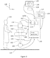
- FIG. 1B An example of a more detailed layout of a multiple frames imaging clinical environment according to the present invention is described in FIG. 1B .
- Operator 122 presses foot switch 124 to activate the x-ray.
- Input device 128 provides indication of one or more ROIs. This information is typically provided relative to monitor 118 .
- This information, the at least one desired center of ROI may be provided for example in terms of (X,Z) coordinates, in the plane of monitor 118 , using coordinate system 126 . It would be appreciated that in this example the plane of monitor 118 and therefore also image 120 are parallel to the (X,Z) plane of coordinate system 126 .
- Other coordinate systems are possible, including coordinate systems that are bundled to monitor 118 and rotate with monitor 118 when it is rotated relative to coordinate system 126 .
- controller 127 which is basically a computer, such as any PC computer.
- Box 150 in FIG. 1B represents a collimator according to the present invention, for example, the collimator of FIGS. 4 through 11 .
- Box 150 can be located under collimator 104 , above collimator 104 as shown by numerical reference 150 A or instead of collimator 104 (not shown in FIG. 1B ).
- the collimators represented by boxes 150 and 150 A are controlled by controller 127 .
- X-ray emission is also controlled by controller 127 , typically through x-ray controller 130 .
- the collimator partially blocks radiation, depending on the determined at least one desired center of ROI (step 2720 ). Part of the x-rays are absorbed by the patient 110 (step 2730 ) and the remaining radiation arrives at the image intensifier 114 (step 2740 ).
- the image is intensified and captured by a camera 116 and in step 2760 the captured image is transferred to the image processor 117 and in step 2770 the processed image is displayed on monitor 120 .
- Image processor 117 may assume many forms and may be incorporated in the current invention in different ways.
- image processor 117 includes two main sub units: 117 A provides basic image correction such as pixel non-uniformity (dark offset, sensitivity, reconstruction of dead pixels etc), 117 C provides image enhancement processing (such as noise reduction, un-sharp masking, gamma correction etc).
- image from sub-unit 117 A is transferred for further processing in sub-unit 117 C.
- the sub-units of image processor 117 can be supported each by a dedicated hardware but they can also be logical sub-units that are supported by any hardware.
- controller 127 processes the image as required from using any of the collimators represented by box 150 and returns the processed image to sub-unit 117 C for image enhancement.
- controller 127 does not have to take place in controller 127 and it can be executed by a third sub-unit 117 B (not shown in FIG. 1B ) located between 117 A and 117 C.
- Sub-unit 117 B can also be only a logical process performed anywhere in image processor 117 .
- x-ray controller 130 is presented here in the broad sense of system controller. As such it may also communicate with image processor 117 to determine its operating parameters and receive information as shown by communication line 132 , It may control image intensifier 114 , for example for zoom parameters (communication line not shown), it may control camera 116 parameters (communication line not shown), it may control the c-arm and bed position (communication line not shown) and it may control x-ray tube 100 and collimator 104 operation parameters (communication line not shown).
- image processor 117 may also communicate with image processor 117 to determine its operating parameters and receive information as shown by communication line 132 , It may control image intensifier 114 , for example for zoom parameters (communication line not shown), it may control camera 116 parameters (communication line not shown), it may control the c-arm and bed position (communication line not shown) and it may control x-ray tube 100 and collimator 104 operation parameters (communication line not shown).
- x-ray controller 130 There may be a user interface for operator 122 or other staff members to input requests or any other needs to x-ray controller 130 (not shown).
- x-ray controller 130 may contain one or more computers and suitable software to support the required functionality.
- An example for such a system with an x-ray controller is mobile c-arm OEC 9900 Elite available from GE OEC Medical Systems, Inc., Salt Lake City, Utah USA. It would be appreciated that the exemplary system is not identical to the system of FIGS. 1B and 1 s only provided as a general example. Some of these features are shown in FIG. 3 .
- FIG. 2 illustrating an example of an image 120 displayed on monitor 118 .
- dashed circle line 204 indicates the border between segment 200 of the image and segment 202 of the image, both segments constitute the entire image 120 .
- it is desired to get a good image quality in segment 200 meaning higher x-ray DPP for segment 200 and it is acceptable to have a lower image quality in segment 202 , meaning lower DPP for segment 202 .
- the two segments 200 and 202 are provided here only as one example of an embodiment of the invention that is not limited to this example and that image 120 can be divided to any set of segments by controlling the shape of the apertures in the collimators and mode of motion of the collimators. Such examples are provided below.
- DPP should be interpreted as the x-ray dose delivered towards a segment representing one pixel of image 120 to generate the pixel readout value used to construct image 120 (excluding absorption by the patient or other elements which are not a part of the system, such as the hands and tools of the operator).
- pixels with different DPP per the collimator design and use are normalized to provide a proper display-frame.
- Normalization scheme is made in accordance with the x-ray exposure scheme (i.e., collimator shape, speed and position). Such normalization can be done on the basis of theoretical parameters.
- Collimators according to this invention can be mounted on an x-ray system as stand-alone or together with another collimator, for example, such that is designed to limit the x-ray to a part of input area 112 of the image intensifier. Collimators of the invention and other collimators may be placed in any order along the x-ray path.
- the exposed part of area 112 is the remaining of the superposition of the area of all the collimators in the path of the x-ray block. In the design of such successive arrangement, the distances of each of the collimators from the x-ray source and distance to area 112 needs to be considered with the geometry of the collimators, as described above, to get the desired functionality.
- the at least one ROI becomes the area used for image optimization.
- the input device provides the ROI coordinates of the at least one user on the screen.
- the ROIs are moved to these coordinates, with a complementary adjustment of the collimator and the optimization is made for the image included in the ROIs.
- the image may be optimized per the ROIs' content using any of the above mentioned parameters or any other parameter that modifies the displayed value of a pixel in the image.
- FIG. 3 presents an exemplary system for carrying out the invention.
- an ROI that is centered in image 120 (such as ROI 200 of FIG. 2 ) and has a fixed position is used for image analysis and for generating parameters to drive x-ray tube 100 and modify image 120 .
- Parameters such as average value, maximum value and contrast may be calculated for this area.
- Such parameters are typically used to optimize the x-ray tube operation (such as mA, mAs and KVp).
- an input device 127 is used to provide x-ray controller 130 with the ROI coordinates of one or more users 122 .
- the input device can be any input device that affects the position and/or the shape of the ROI.
- an eye tracker, a joy-stick, a keyboard, an interactive display, a gesture reading device, a voice interpreter or any other suitable device can be used to determine coordinates relative to image 120 , and the ROI position and/or shape changes according to such input.
- some of the input devices may need a user interface 129 .
- the user interface can have any display, operated by any computer or tablet, use mouse, trackball or touch-screen, joystick or hand gesture to control the selection of the ROI.
- Essentially non-overlapping filters means a design that is intended to support the above system characteristics in at least most of the image area. A small overlapping that, for example results in extra filtering along overlapping edges of two adjacent filters would still be included in “essentially non-overlapping”
- FIG. 4 providing an exemplary collimator 4500 according to the present invention.
- Collimator 4500 comprises four plates 4501 , 4502 , 4503 and 4504 that are opaque or partially transparent to x-ray. In this example we shall assume that each such plate transmits 10% of beam 106 but it would be appreciated that other transmission levels may be contemplated. Plates 4501 , 4502 , 4503 and 4504 can be made from any suitable material, considering the desired effect of the spectral distribution of the transmitted x-ray beam. For example, copper or aluminum plates can be used.
- Dashed circle 106 A ( FIG. 4A ) represents x-ray cone 106 cross section at generally the plane of collimator 4500 . Except for a rectangular shaped x-ray beam portion 3510 ( FIG. 4A ), the rest of the beam intensity is reduced due to plates 4501 , 4502 , 4503 and 4504 .
- Eight motors can move plates 4501 , 4502 , 4503 and 4504 as explained below.
- the components of the motorizing elements are detailed in reference to plate 4501 .
- the other 3 plates' mechanisms are analogous.
- Motor 4501 A drives screw 4501 C that moves nut 4501 E.
- Nut 4501 E is connected to plate 4501 , therefore enables plate 4501 to move in the directions of arrow 4501 F.
- Motor 4501 B drives screw 4501 D that moves nut 4501 E.
- Nut 4501 E is connected to plate 4501 therefore enables plate 4501 to move in directions of arrow 4501 G.
- each plate can move as indicated by dual-head arrows for each plate, independently of the other plates.
- An example of possible arrangement of nut 4501 E is shown in FIG. 4.1 .
- Rails 4505 A may be used to support the plates and enable motion. Motors 4501 A and 4501 B slide freely on the rails 4505 A according to the mentioned directions.
- each one of two adjacent edges of a filter (plate) is parallel and in contact with the edge of a neighboring filter as demonstrated in FIG. 4 .
- the collimator 4500 is based on “active coupling”, meaning the controller of the motors has to ensure coupling of the plates where coupling of two plates means they are in contact along at least a part of an edge.
- each plate is able to move independently but in order to prevent radiation penetration between the plates the controller ensures that when a plate moves in direction perpendicular to a coupling line, the adjacent plate coupled along this line moves with it and thus coupling is maintained. Namely, when one motor needs to be moved, the controller may move other motors as well, to maintain plates coupling.
- coupling is not required at all times and it is typically preferred to have the coupling at least when radiation is turned on.
- a circular image/circular cone shape x-ray beam is only an example.
- the x-ray beam and the image may be rectangular or any other shape, depending on the c-arm and collimator setup.
- aperture 3512 is in the region of beam 106 (as shown by the beam cross section 106 A) and has a certain size dictated by the required ROI.
- FIG. 4A demonstrates an adjustment of plates 4501 , 4502 , 4503 and 4504 in order to create the required aperture for providing radiation to the ROI that is different from the ROI example shape of FIG. 4 .
- ROI 3602 of image 120 cannot only be moved across the area of image 120 to the desired location but also the size and aspect ratio of the ROI can be changed as desired, to compensate for zoom in image intensifier 114 ( FIG. 1A ) or for other reasons.
- FIG. 5 illustrating the x-ray intensity distribution in different areas of image 120 when the image ROI 3602 is in the position resulting from mechanical ROI 3512 presented in FIG. 4A .
- there is no object (patient) between collimator 4500 and input area 112 so, ideally, without additional conventional collimator blocking radiation, the x-ray radiation over input area 112 , outside of the ROI, would be uniform (up to specific system inherent uniformity limitations).
- the area of image 120 is divided into two intensity areas: 3602 , the ROI, where the original 100% intensity is and 3604 A where the intensity is 10% of that at the ROI.
- FIG. 6 providing an example of collimator 4700 according to the present invention.
- Collimator 4700 uses four motors instead of the eight motors used in the configuration of FIG. 4 .
- Motor 4701 A drives screw 4701 B that moves nut 4701 C.
- Nut 4701 C is connected to plate 4701 , therefore enables plate 4701 to move in the directions of arrow 4701 D.
- An “L” shaped coupler 4705 connects plates 4701 and 4704 wherein nut 4701 C slides on the coupler side 4705 A and plate 4704 is fixedly connected to the other side 4705 B of the coupler via a connector 4706 .
- plate 4701 moves in the directions of arrow 4701 D
- plate 4704 moves with it in the same direction but in order to move in the directions of arrow 4701 E
- plate 4702 moves and moves plate 4701 with it.
- the collimator 4700 is based on “passive coupling” meaning the “L” shaped couplers ensure coupling of the plates by forcing two adjacent edges of neighboring plates to maintain their relative positions by sliding along each other.
- the four motors slide freely on the rails 4505 B according to the mentioned directions.
- some of the plates may be movable by one motor and a coupler and some plates may be movable by two motors.
- each of two adjacent edges of a filter (plate) is parallel and in contact with the edge of a neighboring filter.
- FIG. 6A Reference is made now to FIG. 6A .
- FIG. 6A demonstrates an adjustment of plates 4701 , 4702 , 4703 and 4704 in order to create the aperture for providing radiation to the ROI.
- the ROI of image 120 can not only be moved across the area of image 120 to the desired location but also the size and aspect ratio of the ROI can be changed as desired, to compensate for zoom in image intensifier 114 or for other reasons.
- FIG. 7 providing an example of collimator 4800 of the present invention.
- Collimator 4800 also uses four motors instead of eight.
- the components of the motorizing elements are detailed in reference to plate 4801 .
- the other 3 plates' mechanisms are analogous.
- Motor 4801 A drives screw 4801 B that moves nut 4801 C.
- Nut 4801 C is connected to plate 4801 therefore enables plate 4801 to move in the directions of arrow 4801 D.
- a “U” shaped coupler 4805 connects plates 4801 and 4804 wherein nut 4801 C slides on the coupler side 4805 A and nut 4804 A slides on the coupler side 4805 B.
- the connector 4806 is fixedly connected to the rail 4505 C and allows the coupler to slide through it.
- the “U” shaped coupler dictates the motion limitations and ensures plates' coupling.
- plate 4801 moves in the directions of arrow 4801 D
- plate 4804 moves with it in the same direction but in order to move in the directions of arrow 4801 E
- plate 4802 moves and moves plate 4801 with it.
- the collimator 4800 is based on “passive coupling” meaning the “U” shaped coupler ensures coupling of the plates by forcing two adjacent edges of neighboring plates to maintain their relative positions by sliding along each other.
- the motors slide freely on the rails 4505 C according to the mentioned directions.
- some of the plates may be movable by one motor and a coupler and some plates may be movable by two motors.
- each of two adjacent edges of a filter (plate) is parallel and in contact with the edge of a neighboring filter.
- FIG. 7A Reference is made now to FIG. 7A .
- aperture 3512 is at the region of beam 106 (as shown by the beam cross section 106 A) and it has a certain size.
- FIG. 7A demonstrates an adjustment of plates 4801 , 4802 , 4803 and 4804 in order to create the aperture for providing radiation to the ROI.
- the ROI of image 120 can not only be moved across the area of image 120 to the desired location but also the size and aspect ratio of the ROI can be changed as desired, to compensate for zoom in image intensifier 114 or for other reasons.
- FIG. 11 providing an example of collimator 5400 of the present invention.
- Collimator 5400 also uses four motors instead of eight.
- the components of the motorizing elements are detailed in reference to plate 5401 .
- the other 3 plates' mechanisms are analogous.
- Motor 5401 A moves on rail 4505 G and connects plates 5401 and 5402 via couplers 5402 A and 5402 B and nuts 5401 B and 5401 C respectively, thereby enabling plate 5401 to move in the directions of arrow 5401 D.
- the nuts 5401 B and 5401 C slide freely on the couplers 5402 A and 5402 B respectively.
- the couplers 5402 A and 5402 B dictate the motion limitations and ensure plates' coupling.
- plate 5401 moves in the directions of arrow 5401 D
- plate 5402 moves with it in the same direction but in order to move in directions of arrow 5401 E
- plate 5404 moves and moves plate 5401 with it.
- the collimator 5400 is based on “passive coupling” meaning the couplers 5402 A and 5402 B ensure coupling of the plates by forcing two adjacent edges of neighbor filters to maintain the distance between them by sliding along each other.
- the motors slide on the rails 4505 G according to the mentioned directions.
- each of two adjacent edges of a filter (plate) is parallel and in contact with the edge of a neighboring filter.
- FIG. 11A Reference is made now to FIG. 11A .
- aperture 3512 is at the region of beam 106 (as shown by the beam cross section 106 A) and it has a certain size.
- FIG. 11A demonstrates an adjustment of plates 5401 , 5402 , 5403 and 5404 in order to create the aperture for providing radiation to the ROI.
- the ROI of image 120 can not only be moved across the area of image 120 to the desired location but also the size and aspect ratio of the ROI can be changed as desired, to compensate for zoom in image intensifier 114 or for other reasons.
- FIG. 8 providing an example of collimator 4900 of the present invention.
- Collimator 4900 has three filters (plates) and uses three motors.
- Motor 4901 A drives screw 4901 B that moves nut 4901 C.
- Nut 4901 C is connected to plate 4901 therefore enables plate 4901 to move in the directions of arrow 4901 F.
- a “U” shaped coupler 4905 connects plates 4901 and 4902 wherein nut 4901 E slides on the coupler side 4905 A and nut 4902 A slides on the coupler side 4905 B.
- the “U” shaped coupler dictates the motion limitations and ensure plates' coupling.
- plate 4901 moves in directions of arrow 4901 F
- plate 4903 moves with it in the directions of arrow 4903 A but in order to move in the directions of arrow 4901 D
- plate 4902 moves in the directions of arrow 4903 A and moves plate 4901 with it.
- the collimator 4900 is based on “passive coupling” meaning the couplers 5402 A and 5402 B ensure coupling of the plates by forcing two adjacent edges of neighbor filters to maintain the distance between them by sliding along each other.
- the motors slide freely on the rails 4505 D according to the mentioned directions.
- some of the plates may be movable by one motor and a coupler and some plates may be movable by two motors.
- FIG. 8A Reference is made now to FIG. 8A .
- FIG. 8A demonstrates an adjustment of plates 4901 , 4902 and 4903 in order to create the aperture for providing radiation to the ROI.
- the ROI of image 120 can not only be moved across the area of image 120 to the desired location but also the size and aspect ratio of the ROI can be changed as desired, to compensate for zoom in image intensifier 114 or for other reasons.
- FIG. 9 providing an example of collimator 5000 of the present invention.
- Collimator 5000 has five plates (filters) and uses five motors.
- the components of the motorizing elements are detailed in reference to plate 5001 .
- the other four plates' mechanisms are analogous.
- Motor 5001 A drives screw 5001 B that moves nut 5001 C.
- Nut 5001 C is connected to plate 5001 thus enabling plate 5001 to move in the directions of arrow 5001 D.
- a “U” shaped coupler 5006 connects plates 5001 and 5002 wherein nut 5001 E slides on the coupler side 5006 A and nut 5002 A slides on the coupler side 5006 B.
- the “U” shaped coupler dictates the motion limitations and ensure plates' coupling.
- plate 5001 moves in directions of arrow 5001 D
- plate 5002 moves with it in the directions of arrow 5002 B but in order to move in the directions of arrow 5001 F
- plate 5005 moves and moves plate 5001 with it.
- the collimator 5000 is based on “passive coupling” meaning the “U” shaped couplers ensure coupling of the plates by forcing two adjacent edges of neighbor filters to maintain the distance between them by sliding along each other.
- the motors slide freely on the rails 4505 E according to the mentioned directions.
- some of the plates may be movable by one motor and a coupler and some plates may be movable by two motors.
- FIG. 9A through 9C Reference is made now to FIG. 9A through 9C .
- aperture 3512 is at the region of beam 106 (as shown by the beam cross section 106 A) and it has a certain size.
- FIG. 9A demonstrates an adjustment of plates 5001 , 5002 , 5003 , 5004 and 5005 in order to create a specific needed pentagonal ROI.
- FIG. 9B demonstrates an adjustment of plates 5001 , 5002 , 5003 , 5004 and 5005 in order to create a specific needed quadrangular ROI.
- FIG. 9C demonstrates an adjustment of plates 5001 , 5002 , 5003 , 5004 and 5005 in order to create a specific needed triangular ROI.
- FIG. 10 providing an example of collimator 5100 of the present invention.
- Collimator 5100 has twelve plates (filters) and uses twelve motors.
- FIG. 10A shows an enlargement of the components of the motorizing elements that are detailed in reference to plate 5101 .
- the other eleven plates' mechanisms are analogous.
- Motor 5101 A drives screw 5101 B that moves nut 5101 C.
- Nut 5101 C is connected to plate 5101 thus enabling plate 5101 to move in the directions of arrow 5101 D.
- a “U” shaped coupler 5106 connects plates 5101 and 5102 wherein nut 5101 E slides on the coupler side 5106 A and nut 5102 A slides on the coupler side 5106 B.
- the “U” shaped coupler dictates the motion limitations and ensures plates' coupling.
- plate 5101 moves in the directions of arrow 5101 D
- plate 5102 moves with it in the same direction but in order to move in directions of arrow 5101 F
- plate 5112 moves and moves plate 5101 with it.
- the collimator 5100 is based on “passive coupling” meaning the “U” shaped couplers ensure coupling of the plates by forcing two adjacent edges of neighbor filters to maintain the distance between them by sliding along each other.
- the motors slide freely on the rails 4505 F according to the mentioned directions.
- some of the plates may be movable by one motor and a coupler and some plates may be movable by two motors.
- FIGS. 10B and 10C demonstrate an adjustment of plates 5101 through 5112 in order to create a specific ROI such as 3512 B and 3512 C.
- a problem that may occur while using the “essentially non-overlapping filters” collimators aforementioned is a penetration of X-Ray radiation between the collimator plates.
- FIG. 12A demonstrates the use of “straight edge” plates with radiation beam 5320 penetrating the filtering layer through a small gap between plates 5322 and 5324 . This makes the line along which the two plates meet visible on the image as illustrated on resulting image 5326 .
- FIGS. 12B and 12C offer two solutions to the problem.
- FIG. 12B demonstrates the use of “V shaped edge” plate with a negative or reversed V edge plate fitting each other so that ray 5320 A cannot pass through the line of plates contact without being filtered.
- the resulting image 5326 A without the effect of radiation un-intended penetration is shown.
- FIG. 12C demonstrates the use of “tapered edge” plates and the resulting image.
- edge shapes are considered, such as arcuate, concave, convex, contoured, or stepped, or any complementary, mating edge shape that effectively prevent line-of sight through the abutting plates along the primary direction of beam travel.
- FIGS. 12D and 12E provide another example for the coupling concept of the present invention.
- plates 5302 and 5304 of FIG. 12C are used.
- plates 5302 and 5304 are not in the same plane.
- Plate 5304 is further away from radiation source 5306 , in direction perpendicular to the planes of plates 5302 and 5304 .
- plates 5302 and 5304 are shown to the right of radiation source 5306 .
- the horizontal distance between plates 5302 and 5304 is set so that radiation rays passing through each of the filters and in the zone including both filters experience essentially the same filtering.
- ray 5311 is passing through plate 5302 only
- ray 5313 is passing through plate 5304 only
- ray 5312 passes through both plates 5302 and 5304 .
- the horizontal distance between plates 5302 and 5304 is set so that all 3 rays experience essentially the same thickness of filtering.
- plates 5302 and 5304 are shown to the left of radiation source 5306 .
- Ray 5311 A passes through plate 5302 only
- ray 5313 A passes through plate 5304 only
- ray 5312 A passes through both plates 5302 and 5304 .
- the horizontal distance between plates 5302 and 5304 is set so that all 3 rays experience essentially the same thickness of filtering. Note that the horizontal distance between plates 5302 and 5304 in FIG. 12E is smaller than in FIG. 12D . This is because the change in the angle of incidence of the radiation rays. This demonstrates the concept of plates that are “coupled” in this invention.
- FIG. 13 shows an exemplary user interface which may be implemented as part of a control application running on an electronic device having an interactive display, such as a tablet, a monitor or a smartphone.
- the application communicates with the controller 132 and displays the captured and corrected x-ray image.
- the user uses four sliders 10201 to determine ROI 10210 size and location according to the area encodes by border lines 10201 A, a rotation button 10202 to determine a rotation direction of the selected ROI (clockwise or anticlockwise) and initiates a rotation of the ROI accordingly until released, a displacement button 10203 for moving the selected ROI without changing its size and orientation and an optional “GO” button 10204 for implementing the actual motion of the collimator plates according to the indicated location, orientation and aperture size.
- the plates' motion could starts each time the buttons are released or, in another example, after a predetermined time period with no changes in the interface setup.
- FIG. 13A is another example of a user interface.
- the user marks any enclosing shape such as shape 10205 on the screen and the collimator plates are arranged in a position where they form an aperture that best encloses the shape.
- “GO” button 10204 is optional.
- the plates' motion could starts each time the user stops drawing, or in another example, after the user removes his finger or drawing pen from a touch screen, or, in another example, after a predetermined time period with no changes in the interface setup.
- FIG. 13B is another example that is implemented on the same user interface as in FIG. 13A .
- the user marks any shape such as line 10206 on the screen and the collimator plates are arranged in a position where they form an aperture that best encloses the shape.
- the plates' motion could starts each time the user stops drawing, or in another example, after the user removes his finger or drawing pen from a touch screen, or, in another example, after a predetermined time period with no changes in the interface setup.
- FIG. 13C is another example that is implemented on the same user interface as in FIG. 13A .
- the user marks more than one shape such as lines 10207 A and 10207 B on the screen and the collimator plates are arranged in a position where they form an aperture that best encloses the shapes.
- the plates' motion could start each time the user stops drawing a shape segment.
- the plates' motion could start after a predetermined time period with no changes in the interface setup.
- FIG. 13D is another example that is implemented on the same user interface as in FIG. 13A .
- the user marks more than one shape such as lines 10207 A and 10207 B on the screen and the collimator plates are arranged and rotated in a position where they form the smallest aperture that encloses the shapes.
- the aperture shape is fixed.
- FIG. 13E is another example that is implemented on the same user interface as in FIG. 13A .
- the user marks more than one shape such as lines 10207 A and 102078 on the screen and the collimator plates are arranged and rotated in a position where they form the smallest aperture that best encloses the shapes.
- the aperture shape may be changed.
- FIG. 13F is another example that is implemented on the same user interface as in FIG. 13A .
- the user marks any shape such as line 10206 on the screen and the collimator plates are arranged in a position where they form an aperture that encloses the shape.
- the nearest edge to that point could move in parallel to its direction to that point so that calculated ROI 10212 changes to ROI 10222 .
- the aperture shape is fixed.
- FIG. 13G is another example, if the of the point 10220 A to two nearest edges of the ROI is below some determined value, the corner where these two lines meet could move to the marked point so that calculated ROI 10212 changes to ROI 10222 A.
- the aperture shape may be changed.
- the user may use another method of ROI selection (on top of the described in conjunction with FIGS. 13A-G ).
- One may tap on the screen and the collimator plates are arranged in such a position where they form an aperture accordingly, according to, but not limited to, one of the following options:
- the plates' motion could starts each time the user removes his finger or drawing pen from a touch screen, or, in another example, after a predetermined time period with no changes in the interface setup.
- the final ROI 10212 may need to include at least one predetermined location 1306 in the Field of View (FOV).
- FOV Field of View
- the collimator plates are arranged and/or rotated in a position where they form the smallest possible aperture so that higher radiation intensity area best encloses the selected ROI 1302 including the at least one predetermined location 1306 .
- the user interface of the present invention may be used with any collimator capable of moving an aperture, create an aperture, or form a shape in a desired location.
- the user interface may enable the user to:
- FIG. 13K A block diagram of such automatic following of an organ is shown in FIG. 13K .
- At least one first image is received by the imaging system ( 1311 ).
- An organ or object is identified automatically or manually by the user ( 1312 ).
- An organ detector or object detector keeps tracking the motion of the identified organ/object ( 1313 ) and provides the ROI controller ( 1314 ) with information of the location of the organ/object in the image.
- the ROI controller send the required ROI position to the motors control ( 1315 ) that sends motion instructions to the motors, that in turn, move the ROI to include the organ/object ( 1316 ).
- At least one second image is received ( 1317 ) and the process repeats.
- the organ/object tracking does not have to be synchronized in a loop with the at least one second images but it can run, independently on any, typically latest image received, each time tracking calculation cycle starts.
- the system may enable the user to lock the selected ROI and move it to a different location on the screen according to measurements received from a tracking device, such as, for example, an eye tracker, a hand gesture tracking device, by a voice command, etc.
- a tracking device such as, for example, an eye tracker, a hand gesture tracking device, by a voice command, etc.
- the system may enable to automatically move or change the size of a selected ROI based on the movement of the patient and/or the table, on which the patient is lying, and/or the movement of a medical device inserted into the patient's body.
- the ROI may be moved automatically, following that organ, when the patient and/or the table, on which the patient is lying, moves.
- this locking method the system can use image processing with registration and temporal movement detection to determine the changed location of the center of the captured organ and use this path as if the user virtually dragged the locked ROI by himself.
- the system may change the ROI shape according to the movement or zoom changes in order to make sure that the organ is covered by, or included in, the ROI.
- ROI 10212 borders could be automatically calculated and set in a variety of methods including:
- FIGS. 13A-13D and 13F an enclosing rectangle is shown, which corresponds to a rectangular aperture such as shown in conjunction with the collimator of FIGS. 4-7 , as will be explained below.
- an enclosing quadrilateral is shown, which corresponds to a quadrilateral aperture such as shown in conjunction with an embodiment of the collimator of FIG. 8-10
- the user interface can be operated using touch screen or any other input device such as a computer mouse.
- Both user interface options may be active at the same time and the user may select the most appropriate one.
- any collimator described herein and any other existing or future collimator may be added to an existing multiple frame imaging system as a retrofit, mechanically connected with the C-Arm and mounted between the existing collimator and the patient.
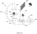
- FIG. 14 depicts schematically such a system 5500 comprising an X-ray source 5510 , an original collimator 5515 , an additional collimator 5520 according to the present invention, a patient 5530 , a C-Arm 5535 , a detector 5540 , an X-Ray controller 5550 , an X-Ray operating pedal 5560 , an exemplary user interface device joy stick 5570 and a display 5580 .
- the new system controller 5565 is connected with the detector 5540 to receiver therefrom detected images, image process them as described above in conjunction with the various embodiments, displays the corrected image on the display 5580 and controls the collimator 5520 according to inputs from the joy stick (or tablet or any other user interface device capable of indicating a required ROI relative to a displayed image).
- Display 5580 may display the image obtained through both collimators without image correction, the image obtained through both collimators with image correction and the image obtained through the original collimator only.
- the user interface device may provide selection between the two collimators to determine which collimator is currently addressed. Furthermore, when the original collimator is selected for operation/activation the newly inserted collimator would translate in parallel with the X-Ray detector plane and move out of the X Ray beam pathway so that not to effect the beam.
- the additional collimator 5520 may be connected to the original collimator 5515 , or to the radiation tube or to the c-arm by mechanical or other connection means as will be explained bellow in FIGS. 16-19A .
- FIG. 15 is another embodiment of the system of FIG. 14 according to the present invention.
- the additional collimator 5520 may also be driven by a robotic arm 5610 such as for example in coordination with the original collimator 5515 , such that the new collimator moves and functions while being mechanically supported on its own base without necessarily being mechanically attached to any moving section of the original X-ray system.
- a robotic arm will use electronic sensors and controllers to provide accurate tracking motion as needed to perform the collimation function of the new collimator which is attached to the end effector/gripper/hand of the robot.
- the “robotic arm” may be controlled by use of:
- the additional collimator 5520 may be connected to the original collimator 5515 , or to the radiation tube or to the c-arm by mechanical or other connection means.
- FIG. 16 is an example of such mechanical connection.
- Collimator 5520 is steadily mounted via adapter 5700 to the c-arm 5710 by screws, glue, welding, etc. 5720 that ensure coupling of the adapter and the collimator.
- FIG. 16A is a top view of the system of FIG. 16 .
- FIG. 17 is another example of a mechanical connection.
- Collimator 5520 is steadily mounted via adapter 5810 to the original collimator cover or to the radiation tube cover 5820 by screws, glue, welding, etc. 5830 that ensure coupling of the collimator.
- FIGS. 17A and 17B are side views of the system of FIG. 17 .
- FIG. 18 is another example of a mechanical connection.
- Collimator 5520 is steadily mounted via adapter 5910 to the original collimator cover or to the radiation tube cover 5920 by screws, glue, welding, etc. 5930 that ensure coupling of the collimator.
- the adapter additionally comprises a rotation unit comprising a motor 5940 and a slew bearing 5950 . After the collimator 5520 is mounted, it can be rotated using this rotation unit.
- Sensors 5960 may be placed in each corner of the collimator 5520 (two not shown) in order to prevent collision, for example, with the c-arm.
- FIG. 18A is an example of the system of FIG. 18 when collimator 5520 is rotated.
- FIG. 19 is another example of a mechanical connection.
- Collimator 5520 is steadily mounted via adapter 6010 to the c-arm cabinet 6020 .
- the adapter may be connected anywhere on the c-arm cabinet or rest on wheels on the floor, typically next to cabinet 6020 or the cabinet wheels (not shown).
- adaptor 6010 If it is coupled to the cabinet, it travels with it.
- the motions of adaptor 6010 components are the same as the c-arm analog components in directions of dual head arrows 6030 - 6060 (shown in FIG. 19A ).
- FIG. 19A is a side view of the system of FIG. 19 with direction dual head arrows 6030 - 6050 .
- component 6031 adaptor 6010 is coupled to c-arm component 6032 and whenever c-arm part 6032 moves, adaptor component 6031 follows it and maintains its' position relative to c-arm component 6032 .
- each component of the c-arm “arm” that holds collimator 5920 has the analog component in adaptor 6010 that is coupled to it, and moves with it maintaining the relative position.
- the system may use a multiple holes collimator.
- FIG. 20A shows an exemplary collimator 3410 having three holes for ROI of three different sizes.
- each ROI hole diameter is designed to project 1 ⁇ 3 of the exposed area diameter.
- image intensifier input area 112 diameter is 12′′ and it has 2 zoom options 9′′ and 6′′ then hole 3414 will be 9/12 of hole 3412 and hole 3416 will be 6/12 of hole 3412 in diameter.
- the corresponding area of collimator 3410 is used so that the ROI is maintained 1 ⁇ 3 in diameter of image 120 diameter.
- FIG. 20B shows another exemplary collimator 3420 enabling adjustment of ROI hole to the zoom options of the image intensifier 114 in a similar manner to collimator 3410 but with a different geometry and holes 3422 , 3424 , 3426 and 3428 .
- Rectangular hole 3428 (that can also be a relatively large circular hole) provides a collimator area which does not limit the x-ray and enables conventional usage of such system.
- collimators with a plurality of holes such as those of FIGS. 20A and 20B can also be moved perpendicularly to the collimator plane to provide variable size ROI onto input area 112 and/or also may be rotated.
- collimators with a plurality of holes such as those of FIGS. 20A and 20B can also be moved perpendicularly to the collimator plane to provide variable size ROI onto input area 112 and/or also may be rotated.
- more ROI sizes can be provided with reduced vertical movement range comparing to one hole.
- FIGS. 20A and 20B can be combined with any of the edges as shown in FIGS. 12A to 12E .
- FIG. 21A providing another example of collimator 3500 of the present invention.
- Coordinate system 126 is present in FIG. 21A to provide orientation in reference to FIG. 1B .
- X-ray focal point 306 is shown and a cone-shaped x-ray beam 107 is projected upwards towards input area 112 (not shown—see, e.g., FIG. 1B ).
- Plates 3501 , 3502 , 3503 and 3504 are partially transparent to x-ray. In this example we shall assume that each such plate transmits 30% of beam 107 but it would be appreciated that other transmission levels are available. Plates 3501 , 3502 , 3503 and 3504 can be made from any suitable material, considering the desired effect of the spectral distribution of the transmitted x-ray beam. For example, copper plates can be used.
- Dashed circle 107 A represents x-ray cone 107 cross section at generally the plane of collimator 3500 . Except for a rectangular shaped x-ray beam, 3510 , the rest of the beam ( 107 B) intensity is reduced due to plates 3501 , 3502 , 3503 and 3504 . Where there is only one layer of plates the x-ray beam is reduced to 30% of its original intensity. In areas where two plates overlap the x-ray beam is reduced to 9% of its original intensity (30% ⁇ 30%), With this example ROI 3510 is now rectangular. Motors can move plates 3501 , 3502 , 3503 and 3504 as explained in FIG. 21B .
- FIG. 21B the components of the motorizing elements are detailed in reference to plate 3501 .
- the other 3 plate's mechanisms are analogue.
- Motor 3501 A drives screw 3501 C that moves nut 3501 B.
- Nut 3501 B is connected to plate 3501 therefore enables plate 3501 to move in directions of arrow 3501 D. Therefore, each plate can move independently of the other plates as indicated by dual-head arrow for each plate. Rails that may be used to support the plates and enable motion are not shown in this figure. It would be appreciated that the specific motion mechanism described here is provided to explain the invention and that the scope of the invention is not limited to this motion mechanism.
- hole 3512 is at the center of beam 107 (as shown by the beam cross section 107 A) and it has a certain size.
- plates 3503 and 3504 were moved to the right without changing the distance between these plates. Plates 3501 and 3502 were moved upwards without changing the distance between these plates. As a result hole 3512 moved towards the top-right edge of x-ray beam cross-section 107 A but without changing its' dimensions.
- hole 3512 is also generally at the top-right area of x-ray beam cross-section 107 A but the distance between plates 3501 and 3502 was reduced and also the distance between plates 3503 and 3504 was reduced. As a result, the size of hole 3512 was reduced and the resultant ROI is smaller now.
- FIG. 21E the hole is still in the upper-right area of x-ray beam cross-section 107 A but the distance between plates was changed again to produce a large rectangle that is also particularly longer in the Y direction than in the X direction.
- the ROI therefore becomes larger and also of a different shape.
- the ROI of image 120 A can not only be moved across the area of image 120 A to the desired location but also the size and aspect ratio of the ROI can be changed as desired, to compensate for zoom in image intensifier 114 or for other reasons.
- FIG. 21A implies that pairs of collimator plates are arranged in the same plane, this is not a limitation of the invention and each of the plates of a plates pair can be positioned in a different plane.
- FIG. 22 illustrating the x-ray intensity distribution in different areas of image 120 A when the ROI is in the position presented in FIG. 21B .
- there is no object (patient) between collimator 3500 and input area 112 so, ideally, without collimator 3500 the x-ray radiation over input area 112 would be uniform.
- the area of image 120 A is divided to 3 intensity areas: 3602 , the ROI, where the original 100% intensity is, 3604 (4 such areas) where the intensity is 30% of the ROI and 3606 (4 such areas) where the intensity is 9% of the ROI.
- any of the above described collimator's plates and collimators may be partially transparent to x-ray radiation.
- collimator's plates and collimators are not limited to be partially transparent and may be opaque.
- any one of the collimator's holes may be used for any desired ROI.
- the shape of the holes is not limited to the shape shown and any shape may be used.
Landscapes
- Health & Medical Sciences (AREA)
- Life Sciences & Earth Sciences (AREA)
- Engineering & Computer Science (AREA)
- Medical Informatics (AREA)
- Physics & Mathematics (AREA)
- High Energy & Nuclear Physics (AREA)
- Heart & Thoracic Surgery (AREA)
- Animal Behavior & Ethology (AREA)
- Optics & Photonics (AREA)
- Pathology (AREA)
- Radiology & Medical Imaging (AREA)
- Biomedical Technology (AREA)
- Biophysics (AREA)
- Molecular Biology (AREA)
- Surgery (AREA)
- Nuclear Medicine, Radiotherapy & Molecular Imaging (AREA)
- General Health & Medical Sciences (AREA)
- Public Health (AREA)
- Veterinary Medicine (AREA)
- Human Computer Interaction (AREA)
- Computer Vision & Pattern Recognition (AREA)
- Automation & Control Theory (AREA)
- Robotics (AREA)
- Spectroscopy & Molecular Physics (AREA)
- General Engineering & Computer Science (AREA)
- Apparatus For Radiation Diagnosis (AREA)
Abstract
Description
- 1. A first part of the image represents the ROI: unfiltered radiation section (100% of the radiation arriving at the collimator plates)
- 2. A second part of the image is background, where radiation is filtered by the collimator plates (100%>radiation≥0 of the radiation arriving at the collimator plates)
- 3. The background filter comprises at least three separate filters
- 4. The background image area comprises at least one point at one filter area of the image and at least one point at a second filter area of the image;
- 5. There is at least one contour, connecting these two points, wherein, the radiation along the contour encounters essentially the same filtering characteristics (same total filtering thickness for example, of filters of a uniform material composition).
-
- 1. A predetermined circle around the tap is recognized as the location of the desired ROI (as if the user has drawn that circle by himself to set an ROI) and the collimator plates are arranged and/or rotated in a position where they form spatial radiation modulation according to that predetermined circle; or
- 2. A predetermined circle around the tap is recognized as the location of the desired ROI (as if the user has drawn that circle by himself to set an ROI) and the collimator plates are arranged and/or rotated in a position where they form the smallest possible aperture so that higher radiation intensity area best encloses that circle on the image; or
- 3. (
FIG. 13H ) Apredetermined shape 1302 around thetap 1301 is recognized as the location of the desired ROI (as if the user has drawn that predetermined shape by himself to set an ROI) and the collimator plates are arranged and/or rotated in a position where they form higher radiation intensity area to fit, as possible, that predetermined shape on the image; or - 4. (
FIG. 13I ) Apredetermined shape 1304 around thetap 1303 is recognized as the location of the desired ROI (as if the user has drawn that predetermined shape by himself to set an ROI) and the collimator plates are arranged and/or rotated in a position where they form the smallest possible aperture so that higherradiation intensity area 10212 best encloses that shape on the image; or - 5. Using image processing, the system of the present invention may automatically recognize an organ that includes the tapping location and provides a shape that best encloses that organ, that shape is recognized as the desired ROI and the collimator plates are arranged and/or rotated in a position where they form the smallest possible aperture so that higher radiation intensity area best encloses that desired ROI.
-
- 1. Lock the selected ROI (maintain the shape and size unchanged) and drag it to a different location within the FOV on the screen; or
- 2. Lock the selected ROI and tap on a different location on the screen to automatically move the selected ROI to the new tapping location.
- 3. Lock the selected ROI to automatically follow an organ existing in the selected ROI.
- 1. Closing on the
enclosed area 10214 so that two of the ROI edges are horizontal and located at maximum Y and minimum Y of area 10214 (in reference to coordinatesystem 10216 inFIG. 13A-13C ) at the top and at the bottom ofarea 10214 and two of the ROI edges are vertical and located at maximum X and minimum X of the border ofarea 10214 at the left and at right ofarea 10214. - 2. Same method as (1) but including the marking lines that are outside of
enclosed area 10214. - 3. The method of either (1) or (2) and also rotating the rectangular ROI to an angle that encloses a smaller area. This is demonstrated in
FIG. 13D whereROI 10214 is rotated and each of the edges of the ROI is set, relative to coordinatesystem 10216A that is now rotated, for reference, at thesame angle ROI 10214 is rotated. Also here the edges parallel to the Y direction enclose on the combined shape of 10207A and 102078 in a position of maximum X and minimum X of the combined shape and the edges parallel to the X axis direction enclose on the combined shape of 10207A and 102078 in a position of maximum Y and minimum Y of the combined shape so thatROI 10214 has smaller area thanROI 10212 ofFIG. 13C for the same shape. Different criteria may be involved in determining the ROI shape, size and angle. For example:- 1. Minimal area could be one criterion for setting the ROI angle and borders as described above.
- 2. Aspect ratio could be another criterion to set the ROI angle and borders as described above.
- 3. Minimal ROI dimension could also be used as a criterion for calculating the desired ROI.
- 4. An area or dimension factor criterion could also be used to calculate the desired ROI. For example, the calculated area to enclose with the ROI can be a certain percentage of the minimal area. In another example at least one calculated dimensions of the ROI can be changed by a certain percentage. Such changes could also be done using an additive value (positive or negative) instead or with a percentage value.
- 5. A criterion using a percentage of the entire field of view could be used to calculate the desired ROI. For example, such a criterion could require that the ROI area would be 15% of the area of the field of view. In another example the area of the ROI could include a certain amount of pixels of the image.
- 6. A constraint input by the user could be used also. For example, after setting ROI according to any of the above methods, the user could mark a point outside the ROI (10220 in
FIG. 13F ) and the nearest edge to that point could move in parallel to its direction to that point so thatcalculated ROI 10212 changes to ROI 10222 (FIG. 13F ). In another example, if the difference of the point distances to two nearest edges of the ROI is below some determined value (10220A inFIG. 13G ), the corner where these two lines meet could move to the marked point so thatcalculated ROI 10212 changes toROI 10222A (FIG. 13G ). - 7. The constraints of section (f) above could also be introduced by any of touching at least one of the line images of the ROI and dragging it perpendicularly to its direction and touching at least one of the corner images of the ROI and dragging it in any direction. Such touching and dragging could be done using any input device such as a finger on a touch screen or a mouse of a computer.
- 8. A combination of any of the above criteria could be used to calculate the desired ROI. For example, An ROI with a minimal area could be calculated, then the aspect ratio criterion could be employed to increase the smaller size of the ROI until the aspect ratio limitation is satisfied. Then, if the resulting area is still below any area criterion, the ROI could be increased (maintaining the aspect ratio, angle and center) until the area criterion is satisfied. Following that the user can mark a point near an edge, inside the ROI, and the edge moves to that point (overriding the aspect ratio and area criteria.
- 4. The method of either (1), (2) or (3) and also changing from rectangle to any 4-edges shape enclosing the minimal area, as per the example of
ROI 10218 ofFIG. 13E . - 5. Closing on the drawn
area 10206 so that two of the ROI edges are horizontal and tangent to the border of 10206 area at the top and at the bottom ofarea 10206 and two of the ROI edges are vertical and tangent to the border of 10206 area at the left and at right ofarea 10206. - 6. Closing on the drawn area comprising more than one
drawing 10207A and 102078 so that two of the ROI edges are horizontal and tangent to the border of 10207A and 10207B area at the top and at the bottom ofdrawings drawings - 7. The method of either (5) or (6) and also rotating the rectangular ROI to an angle that encloses the minimal area.
- 8. The method of either (5), (6) or (7) and also changing from rectangle to any 4-edge shape so as to enclose the minimal area.
- 1. Multiple sensors such as optical, magnetic or others that ensure tracking and coordination with the original collimator and X Ray system.
- 2. The
robot controller 5620 communicates directly with (or in some cases may be embedded within) the C-ARM motion controller 5630.
Claims (31)
Priority Applications (1)
| Application Number | Priority Date | Filing Date | Title |
|---|---|---|---|
| US16/885,373 US11213259B2 (en) | 2013-12-11 | 2020-05-28 | X-ray reduction system |
Applications Claiming Priority (5)
| Application Number | Priority Date | Filing Date | Title |
|---|---|---|---|
| US201361914405P | 2013-12-11 | 2013-12-11 | |
| US201461927504P | 2014-01-15 | 2014-01-15 | |
| IBPCT/IB2014/075661 | 2014-10-28 | ||
| US16/158,347 US10695012B2 (en) | 2013-12-11 | 2018-10-12 | X-ray reduction system |
| US16/885,373 US11213259B2 (en) | 2013-12-11 | 2020-05-28 | X-ray reduction system |
Related Parent Applications (1)
| Application Number | Title | Priority Date | Filing Date |
|---|---|---|---|
| US16/158,347 Continuation-In-Part US10695012B2 (en) | 2013-12-11 | 2018-10-12 | X-ray reduction system |
Publications (2)
| Publication Number | Publication Date |
|---|---|
| US20200315552A1 US20200315552A1 (en) | 2020-10-08 |
| US11213259B2 true US11213259B2 (en) | 2022-01-04 |
Family
ID=72662100
Family Applications (1)
| Application Number | Title | Priority Date | Filing Date |
|---|---|---|---|
| US16/885,373 Active US11213259B2 (en) | 2013-12-11 | 2020-05-28 | X-ray reduction system |
Country Status (1)
| Country | Link |
|---|---|
| US (1) | US11213259B2 (en) |
Citations (2)
| Publication number | Priority date | Publication date | Assignee | Title |
|---|---|---|---|---|
| US20130336445A1 (en) * | 2012-06-14 | 2013-12-19 | Carestream Health, Inc. | Roi selection for imaging apparatus |
| US20150223767A1 (en) * | 2012-10-02 | 2015-08-13 | Carestream Health, Inc. | Rapid frame-rate wireless imaging system |
-
2020
- 2020-05-28 US US16/885,373 patent/US11213259B2/en active Active
Patent Citations (2)
| Publication number | Priority date | Publication date | Assignee | Title |
|---|---|---|---|---|
| US20130336445A1 (en) * | 2012-06-14 | 2013-12-19 | Carestream Health, Inc. | Roi selection for imaging apparatus |
| US20150223767A1 (en) * | 2012-10-02 | 2015-08-13 | Carestream Health, Inc. | Rapid frame-rate wireless imaging system |
Also Published As
| Publication number | Publication date |
|---|---|
| US20200315552A1 (en) | 2020-10-08 |
Similar Documents
| Publication | Publication Date | Title |
|---|---|---|
| US10695012B2 (en) | X-ray reduction system | |
| US10327717B2 (en) | X-ray reduction system | |
| US9848840B2 (en) | X-ray diagnostic apparatus comprising an X-ray filter movable along an imaging axis of X-rays | |
| US10285660B2 (en) | X-ray diagnostic apparatus including processing circuitry assigning an input button with an instruction to implement a moving operation | |
| WO2014106783A1 (en) | X-ray reduction system | |
| EP2364648A1 (en) | X-ray imaging apparatus | |
| JP6109650B2 (en) | X-ray diagnostic apparatus, exposure management apparatus, scattered radiation dose distribution forming method, and scattered radiation dose distribution forming program | |
| JP2009136518A (en) | X-ray radiographing apparatus and x-ray radiographing method | |
| JP2017080042A (en) | X-ray image diagnostic apparatus | |
| JP6970203B2 (en) | Computed tomography and positioning of anatomical structures to be imaged | |
| JP5442363B2 (en) | X-ray CT system | |
| CN114098774A (en) | X-ray tube holding device and X-ray imaging system | |
| US11213259B2 (en) | X-ray reduction system | |
| EP3925540A1 (en) | X-ray reduction system | |
| US20120027169A1 (en) | Radiological image radiographing and displaying method and apparatus | |
| CN112472110A (en) | X-ray imaging system and method | |
| US9968313B2 (en) | X-ray tube | |
| JP2019088380A (en) | X-ray diagnostic apparatus and angiography ct apparatus | |
| JP5693650B2 (en) | X-ray imaging apparatus and X-ray imaging method | |
| KR20220092436A (en) | Radiation imaging device and radiation flux control method | |
| JP2005111152A (en) | Surgical x-ray apparatus | |
| CN116963669A (en) | Radiation imaging apparatus and method for controlling radiation beam | |
| TW201542175A (en) | Diagnosis-treatment apparatus collimator region selection control device combined with depth camera | |
| JP2023073627A (en) | X-ray diagnostic device and x-ray image collection method | |
| JP2022009515A (en) | X-ray diagnostic apparatus and angiography ct apparatus |
Legal Events
| Date | Code | Title | Description |
|---|---|---|---|
| FEPP | Fee payment procedure |
Free format text: ENTITY STATUS SET TO UNDISCOUNTED (ORIGINAL EVENT CODE: BIG.); ENTITY STATUS OF PATENT OWNER: SMALL ENTITY |
|
| FEPP | Fee payment procedure |
Free format text: ENTITY STATUS SET TO SMALL (ORIGINAL EVENT CODE: SMAL); ENTITY STATUS OF PATENT OWNER: SMALL ENTITY |
|
| AS | Assignment |
Owner name: CONTROLRAD SYSTEMS, INC, PENNSYLVANIA Free format text: ASSIGNMENT OF ASSIGNORS INTEREST;ASSIGNORS:MELMAN, HAIM ZVI;MELMAN, LIRON;NAVE-FROST, GILAD;AND OTHERS;SIGNING DATES FROM 20200527 TO 20200528;REEL/FRAME:053105/0621 |
|
| STPP | Information on status: patent application and granting procedure in general |
Free format text: DOCKETED NEW CASE - READY FOR EXAMINATION |
|
| STPP | Information on status: patent application and granting procedure in general |
Free format text: NON FINAL ACTION MAILED |
|
| STPP | Information on status: patent application and granting procedure in general |
Free format text: RESPONSE TO NON-FINAL OFFICE ACTION ENTERED AND FORWARDED TO EXAMINER |
|
| STPP | Information on status: patent application and granting procedure in general |
Free format text: NOTICE OF ALLOWANCE MAILED -- APPLICATION RECEIVED IN OFFICE OF PUBLICATIONS |
|
| AS | Assignment |
Owner name: CONTROLRAD, INC., GEORGIA Free format text: CHANGE OF NAME;ASSIGNOR:CONTROLRAD SYSTEMS, INC.;REEL/FRAME:057723/0240 Effective date: 20170221 |
|
| STPP | Information on status: patent application and granting procedure in general |
Free format text: AWAITING TC RESP., ISSUE FEE NOT PAID |
|
| STPP | Information on status: patent application and granting procedure in general |
Free format text: NOTICE OF ALLOWANCE MAILED -- APPLICATION RECEIVED IN OFFICE OF PUBLICATIONS |
|
| STPP | Information on status: patent application and granting procedure in general |
Free format text: PUBLICATIONS -- ISSUE FEE PAYMENT VERIFIED |
|
| STCF | Information on status: patent grant |
Free format text: PATENTED CASE |