US1121237A - Hydraulic accumulator. - Google Patents
Hydraulic accumulator. Download PDFInfo
- Publication number
- US1121237A US1121237A US74826213A US1913748262A US1121237A US 1121237 A US1121237 A US 1121237A US 74826213 A US74826213 A US 74826213A US 1913748262 A US1913748262 A US 1913748262A US 1121237 A US1121237 A US 1121237A
- Authority
- US
- United States
- Prior art keywords
- ram
- accumulator
- head
- packing
- pipe
- Prior art date
- Legal status (The legal status is an assumption and is not a legal conclusion. Google has not performed a legal analysis and makes no representation as to the accuracy of the status listed.)
- Expired - Lifetime
Links
- 238000012856 packing Methods 0.000 description 21
- 210000004907 gland Anatomy 0.000 description 9
- 239000007788 liquid Substances 0.000 description 7
- 238000007789 sealing Methods 0.000 description 6
- 238000005266 casting Methods 0.000 description 3
- 238000010276 construction Methods 0.000 description 3
- 229910001651 emery Inorganic materials 0.000 description 2
- 229910001369 Brass Inorganic materials 0.000 description 1
- 229910000906 Bronze Inorganic materials 0.000 description 1
- 229910000831 Steel Inorganic materials 0.000 description 1
- 239000010951 brass Substances 0.000 description 1
- 239000010974 bronze Substances 0.000 description 1
- 239000004568 cement Substances 0.000 description 1
- 150000001875 compounds Chemical class 0.000 description 1
- KUNSUQLRTQLHQQ-UHFFFAOYSA-N copper tin Chemical compound [Cu].[Sn] KUNSUQLRTQLHQQ-UHFFFAOYSA-N 0.000 description 1
- 230000000630 rising effect Effects 0.000 description 1
- 239000004576 sand Substances 0.000 description 1
- 239000010959 steel Substances 0.000 description 1
- 238000005406 washing Methods 0.000 description 1
- XLYOFNOQVPJJNP-UHFFFAOYSA-N water Substances O XLYOFNOQVPJJNP-UHFFFAOYSA-N 0.000 description 1
Images


Classifications
-
- F—MECHANICAL ENGINEERING; LIGHTING; HEATING; WEAPONS; BLASTING
- F15—FLUID-PRESSURE ACTUATORS; HYDRAULICS OR PNEUMATICS IN GENERAL
- F15B—SYSTEMS ACTING BY MEANS OF FLUIDS IN GENERAL; FLUID-PRESSURE ACTUATORS, e.g. SERVOMOTORS; DETAILS OF FLUID-PRESSURE SYSTEMS, NOT OTHERWISE PROVIDED FOR
- F15B1/00—Installations or systems with accumulators; Supply reservoir or sump assemblies
- F15B1/02—Installations or systems with accumulators
- F15B1/04—Accumulators
- F15B1/08—Accumulators using a gas cushion; Gas charging devices; Indicators or floats therefor
-
- F—MECHANICAL ENGINEERING; LIGHTING; HEATING; WEAPONS; BLASTING
- F15—FLUID-PRESSURE ACTUATORS; HYDRAULICS OR PNEUMATICS IN GENERAL
- F15B—SYSTEMS ACTING BY MEANS OF FLUIDS IN GENERAL; FLUID-PRESSURE ACTUATORS, e.g. SERVOMOTORS; DETAILS OF FLUID-PRESSURE SYSTEMS, NOT OTHERWISE PROVIDED FOR
- F15B2201/00—Accumulators
- F15B2201/20—Accumulator cushioning means
- F15B2201/205—Accumulator cushioning means using gas
Definitions
- This invention V relates to a construction of accumulators capable of giving a plurality of pressures when using a single weight or other constant load.
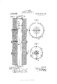
- Figure 1 shows a vertical section of the accumulator and its weights, with the central portion removed to allow the drawing to be made to a larger scale
- Fig. 2 shows a side elevation of the accumulator shown in Fig. 1, with the weights only in section
- Fig. 3 is a plan of the accumulator and weights shown in Figs. 1 and 2
- Fig. 4 1s a cross section of the accumulator taken on a line A AV just below the weights
- Fig. 5 is a cross section of the upper end of the accumulator showing an alternative form of packing
- Fig. 6 shows the arrangement of valves used for the proper control of the accumulator.
- 1 is a bed casting or plate fastened to the foundation 1L by the anchor bolts 2, and plates 3.
- the lower head 4 of the accumulator is fastened to the bed by the studs 5 and nuts 6 and a pipe or ram 7 screws into this head and makes a sealed joint on its lower end.
- This pipe 7 'forms the inner ram of the accumulator.
- Pipes 8 and 9 also screw into this head 4 and make sealed joints at their ends.
- One of these pipes 8, leads to the inside of pipe 7 and the other 9 to the annular space around the pipe 7.
- Pipe 10 forms the outer casing of the accumulator and this is screwed into an annular ring 11.
- the upper end of pipe 10 has a ring 12 similar to ring 11 screwed to it.
- #13 is the upper head of the accumulator and it isfastened to ring 12 by studs 14 and the nuts 15 which produce the pressure to seal the joint between the pipe 10 and the upper head 13.
- This head 13 is provided Specification of Letters Patent.
- #2O is the outer or annular ram of the accumulator and it its and slides in the glands 16 and 1S and in the packing 19 and is preferably made of steel with a polished exterior surface.
- This ram carries a head 20a and a compound packing on its lower end which acts to stop liquid flowing by it in either direction.
- This packing maybe of the form shown here or of any of the usual forms of hydraulic packing.
- This head 2Oa is larger in diameter than the outside of #2O and forms a stop for the accumulator when the ram reaches the upper limit of its motion.
- This annular ram 20 carries on its upper end a circular head 21 fastened to it by bolts 22 which also give the pressure to seal the joint between it and #20.
- An air plug 23 is provided to allow the easy removal of air rising above the liquid used.
- the bolts 24 carry the accumulator weight which may be a single annular casting as shown by #26, Fig. 1, or a series of annular castings as shown by pieces 27, 2S, 29, and 30, Fig. 2, held together by bolts 31 and nuts 32.
- this accumulator permits a plurality of pressures obtainable at any time without changing the load carried at that time.
- This accumulator weight might be made in any oi' the usual forms such as an annular tank filled with water, sand, or cement, but in any case the load is carried by the head 2l, whether made up of all the weights shown connected as in Fig. 2, or any part of them.
- This accumulator, as constructed, with its three cylinders and three different pressures, and its series of weights is a massive structure, and to disassemble it would involve great expense. Yet its packings may have to be replaced quite frequently.
- the head 21 which carries the weights through the bolts 24 is made readily removable,and the ram 20 with its enlarged head 2OCL made readily removable by taking out the bolts 17 and gland 16 with its contained packing gland 18 and packing 19, after which the ram or cylinder 20 can be lifted out with the enlarged head 2Oa and packings carried thereby and these packings then replaced. All this can be done without disturbing the loading weights, or the inner or outer cylinders or the contained liquid.
- Pipe 33 provides a means for the easy removal ofthe leakage at the packing 19.
- Fig. 6 shows the valve system used inv co nection with this accumulator.
- y Pipe l36 leads to the cistern or source "oi supply of the liquid
- pipe 37 leads to the press or other apparatus which is to be operated.
- Valve 38 closes the connection vfrom pipe 8 to 37 valve 39 from pipe 9 to vpipe 37 valve 40 from pipe 8 to pipe 36
- vand valve 41 closes or opens pipe 9 to pipe 36.
- the object of this design is to give three convenient and available pressures of liquid for a given load on the ram, and ⁇ this is done by carrying the load on either the combined area of rams 2O and 7, oron ram 2O alone, lor on ram 7 alone, with results which may be termed low, intermediate and high pressure.
- valves 40 and 41 are closed and valves 38 and 39 open,- and-the load due to the weights and the ram 20 is carried on the combined area, ram 20 sliding in packing 19.
- valves 38 and 41 are closed and 39 and 40 open so that the eective weight acts' only on the area of ram 2O.
- valves 39 Yand 40 are closed and38 and 41 open so that the edective weight acts onthe area of ram 7 that is on the area of its outside diameter corresponding to the inside diameter oi ram'20.
- valves-38 and 39 are closed vand liquid comes from the pump through either or both of valves 42 and 43.
- valves 40 and 43 When through 42 only, valves 40 and 43 are closed, and the pump charges ram 7 only, the ram 20 being lled by liquid directly from the cistern through valve 41. Or one may charge the accumulator by running the pump with valves 41 and 42 closed, while valves 40 and 43 are open, in which case the pump runs much easier but takes longer to raise the weights.
- y such as Ywe-do not use at any particular time.
- a hydraulic accumulator comprising three concentric cylinders, two of which are Xed, the intermediate cylinder being movable and adapted to act as a ram, thel outer and inner cylinders actingas acylinder for theintermediate cylinder when itV isacting as the ram, said inner cylinder being also adapted to act as a ram, 'and the intermedi-f atev cylinder acting as a cylinder for the inner cylinder when it is acting as a ram, this intermediate cylinder having a removable head which closes the pressure-chamber of the inner ram, and extends beyond the walls of the outer cylinder and carries a weight concentric therewith.
Landscapes
- Engineering & Computer Science (AREA)
- Physics & Mathematics (AREA)
- Fluid Mechanics (AREA)
- Mechanical Engineering (AREA)
- General Engineering & Computer Science (AREA)
- Supply Devices, Intensifiers, Converters, And Telemotors (AREA)
Description
Patented Dec. 15, 1914.
3 SHEETSrSHEET l.
A. H. EMBRY.
HYDRAULIC ACGUMULATOR.
APPLICATION FILED IEB,13,1'J13. 1,121,237.
PVTZVESSES 'HE MORRIS PETERS co PHoYo LITHO WASHING 10Nv n C A. H. BMBRY.
HYDRAULIC AGGUMULATOR.
APPLICATION FILED FEB,13,1913.
1,121,237. Patented Dec. 15,1914.
3 SHEETS-SHEET 2.
02./ y@ /1 Homey s HE NORM: r11-TIERS CO,PH0rcALlrfm..wA ulN1. wN. n r
Patented Dec. 15, 1914.
3 SHEETS-SHEET 3.
A. H. EMERY.
HYDRAULIC ACGUMULATOR.
APPLICATION FILED FEB.13,1913.
HE MORRIS PErERs Co.. PHO rO-Llrmv. wAsHlNom/v. D r
ALBERT H. EMERY, OF STAMFORD, CONNECTICUT.
HYDRAULIC AC CUMULATOR.
Application led February 13, 1913.
To all whom 'it may concern Be it known that I, ALBERT H. EMERY, a citizen of the United Staten-and a resident of Stamford, in the county of Fairfield and the State of Connecticut, have invented certain new and useful Improvements in Hydraulic Accumulators, of which the following is a specication.
This invention Vrelates to a construction of accumulators capable of giving a plurality of pressures when using a single weight or other constant load.
Figure 1 shows a vertical section of the accumulator and its weights, with the central portion removed to allow the drawing to be made to a larger scale; Fig. 2 shows a side elevation of the accumulator shown in Fig. 1, with the weights only in section; Fig. 3 is a plan of the accumulator and weights shown in Figs. 1 and 2; Fig. 4 1s a cross section of the accumulator taken on a line A AV just below the weights; Fig. 5 is a cross section of the upper end of the accumulator showing an alternative form of packing; Fig. 6 shows the arrangement of valves used for the proper control of the accumulator.
In the gures, 1 is a bed casting or plate fastened to the foundation 1L by the anchor bolts 2, and plates 3. The lower head 4 of the accumulator is fastened to the bed by the studs 5 and nuts 6 and a pipe or ram 7 screws into this head and makes a sealed joint on its lower end. This pipe 7 'forms the inner ram of the accumulator. Pipes 8 and 9 also screw into this head 4 and make sealed joints at their ends. One of these pipes 8, leads to the inside of pipe 7 and the other 9 to the annular space around the pipe 7. Pipe 10 forms the outer casing of the accumulator and this is screwed into an annular ring 11. The pressure applied by screwing down the nuts 6 sealing the joint between the outer pipe 10 and the lower head 4 and holds the accumulator upright on the bed. The upper end of pipe 10 has a ring 12 similar to ring 11 screwed to it.
#13 is the upper head of the accumulator and it isfastened to ring 12 by studs 14 and the nuts 15 which produce the pressure to seal the joint between the pipe 10 and the upper head 13. This head 13 is provided Specification of Letters Patent.
Patented Dec. 15, 1914.
Serial No. 748,262.
with a gland 16, preferably of bronze or brass,l held by screws 17 which seal the shouldered sealing joint 16.a between it and #13. This gland carries a packing gland 18 and packing 19. #2O is the outer or annular ram of the accumulator and it its and slides in the glands 16 and 1S and in the packing 19 and is preferably made of steel with a polished exterior surface. This ram carries a head 20a and a compound packing on its lower end which acts to stop liquid flowing by it in either direction. This packing maybe of the form shown here or of any of the usual forms of hydraulic packing. This head 2Oa is larger in diameter than the outside of #2O and forms a stop for the accumulator when the ram reaches the upper limit of its motion. This annular ram 20 carries on its upper end a circular head 21 fastened to it by bolts 22 which also give the pressure to seal the joint between it and #20. An air plug 23 is provided to allow the easy removal of air rising above the liquid used. The bolts 24 carry the accumulator weight which may be a single annular casting as shown by #26, Fig. 1, or a series of annular castings as shown by pieces 27, 2S, 29, and 30, Fig. 2, held together by bolts 31 and nuts 32.
The construction of this accumulator permits a plurality of pressures obtainable at any time without changing the load carried at that time. This accumulator weight might be made in any oi' the usual forms such as an annular tank filled with water, sand, or cement, but in any case the load is carried by the head 2l, whether made up of all the weights shown connected as in Fig. 2, or any part of them. This accumulator, as constructed, with its three cylinders and three different pressures, and its series of weights is a massive structure, and to disassemble it would involve great expense. Yet its packings may have to be replaced quite frequently. To permit this without disturbing much of the accumulator, the head 21 which carries the weights through the bolts 24 is made readily removable,and the ram 20 with its enlarged head 2OCL made readily removable by taking out the bolts 17 and gland 16 with its contained packing gland 18 and packing 19, after which the ram or cylinder 20 can be lifted out with the enlarged head 2Oa and packings carried thereby and these packings then replaced. All this can be done without disturbing the loading weights, or the inner or outer cylinders or the contained liquid. Pipe 33 provides a means for the easy removal ofthe leakage at the packing 19.
Referring to Fig. 5, we have an alternate form of construction wherein the packings are removed from the lower end of #20 and placed at the upper end of #7, act on the inner surface oi' #20. By removing the plugs 34, the'screws 35 can be reached with a screw driver when the accumulator is closed and the packing tightened. By using the packing between rams 7 vand 2O at the upperpend of 7 as shown in Fig. 5, instead of at the lower end of 2O as shown in Fig. l, one can more easily get at the packing to tighten it when necessary, and the enlarged head ,20L ymay be used as a stop whichever way we may use the packing between 7 and 20. Y
Fig. 6 shows the valve system used inv co nection with this accumulator.y Pipe l36 leads to the cistern or source "oi supply of the liquid, and pipe 37 leads to the press or other apparatus which is to be operated. Valve 38 closes the connection vfrom pipe 8 to 37 valve 39 from pipe 9 to vpipe 37 valve 40 from pipe 8 to pipe 36, vand valve 41 closes or opens pipe 9 to pipe 36. The object of this design is to give three convenient and available pressures of liquid for a given load on the ram, and `this is done by carrying the load on either the combined area of rams 2O and 7, oron ram 2O alone, lor on ram 7 alone, with results which may be termed low, intermediate and high pressure. In the iirst case both valves 40 and 41 are closed and valves 38 and 39 open,- and-the load due to the weights and the ram 20 is carried on the combined area, ram 20 sliding in packing 19. In the second case, valves 38 and 41 are closed and 39 and 40 open so that the eective weight acts' only on the area of ram 2O. In the third case, valves 39 Yand 40 are closed and38 and 41 open so that the edective weight acts onthe area of ram 7 that is on the area of its outside diameter corresponding to the inside diameter oi ram'20. In charging the accumulator, valves-38 and 39 are closed vand liquid comes from the pump through either or both of valves 42 and 43. j When through 42 only, valves 40 and 43 are closed, and the pump charges ram 7 only, the ram 20 being lled by liquid directly from the cistern through valve 41. Or one may charge the accumulator by running the pump with valves 41 and 42 closed, while valves 40 and 43 are open, in which case the pump runs much easier but takes longer to raise the weights. Neglecting the eilect of the cistern pressure on the rams, and calling the total load carried at any time 21V, the area of ram 201A, and area of ram 7 za, then the pressure (low) in the first case # 20; inthe second case (intermediate pressure) :X7-, and in the third case (high) In use I prefer to have the intensityof the three pressures obtainable by any load W,
approximately in the proportion of'1,2 and 3, and this is accomplished by making A=2a- The load on 21 could be supplied by springs, or aV steam, hydraulic, or pneumatic cylinderl ,and piston. It is obvious that we can use .par-t of thev weights 27, 28,
29 and 30 at any time or all of them as vwe.
may choose by disconnecting ysuch as Ywe-do not use at any particular time. f
WhatI claim is: y l 1- 1. In a hydraulic accumulator, the combination with a cylinder 13 and its ram. 2O of the guiding'gland 16 having an outer shouldered sealed joint 16a, with thecylinder-13 ,l
dered sealing joint 16a, withthe cylinder 13.
sealing screws 17 for said guiding gland, and the packing lgland 18 with its packing 19; said ram having an enlarged head 20a; .j and said guiding gland being of smaller diameter than the enlarged head and thereby providing a stop shoulder against which the enlarged head of' the ram strikes when at vthe limit of its upward movement.
3. A hydraulic accumulator comprising three concentric cylinders, two of which are Xed, the intermediate cylinder being movable and adapted to act as a ram, thel outer and inner cylinders actingas acylinder for theintermediate cylinder when itV isacting as the ram, said inner cylinder being also adapted to act as a ram, 'and the intermedi-f atev cylinder acting as a cylinder for the inner cylinder when it is acting as a ram, this intermediate cylinder having a removable head which closes the pressure-chamber of the inner ram, and extends beyond the walls of the outer cylinder and carries a weight concentric therewith. f
4. In a hydraulic accumulator, thecoinbination of the bed plate 1, the lower head 4, the cylinder 10, having a small bearing on its lower end for sealing its joint with said head, flange 11 spaced from the head 4 and secured on the cylinder, and the fixing bolts 5 The foregoing specification signed at passing through said flange 11 and head 4 Washington, D. C., this 12th day of F ebruand secured in the base l; said bolts drawary, 1913.
ing said cylinder 10 firmly to said head and ALBERT H. EMERY. 5 thereby sealing the joint between the cylin- In presence of two Witnessesder and head and holding the cylinder n EDWIN S. CLARKsoN',
upright position on the bed. J. M. WYNKooP.
Copies of this patentY may be obtained for five4 cents each, by addressing theV Y Commissioner of Patents,
t l Wallington, D. 0J
Priority Applications (1)
| Application Number | Priority Date | Filing Date | Title |
|---|---|---|---|
| US74826213A US1121237A (en) | 1913-02-13 | 1913-02-13 | Hydraulic accumulator. |
Applications Claiming Priority (1)
| Application Number | Priority Date | Filing Date | Title |
|---|---|---|---|
| US74826213A US1121237A (en) | 1913-02-13 | 1913-02-13 | Hydraulic accumulator. |
Publications (1)
| Publication Number | Publication Date |
|---|---|
| US1121237A true US1121237A (en) | 1914-12-15 |
Family
ID=3189397
Family Applications (1)
| Application Number | Title | Priority Date | Filing Date |
|---|---|---|---|
| US74826213A Expired - Lifetime US1121237A (en) | 1913-02-13 | 1913-02-13 | Hydraulic accumulator. |
Country Status (1)
| Country | Link |
|---|---|
| US (1) | US1121237A (en) |
-
1913
- 1913-02-13 US US74826213A patent/US1121237A/en not_active Expired - Lifetime
Similar Documents
| Publication | Publication Date | Title |
|---|---|---|
| JP6479806B2 (en) | System and method for storing energy | |
| CN106763861B (en) | Pneumatic bellows bellows-type hydraulic packing ball valve | |
| EP3649345A1 (en) | A dual-acting pressure boosting liquid partition device, system, fleet and use | |
| CN107063649A (en) | The underwater wellhead annular space sealing ground test device of pressurization can be loaded simultaneously | |
| CN106979187B (en) | A kind of hydraulic cylinder being used to support | |
| US1121237A (en) | Hydraulic accumulator. | |
| CN109736739B (en) | Intelligent wellhead sealing device | |
| CN104265227B (en) | The pneumatic device that is flexible coupling of platform follow-up centering is supported in offshore drilling | |
| CN103244699B (en) | Ultra-high pressure high flow topping up or pouring valve | |
| CN209539311U (en) | A wellhead sealing device | |
| CN207554931U (en) | A kind of pneumatic single disc sealing valve | |
| US2216573A (en) | Pump | |
| US1582985A (en) | Hydraulic accumulator | |
| US1044617A (en) | Hammer-press. | |
| GB1141958A (en) | Improvements in or relating to pumps, in particular scavenging pumps for use in drilling operations | |
| CN1316160C (en) | Double magnetic pole double servo drive sealing device for hydraulic turbine | |
| CN201943075U (en) | Power head sealing device | |
| US1777340A (en) | Oiling device | |
| CN206296825U (en) | A kind of axially loaded fixture | |
| US1522226A (en) | Swivel | |
| CN108518385B (en) | Hydraulic cylinder with overflow effect | |
| GB474499A (en) | Improvements in packing heads for wells | |
| US523445A (en) | Hydraulic crane | |
| US1226832A (en) | Pneumatic pitman-balance for swing-jaw rock and ore crushers. | |
| US1630647A (en) | Gas holder |