US11208933B2 - Exhaust gas after-treatment mixing device - Google Patents
Exhaust gas after-treatment mixing device Download PDFInfo
- Publication number
- US11208933B2 US11208933B2 US16/647,481 US201816647481A US11208933B2 US 11208933 B2 US11208933 B2 US 11208933B2 US 201816647481 A US201816647481 A US 201816647481A US 11208933 B2 US11208933 B2 US 11208933B2
- Authority
- US
- United States
- Prior art keywords
- plate
- pipe
- exhaust gas
- mixing
- treatment
- Prior art date
- Legal status (The legal status is an assumption and is not a legal conclusion. Google has not performed a legal analysis and makes no representation as to the accuracy of the status listed.)
- Active
Links
Images


Classifications
-
- F—MECHANICAL ENGINEERING; LIGHTING; HEATING; WEAPONS; BLASTING
- F01—MACHINES OR ENGINES IN GENERAL; ENGINE PLANTS IN GENERAL; STEAM ENGINES
- F01N—GAS-FLOW SILENCERS OR EXHAUST APPARATUS FOR MACHINES OR ENGINES IN GENERAL; GAS-FLOW SILENCERS OR EXHAUST APPARATUS FOR INTERNAL-COMBUSTION ENGINES
- F01N3/00—Exhaust or silencing apparatus having means for purifying, rendering innocuous, or otherwise treating exhaust
- F01N3/08—Exhaust or silencing apparatus having means for purifying, rendering innocuous, or otherwise treating exhaust for rendering innocuous
- F01N3/10—Exhaust or silencing apparatus having means for purifying, rendering innocuous, or otherwise treating exhaust for rendering innocuous by thermal or catalytic conversion of noxious components of exhaust
- F01N3/24—Exhaust or silencing apparatus having means for purifying, rendering innocuous, or otherwise treating exhaust for rendering innocuous by thermal or catalytic conversion of noxious components of exhaust characterised by constructional aspects of converting apparatus
- F01N3/28—Construction of catalytic reactors
- F01N3/2892—Exhaust flow directors or the like, e.g. upstream of catalytic device
-
- F—MECHANICAL ENGINEERING; LIGHTING; HEATING; WEAPONS; BLASTING
- F01—MACHINES OR ENGINES IN GENERAL; ENGINE PLANTS IN GENERAL; STEAM ENGINES
- F01N—GAS-FLOW SILENCERS OR EXHAUST APPARATUS FOR MACHINES OR ENGINES IN GENERAL; GAS-FLOW SILENCERS OR EXHAUST APPARATUS FOR INTERNAL-COMBUSTION ENGINES
- F01N2240/00—Combination or association of two or more different exhaust treating devices, or of at least one such device with an auxiliary device, not covered by indexing codes F01N2230/00 or F01N2250/00, one of the devices being
- F01N2240/20—Combination or association of two or more different exhaust treating devices, or of at least one such device with an auxiliary device, not covered by indexing codes F01N2230/00 or F01N2250/00, one of the devices being a flow director or deflector
-
- F—MECHANICAL ENGINEERING; LIGHTING; HEATING; WEAPONS; BLASTING
- F01—MACHINES OR ENGINES IN GENERAL; ENGINE PLANTS IN GENERAL; STEAM ENGINES
- F01N—GAS-FLOW SILENCERS OR EXHAUST APPARATUS FOR MACHINES OR ENGINES IN GENERAL; GAS-FLOW SILENCERS OR EXHAUST APPARATUS FOR INTERNAL-COMBUSTION ENGINES
- F01N2470/00—Structure or shape of exhaust gas passages, pipes or tubes
- F01N2470/06—Tubes being formed by assembly of stamped or otherwise deformed sheet-metal
-
- F—MECHANICAL ENGINEERING; LIGHTING; HEATING; WEAPONS; BLASTING
- F01—MACHINES OR ENGINES IN GENERAL; ENGINE PLANTS IN GENERAL; STEAM ENGINES
- F01N—GAS-FLOW SILENCERS OR EXHAUST APPARATUS FOR MACHINES OR ENGINES IN GENERAL; GAS-FLOW SILENCERS OR EXHAUST APPARATUS FOR INTERNAL-COMBUSTION ENGINES
- F01N2470/00—Structure or shape of exhaust gas passages, pipes or tubes
- F01N2470/08—Exhaust gas passages being formed between the walls of an outer shell and an inner chamber
-
- F—MECHANICAL ENGINEERING; LIGHTING; HEATING; WEAPONS; BLASTING
- F01—MACHINES OR ENGINES IN GENERAL; ENGINE PLANTS IN GENERAL; STEAM ENGINES
- F01N—GAS-FLOW SILENCERS OR EXHAUST APPARATUS FOR MACHINES OR ENGINES IN GENERAL; GAS-FLOW SILENCERS OR EXHAUST APPARATUS FOR INTERNAL-COMBUSTION ENGINES
- F01N2570/00—Exhaust treating apparatus eliminating, absorbing or adsorbing specific elements or compounds
- F01N2570/14—Nitrogen oxides
-
- F—MECHANICAL ENGINEERING; LIGHTING; HEATING; WEAPONS; BLASTING
- F01—MACHINES OR ENGINES IN GENERAL; ENGINE PLANTS IN GENERAL; STEAM ENGINES
- F01N—GAS-FLOW SILENCERS OR EXHAUST APPARATUS FOR MACHINES OR ENGINES IN GENERAL; GAS-FLOW SILENCERS OR EXHAUST APPARATUS FOR INTERNAL-COMBUSTION ENGINES
- F01N2610/00—Adding substances to exhaust gases
- F01N2610/02—Adding substances to exhaust gases the substance being ammonia or urea
-
- F—MECHANICAL ENGINEERING; LIGHTING; HEATING; WEAPONS; BLASTING
- F01—MACHINES OR ENGINES IN GENERAL; ENGINE PLANTS IN GENERAL; STEAM ENGINES
- F01N—GAS-FLOW SILENCERS OR EXHAUST APPARATUS FOR MACHINES OR ENGINES IN GENERAL; GAS-FLOW SILENCERS OR EXHAUST APPARATUS FOR INTERNAL-COMBUSTION ENGINES
- F01N3/00—Exhaust or silencing apparatus having means for purifying, rendering innocuous, or otherwise treating exhaust
- F01N3/08—Exhaust or silencing apparatus having means for purifying, rendering innocuous, or otherwise treating exhaust for rendering innocuous
- F01N3/10—Exhaust or silencing apparatus having means for purifying, rendering innocuous, or otherwise treating exhaust for rendering innocuous by thermal or catalytic conversion of noxious components of exhaust
- F01N3/18—Exhaust or silencing apparatus having means for purifying, rendering innocuous, or otherwise treating exhaust for rendering innocuous by thermal or catalytic conversion of noxious components of exhaust characterised by methods of operation; Control
- F01N3/20—Exhaust or silencing apparatus having means for purifying, rendering innocuous, or otherwise treating exhaust for rendering innocuous by thermal or catalytic conversion of noxious components of exhaust characterised by methods of operation; Control specially adapted for catalytic conversion
- F01N3/206—Adding periodically or continuously substances to exhaust gases for promoting purification, e.g. catalytic material in liquid form, NOx reducing agents
- F01N3/2066—Selective catalytic reduction [SCR]
-
- Y—GENERAL TAGGING OF NEW TECHNOLOGICAL DEVELOPMENTS; GENERAL TAGGING OF CROSS-SECTIONAL TECHNOLOGIES SPANNING OVER SEVERAL SECTIONS OF THE IPC; TECHNICAL SUBJECTS COVERED BY FORMER USPC CROSS-REFERENCE ART COLLECTIONS [XRACs] AND DIGESTS
- Y02—TECHNOLOGIES OR APPLICATIONS FOR MITIGATION OR ADAPTATION AGAINST CLIMATE CHANGE
- Y02T—CLIMATE CHANGE MITIGATION TECHNOLOGIES RELATED TO TRANSPORTATION
- Y02T10/00—Road transport of goods or passengers
- Y02T10/10—Internal combustion engine [ICE] based vehicles
- Y02T10/12—Improving ICE efficiencies
Definitions
- This application relates to an exhaust gas after-treatment mixing device which belongs to a technical field of engine exhaust gas after-treatment.
- An object of the present application is to provide an exhaust gas after-treatment mixing device with better mixing effect.
- an exhaust gas after-treatment mixing device includes a casing, a mixing pipe located in the casing and a partition plate fixed on a periphery of the mixing pipe.
- the casing is separated by the partition plate to form a first space communicating with a first after-treatment carrier assembly and a second space communicating with a second after-treatment carrier assembly.
- the partition plate includes a first plate on one side of the mixing pipe, a second plate on the other side of the mixing pipe and a third plate connecting the first plate and the second plate.
- the third plate is provided with a through hole through which the mixing pipe extends.
- the mixing pipe comprises a first pipe portion located in the first space and a second pipe portion located in the second space, wherein the first pipe portion is provided with at least two first openings located on two sides thereof, respectively.
- the exhaust gas after-treatment mixing device further includes a first shielding plate and a second shielding plate shielding front ends of the first openings, respectively, so that most of exhaust gas needs to flow bypass the first shielding plate and the second shielding plate before entering the first openings.
- the second pipe portion is provided with at least two second openings located on two sides thereof, respectively, and the second openings communicate with the second space.
- the casing is provided with a first axis
- the mixing pipe is provided with a second axis
- the first axis is perpendicular to the second axis.
- the mixing pipe is arranged vertically, the first plate and the second plate both extend vertically but along opposite directions, and the third plate extends horizontally.
- the partition plate is substantially Z-shaped, the first plate is located at a lower left of the mixing pipe, and the second plate is located at an upper right of the mixing pipe.
- the first plate is provided with a first arc-shaped surface abutting on the second pipe portion
- the second plate is provided with a second arc-shaped surface abutting on the first pipe portion
- the exhaust gas after-treatment mixing device further includes a rectifying plate fixed to the mixing pipe, and the first shielding plate and the second shielding plate are located on two sides of the rectifying plate, respectively.
- the rectifying plate comprises a third curved surface abutting on the first pipe portion, and the first shielding plate and the second shielding plate extend sidewardly from the third curved surface along opposite directions.
- the first shielding plate is provided with a first arc edge abutting on an inside of the casing
- the second shielding plate is provided with a second arc edge abutting on an inside of the casing
- the exhaust gas after-treatment mixing device further includes a plate located at a bottom of the mixing pipe, and the plate is provided with an arc-shaped protrusion protruding into the second pipe portion.
- the present application improves the uniformity of airflow distribution and the mixing effect by providing the first shielding plate and the second shielding plate for the airflow adjustment.
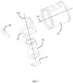
- FIG. 1 is a schematic perspective view of an exhaust gas after-treatment mixing device according to the present application.
- FIG. 2 is another schematic perspective view of FIG. 1 .
- FIG. 3 is a left side view of FIG. 1 .
- FIG. 4 is a right side view of FIG. 1 .
- FIG. 5 is a perspective view with the casing in FIG. 1 removed.
- FIG. 6 is an exploded perspective view of FIG. 5 .
- FIG. 7 is an exploded perspective view of FIG. 6 .
- FIG. 8 is a schematic cross-sectional view taken along a line A-A in FIG. 1 .
- FIG. 9 is a schematic cross-sectional view taken along a line B-B in FIG. 1 .
- the present application discloses an exhaust gas after-treatment mixing device 3 for purifying exhaust gas of an engine.
- the exhaust gas after-treatment mixing device 3 includes a casing 31 , a mixing pipe 32 located in the casing 31 , a partition plate 33 fixed on a periphery of the mixing pipe 32 , a plate 34 located at a bottom of the mixing pipe 32 , and a rectifying plate 38 for partially shielding the mixing pipe 32 .
- the casing 31 is separated by the partition plate 33 to form a first space 301 for communicating with a first after-treatment carrier assembly and a second space 302 for communicating with a second after-treatment carrier assembly.
- the first after-treatment carrier assembly may include a Diesel Oxidation Catalyst (DOC) and a Diesel Particulate Filter (DPF) located downstream of the DOC.
- the second after-treatment carrier assembly includes a Selective Catalytic Reduction (SCR).
- the mixing pipe 32 includes a first pipe portion 321 located in the first space 301 and a second pipe portion 322 located in the second space 302 .
- the first pipe portion 321 is provided with at least two first openings 3211 on two sides of the first pipe portion 321 , respectively.
- the second pipe portion 322 is provided with at least two second openings 3221 on two sides of the second pipe portion 322 , respectively.
- the second openings 3221 communicate with the second space 302 .
- the first openings 3211 are used for airflow to flow in, and the second openings 3221 are used for airflow to flow out, so that a double swirl mixing effect is formed.
- the rectifying plate 38 includes a first shielding plate 381 and a second shielding plate 382 shielding front ends of the first openings 3211 , respectively. As a result, most of the exhaust gas needs to flow bypass the first shielding plate 381 and the second shielding plate 382 before entering the first openings 3211 . This arrangement prevents the exhaust gas from directly rushing into the mixing pipe 32 and reflecting on the pipe wall, which affects the uniformity and stability of the airflow mixing.
- the rectifying plate 38 includes a third curved surface 383 abutting on the first pipe portion 321 .
- the first shielding plate 381 and the second shielding plate 382 are respectively extended oppositely from two sides of the third curved surface 383 .
- the third curved surface 383 is welded to the first pipe portion 321 .
- the first shielding plate 381 is provided with a first arc edge 3811 abutting on an inside of the casing 31
- the second shielding plate 382 is provided with a second arc edge 3821 abutting on an inside of the casing 31 , thereby forming an obstruction to the airflow in order to achieve the rectification effect.
- the casing 31 is of a cylindrical shape and is provided with a first axis 311 .
- the mixing pipe 32 is of a cylindrical shape and is provided with a second axis 323 .
- the first axis 311 intersects the second axis 323 .
- the first axis 311 is perpendicular to the second axis 323 .
- the casing 31 and the mixing pipe 32 may have other shapes, such as an oval shape.
- the partition plate 33 includes a first plate 331 on one side of the mixing pipe 32 , a second plate 332 on the other side of the mixing pipe 32 , and a third plate 333 connecting the first plate 331 and the second plate 332 .
- the third plate 333 is provided with a through hole 334 through which the mixing pipe 32 extends.
- the mixing pipe 32 is arranged vertically.
- the first plate 331 and the second plate 332 both extend vertically but along opposite directions.
- the third plate 333 extends horizontally.
- the partition plate 33 is substantially Z-shaped.
- the first plate 331 is located at a lower left of the mixing pipe 32
- the second plate 332 is located at an upper right of the mixing pipe 32 .
- the first plate 331 is provided with a first curved surface 335 abutting on the second pipe portion 322
- the second plate 332 is provided with a second curved surface 336 abutting on the first pipe portion 321 .
- the plate 34 is located at the bottom of the second pipe portion 322 .
- the plate 34 is provided with an arc-shaped protrusion 341 protruding toward the second pipe portion 322 in order to guide the airflow to flow backwardly.
- the plate 34 can prevent the urea solution from being sprayed directly onto the exhaust pipe, thereby reducing the risk of urea deposit.
- the exhaust gas after-treatment mixing device 3 is provided with an injector mounting seat (not shown) located on the casing 31 and used to install a urea injector for spraying atomized urea solution into the mixing pipe 32 .
- the exhaust gas of the engine passes through the first after-treatment carrier assembly into the first space 301 , the exhaust gas bypasses the first shielding plate 381 and the second shielding plate 382 and then enters the mixing pipe 32 through the first openings 3211 .
- the urea injector sprays urea droplets into the mixing pipe 32 , and the atomized urea droplets is mixed with the exhaust gas of the engine and move downstream, and then enter the second space 302 through the second openings 3221 to reach the second after-treatment carrier assembly.
- the airflow is better reversed (for example, flow upstream) to form a double swirl flow. In this way, the distance and time of urea evaporation are increased by the swirl flow, the uniformity of airflow mixing is improved and the risk of urea deposit is reduced.
Landscapes
- Chemical & Material Sciences (AREA)
- Chemical Kinetics & Catalysis (AREA)
- Engineering & Computer Science (AREA)
- Health & Medical Sciences (AREA)
- Toxicology (AREA)
- Combustion & Propulsion (AREA)
- Mechanical Engineering (AREA)
- General Engineering & Computer Science (AREA)
- Exhaust Gas After Treatment (AREA)
Abstract
Description
Claims (16)
Applications Claiming Priority (3)
| Application Number | Priority Date | Filing Date | Title |
|---|---|---|---|
| CN201710851869.0A CN107575287B (en) | 2017-09-19 | 2017-09-19 | Exhaust aftertreatment mixing device |
| CN201710851869.0 | 2017-09-19 | ||
| PCT/CN2018/092996 WO2019056823A1 (en) | 2017-09-19 | 2018-06-27 | Tail gas post-treatment mixing device |
Related Parent Applications (2)
| Application Number | Title | Priority Date | Filing Date |
|---|---|---|---|
| PCT/CN2017/092996 A-371-Of-International WO2018049908A1 (en) | 2016-09-19 | 2017-07-14 | Web page generation method and device |
| PCT/CN2018/092996 A-371-Of-International WO2019056823A1 (en) | 2017-09-19 | 2018-06-27 | Tail gas post-treatment mixing device |
Related Child Applications (1)
| Application Number | Title | Priority Date | Filing Date |
|---|---|---|---|
| US17/526,692 Continuation US11486290B2 (en) | 2017-09-19 | 2021-11-15 | Exhaust gas after-treatment mixing device |
Publications (2)
| Publication Number | Publication Date |
|---|---|
| US20200217233A1 US20200217233A1 (en) | 2020-07-09 |
| US11208933B2 true US11208933B2 (en) | 2021-12-28 |
Family
ID=61033335
Family Applications (2)
| Application Number | Title | Priority Date | Filing Date |
|---|---|---|---|
| US16/647,481 Active US11208933B2 (en) | 2017-09-19 | 2018-06-27 | Exhaust gas after-treatment mixing device |
| US17/526,692 Active US11486290B2 (en) | 2017-09-19 | 2021-11-15 | Exhaust gas after-treatment mixing device |
Family Applications After (1)
| Application Number | Title | Priority Date | Filing Date |
|---|---|---|---|
| US17/526,692 Active US11486290B2 (en) | 2017-09-19 | 2021-11-15 | Exhaust gas after-treatment mixing device |
Country Status (3)
| Country | Link |
|---|---|
| US (2) | US11208933B2 (en) |
| CN (2) | CN108915831B (en) |
| WO (1) | WO2019056823A1 (en) |
Cited By (2)
| Publication number | Priority date | Publication date | Assignee | Title |
|---|---|---|---|---|
| US20220074336A1 (en) * | 2017-09-19 | 2022-03-10 | Tenneco (Suzhou) Emission System Co., Ltd. | Exhaust gas after-treatment mixing device |
| US20230096559A1 (en) * | 2021-09-24 | 2023-03-30 | Faurecia Emission Control Technologies (Shanghai) Co., Ltd | Mixer and Exhaust System |
Families Citing this family (12)
| Publication number | Priority date | Publication date | Assignee | Title |
|---|---|---|---|---|
| CN110056414A (en) * | 2018-01-19 | 2019-07-26 | 天纳克(苏州)排放系统有限公司 | Tail-gas after treatment apparatus |
| CN108757109A (en) * | 2018-07-11 | 2018-11-06 | 天纳克(苏州)排放系统有限公司 | U-shaped exhaust gas post-treatment device |
| DE102018119578A1 (en) * | 2018-08-13 | 2020-02-13 | Eberspächer Exhaust Technology GmbH & Co. KG | mixer |
| CN109339913B (en) * | 2018-11-19 | 2023-10-20 | 南京朗森自动化设备有限公司 | Self-adaptive urea mixer |
| US10967329B2 (en) * | 2019-02-26 | 2021-04-06 | Faurecia Emissions Control Technologies, Usa, Llc | Automotive exhaust aftertreatment system having a swirl-back mixer |
| IT201900006064A1 (en) * | 2019-04-18 | 2020-10-18 | Magneti Marelli Spa | EXHAUST GAS TREATMENT DEVICE FOR AN EXHAUST SYSTEM OF AN INTERNAL COMBUSTION ENGINE |
| CN110792497A (en) * | 2019-10-08 | 2020-02-14 | 一汽解放汽车有限公司 | U type aftertreatment structure |
| CN112112718A (en) * | 2020-09-30 | 2020-12-22 | 无锡亿利环保科技有限公司 | Mixers for exhaust aftertreatment systems |
| CN114458425A (en) * | 2020-11-09 | 2022-05-10 | 佛吉亚排气控制技术开发(上海)有限公司 | Mixer, exhaust system and mixing method |
| US11585255B2 (en) * | 2020-11-23 | 2023-02-21 | Faurecia Emissions Control Technologies, Usa, Llc | Crowned inlet baffle for high efficiency mixer |
| CN115013128B (en) * | 2022-08-09 | 2023-03-21 | 潍柴动力股份有限公司 | SCR mixer and SCR system |
| CN115807707A (en) * | 2023-01-09 | 2023-03-17 | 北方稀土华凯高科技河北有限公司 | Swirl cover mixer for urea injection mixing of diesel engine |
Citations (27)
| Publication number | Priority date | Publication date | Assignee | Title |
|---|---|---|---|---|
| US4909635A (en) | 1988-01-05 | 1990-03-20 | Societe Anonyme Dite: Alsthom | Static device for homogenizing a flowing fluid |
| DE9113807U1 (en) | 1991-11-06 | 1991-12-19 | Filterwerk Mann & Hummel Gmbh, 7140 Ludwigsburg | Air filter for an internal combustion engine |
| JP2006077576A (en) | 2004-09-07 | 2006-03-23 | Meidensha Corp | Denitration reactor |
| US20100005790A1 (en) * | 2008-07-09 | 2010-01-14 | Xiaogang Zhang | Selective Catalytic Reduction (SCR) Catalyst Injection Systems |
| EP2168672A1 (en) | 2008-09-24 | 2010-03-31 | Emcon Technologies UK Limited | Mixing device |
| WO2012044233A1 (en) | 2010-09-30 | 2012-04-05 | Scania Cv Ab | Arrangement for introducing a liquid medium into exhaust gases from a combustion engine |
| JP5090890B2 (en) | 2007-12-21 | 2012-12-05 | 三菱ふそうトラック・バス株式会社 | Engine exhaust purification system |
| US8397495B2 (en) * | 2008-06-26 | 2013-03-19 | Tenneco Automotive Operating Company Inc. | Exhaust gas additive/treatment system and mixer for use therein |
| DE102012216676A1 (en) | 2012-09-18 | 2014-03-20 | Robert Bosch Gmbh | Exhaust aftertreatment device for internal combustion engine, has baffle plate comprising jet impact surface that impinges liquid upon actuation of injection valve, where surface tapers in flow direction of exhaust gas in exhaust passage |
| CN204877615U (en) | 2015-08-21 | 2015-12-16 | 天纳克(苏州)排放系统有限公司 | Exhaust treatment appts |
| US9352276B2 (en) | 2013-05-07 | 2016-05-31 | Tenneco Automotive Operating Company Inc. | Exhaust mixing device |
| WO2016111701A1 (en) | 2015-01-09 | 2016-07-14 | Cummins Emission Solutions, Inc. | Selective catalytic reduction with integrated decomposition chamber with exhaust flow swirl generating design |
| US20160215673A1 (en) * | 2015-01-22 | 2016-07-28 | Tenneco Automotive Operating Company Inc. | Exhaust Aftertreatment System Having Mixer Assembly |
| CN106014560A (en) | 2016-06-01 | 2016-10-12 | 佛吉亚排气控制技术开发(上海)有限公司 | Mixer used for mixed exhaust and treatment fluid and vehicle exhaust post-treatment device |
| CN205714373U (en) | 2016-06-13 | 2016-11-23 | 天纳克(苏州)排放系统有限公司 | Exhaust aftertreatment mixing arrangement |
| CN106246303A (en) | 2016-10-12 | 2016-12-21 | 天纳克(苏州)排放系统有限公司 | Tail-gas after treatment apparatus |
| CN106523091A (en) | 2016-10-24 | 2017-03-22 | 无锡威孚力达催化净化器有限责任公司 | Page window type cyclone urea mixing device |
| CN206129367U (en) | 2016-10-12 | 2017-04-26 | 天纳克(苏州)排放系统有限公司 | Exhaust aftertreatment device |
| CN106640301A (en) * | 2017-02-22 | 2017-05-10 | 天纳克(苏州)排放系统有限公司 | Tail gas post-treatment device |
| CN206487537U (en) | 2017-02-22 | 2017-09-12 | 天纳克(苏州)排放系统有限公司 | Tail-gas after treatment apparatus |
| CN107165704A (en) * | 2017-07-27 | 2017-09-15 | 天纳克(苏州)排放系统有限公司 | Engine exhaust aftertreatment mixing device and its aftertreatment device and application |
| CN107559078A (en) | 2017-09-29 | 2018-01-09 | 天纳克汽富晟(长春)汽车零部件有限公司 | Tail-gas after treatment apparatus |
| CN107575287A (en) | 2017-09-19 | 2018-01-12 | 天纳克(苏州)排放系统有限公司 | Exhaust gas post-treatment mixing device |
| US20180066559A1 (en) | 2015-03-09 | 2018-03-08 | Tenneco Gmbh | Mixing device |
| CN207178013U (en) | 2017-09-19 | 2018-04-03 | 天纳克(苏州)排放系统有限公司 | Exhaust aftertreatment mixing arrangement |
| CN207526559U (en) | 2017-09-29 | 2018-06-22 | 天纳克一汽富晟(长春)汽车零部件有限公司 | Tail-gas after treatment apparatus |
| US20180306083A1 (en) * | 2017-04-25 | 2018-10-25 | Tenneco Automotive Operating Company Inc. | Counter-swirl mixer |
Family Cites Families (1)
| Publication number | Priority date | Publication date | Assignee | Title |
|---|---|---|---|---|
| DE112017007988T5 (en) * | 2017-09-01 | 2020-06-04 | Faurecia Emissions Control Technologies, Usa, Llc | COMPACT MIXER WITH FLOW Diverter |
-
2017
- 2017-09-19 CN CN201810775568.9A patent/CN108915831B/en active Active
- 2017-09-19 CN CN201710851869.0A patent/CN107575287B/en active Active
-
2018
- 2018-06-27 WO PCT/CN2018/092996 patent/WO2019056823A1/en not_active Ceased
- 2018-06-27 US US16/647,481 patent/US11208933B2/en active Active
-
2021
- 2021-11-15 US US17/526,692 patent/US11486290B2/en active Active
Patent Citations (31)
| Publication number | Priority date | Publication date | Assignee | Title |
|---|---|---|---|---|
| US4909635A (en) | 1988-01-05 | 1990-03-20 | Societe Anonyme Dite: Alsthom | Static device for homogenizing a flowing fluid |
| DE9113807U1 (en) | 1991-11-06 | 1991-12-19 | Filterwerk Mann & Hummel Gmbh, 7140 Ludwigsburg | Air filter for an internal combustion engine |
| JP2006077576A (en) | 2004-09-07 | 2006-03-23 | Meidensha Corp | Denitration reactor |
| JP5090890B2 (en) | 2007-12-21 | 2012-12-05 | 三菱ふそうトラック・バス株式会社 | Engine exhaust purification system |
| US8397495B2 (en) * | 2008-06-26 | 2013-03-19 | Tenneco Automotive Operating Company Inc. | Exhaust gas additive/treatment system and mixer for use therein |
| US20100005790A1 (en) * | 2008-07-09 | 2010-01-14 | Xiaogang Zhang | Selective Catalytic Reduction (SCR) Catalyst Injection Systems |
| US8033104B2 (en) | 2008-07-09 | 2011-10-11 | Ford Global Technologies, Llc | Selective catalytic reduction (SCR) catalyst injection systems |
| CN201551965U (en) | 2008-07-09 | 2010-08-18 | 福特全球技术公司 | Selective Catalytic Reduction Catalyst Injection System |
| EP2168672A1 (en) | 2008-09-24 | 2010-03-31 | Emcon Technologies UK Limited | Mixing device |
| WO2012044233A1 (en) | 2010-09-30 | 2012-04-05 | Scania Cv Ab | Arrangement for introducing a liquid medium into exhaust gases from a combustion engine |
| DE102012216676A1 (en) | 2012-09-18 | 2014-03-20 | Robert Bosch Gmbh | Exhaust aftertreatment device for internal combustion engine, has baffle plate comprising jet impact surface that impinges liquid upon actuation of injection valve, where surface tapers in flow direction of exhaust gas in exhaust passage |
| US9352276B2 (en) | 2013-05-07 | 2016-05-31 | Tenneco Automotive Operating Company Inc. | Exhaust mixing device |
| WO2016111701A1 (en) | 2015-01-09 | 2016-07-14 | Cummins Emission Solutions, Inc. | Selective catalytic reduction with integrated decomposition chamber with exhaust flow swirl generating design |
| US20160215673A1 (en) * | 2015-01-22 | 2016-07-28 | Tenneco Automotive Operating Company Inc. | Exhaust Aftertreatment System Having Mixer Assembly |
| US9784163B2 (en) | 2015-01-22 | 2017-10-10 | Tenneco Automotive Operating Company Inc. | Exhaust aftertreatment system having mixer assembly |
| US20190211732A1 (en) | 2015-03-09 | 2019-07-11 | Tenneco Gmbh | Mixing Device |
| US20180066559A1 (en) | 2015-03-09 | 2018-03-08 | Tenneco Gmbh | Mixing device |
| CN204877615U (en) | 2015-08-21 | 2015-12-16 | 天纳克(苏州)排放系统有限公司 | Exhaust treatment appts |
| CN106014560A (en) | 2016-06-01 | 2016-10-12 | 佛吉亚排气控制技术开发(上海)有限公司 | Mixer used for mixed exhaust and treatment fluid and vehicle exhaust post-treatment device |
| CN205714373U (en) | 2016-06-13 | 2016-11-23 | 天纳克(苏州)排放系统有限公司 | Exhaust aftertreatment mixing arrangement |
| CN106246303A (en) | 2016-10-12 | 2016-12-21 | 天纳克(苏州)排放系统有限公司 | Tail-gas after treatment apparatus |
| CN206129367U (en) | 2016-10-12 | 2017-04-26 | 天纳克(苏州)排放系统有限公司 | Exhaust aftertreatment device |
| CN106523091A (en) | 2016-10-24 | 2017-03-22 | 无锡威孚力达催化净化器有限责任公司 | Page window type cyclone urea mixing device |
| CN206487537U (en) | 2017-02-22 | 2017-09-12 | 天纳克(苏州)排放系统有限公司 | Tail-gas after treatment apparatus |
| CN106640301A (en) * | 2017-02-22 | 2017-05-10 | 天纳克(苏州)排放系统有限公司 | Tail gas post-treatment device |
| US20180306083A1 (en) * | 2017-04-25 | 2018-10-25 | Tenneco Automotive Operating Company Inc. | Counter-swirl mixer |
| CN107165704A (en) * | 2017-07-27 | 2017-09-15 | 天纳克(苏州)排放系统有限公司 | Engine exhaust aftertreatment mixing device and its aftertreatment device and application |
| CN107575287A (en) | 2017-09-19 | 2018-01-12 | 天纳克(苏州)排放系统有限公司 | Exhaust gas post-treatment mixing device |
| CN207178013U (en) | 2017-09-19 | 2018-04-03 | 天纳克(苏州)排放系统有限公司 | Exhaust aftertreatment mixing arrangement |
| CN107559078A (en) | 2017-09-29 | 2018-01-09 | 天纳克汽富晟(长春)汽车零部件有限公司 | Tail-gas after treatment apparatus |
| CN207526559U (en) | 2017-09-29 | 2018-06-22 | 天纳克一汽富晟(长春)汽车零部件有限公司 | Tail-gas after treatment apparatus |
Cited By (4)
| Publication number | Priority date | Publication date | Assignee | Title |
|---|---|---|---|---|
| US20220074336A1 (en) * | 2017-09-19 | 2022-03-10 | Tenneco (Suzhou) Emission System Co., Ltd. | Exhaust gas after-treatment mixing device |
| US11486290B2 (en) * | 2017-09-19 | 2022-11-01 | Tenneco (Suzhou) Emission System Co., Ltd. | Exhaust gas after-treatment mixing device |
| US20230096559A1 (en) * | 2021-09-24 | 2023-03-30 | Faurecia Emission Control Technologies (Shanghai) Co., Ltd | Mixer and Exhaust System |
| US11913369B2 (en) * | 2021-09-24 | 2024-02-27 | Faurecia Emission Control Technologies (Shanghai) Co., Ltd | Mixer and exhaust system |
Also Published As
| Publication number | Publication date |
|---|---|
| WO2019056823A1 (en) | 2019-03-28 |
| US20200217233A1 (en) | 2020-07-09 |
| CN108915831A (en) | 2018-11-30 |
| CN107575287B (en) | 2019-07-23 |
| US11486290B2 (en) | 2022-11-01 |
| CN108915831B (en) | 2021-04-02 |
| CN107575287A (en) | 2018-01-12 |
| US20220074336A1 (en) | 2022-03-10 |
Similar Documents
| Publication | Publication Date | Title |
|---|---|---|
| US11486290B2 (en) | Exhaust gas after-treatment mixing device | |
| US10704448B2 (en) | Exhaust gas after-treatment mixing device and package therefor | |
| WO2018006718A1 (en) | Tail gas aftertreatment device | |
| CN106640301B (en) | Exhaust after-treatment device | |
| CN110080861B (en) | Exhaust gas aftertreatment device | |
| WO2017215458A1 (en) | Exhaust gas postprocessing apparatus | |
| WO2019144600A1 (en) | Exhaust after-treatment device | |
| CN202028346U (en) | Static mixer for urea selective catalytic reduction device of diesel engine | |
| CN116658278A (en) | A post-processing package | |
| CN107514305B (en) | Tail gas aftertreatment device | |
| CN107559078A (en) | Tail-gas after treatment apparatus | |
| CN107869376B (en) | Hybrid components | |
| WO2019140865A1 (en) | Exhaust gas aftertreatment device | |
| US11187132B2 (en) | Exhaust gas after-treatment mixing device | |
| CN111425284B (en) | Exhaust gas after-treatment mixing device and exhaust gas after-treatment device | |
| WO2019140892A1 (en) | Exhaust aftertreatment apparatus | |
| CN108757109A (en) | U-shaped exhaust gas post-treatment device | |
| CN111764989A (en) | Efficient post-processing packaged SCR mixer system and processing method thereof | |
| CN212027907U (en) | Exhaust aftertreatment mixing arrangement and exhaust aftertreatment device | |
| WO2019144599A1 (en) | Exhaust inlet pipe and exhaust post-treatment apparatus thereof | |
| WO2019128164A1 (en) | Mixing device for exhaust post-processing, and package therefor | |
| CN108757128A (en) | Mixing chamber component | |
| CN110056412B (en) | Exhaust gas aftertreatment device | |
| CN210370872U (en) | Exhaust aftertreatment blender | |
| CN208416654U (en) | U-shaped exhaust gas post-treatment device |
Legal Events
| Date | Code | Title | Description |
|---|---|---|---|
| AS | Assignment |
Owner name: TENNECO (SUZHOU) EMISSION SYSTEM CO., LTD., CHINA Free format text: ASSIGNMENT OF ASSIGNORS INTEREST;ASSIGNOR:WANG, CONG;REEL/FRAME:052166/0093 Effective date: 20191225 |
|
| FEPP | Fee payment procedure |
Free format text: ENTITY STATUS SET TO UNDISCOUNTED (ORIGINAL EVENT CODE: BIG.); ENTITY STATUS OF PATENT OWNER: LARGE ENTITY |
|
| STPP | Information on status: patent application and granting procedure in general |
Free format text: DOCKETED NEW CASE - READY FOR EXAMINATION |
|
| STPP | Information on status: patent application and granting procedure in general |
Free format text: NON FINAL ACTION MAILED |
|
| STPP | Information on status: patent application and granting procedure in general |
Free format text: RESPONSE TO NON-FINAL OFFICE ACTION ENTERED AND FORWARDED TO EXAMINER |
|
| STPP | Information on status: patent application and granting procedure in general |
Free format text: NOTICE OF ALLOWANCE MAILED -- APPLICATION RECEIVED IN OFFICE OF PUBLICATIONS |
|
| STPP | Information on status: patent application and granting procedure in general |
Free format text: PUBLICATIONS -- ISSUE FEE PAYMENT VERIFIED |
|
| STCF | Information on status: patent grant |
Free format text: PATENTED CASE |
|
| MAFP | Maintenance fee payment |
Free format text: PAYMENT OF MAINTENANCE FEE, 4TH YEAR, LARGE ENTITY (ORIGINAL EVENT CODE: M1551); ENTITY STATUS OF PATENT OWNER: LARGE ENTITY Year of fee payment: 4 |