US11201984B2 - Computer-readable storage medium and information processing apparatus - Google Patents
Computer-readable storage medium and information processing apparatus Download PDFInfo
- Publication number
- US11201984B2 US11201984B2 US16/983,109 US202016983109A US11201984B2 US 11201984 B2 US11201984 B2 US 11201984B2 US 202016983109 A US202016983109 A US 202016983109A US 11201984 B2 US11201984 B2 US 11201984B2
- Authority
- US
- United States
- Prior art keywords
- image
- partial
- partial images
- processing apparatus
- information processing
- Prior art date
- Legal status (The legal status is an assumption and is not a legal conclusion. Google has not performed a legal analysis and makes no representation as to the accuracy of the status listed.)
- Active
Links
- 230000010365 information processing Effects 0.000 title claims abstract description 76
- 239000002131 composite material Substances 0.000 claims abstract description 133
- 238000000034 method Methods 0.000 claims description 46
- 238000004891 communication Methods 0.000 claims description 35
- 230000004044 response Effects 0.000 claims description 8
- 238000013500 data storage Methods 0.000 description 15
- 238000003384 imaging method Methods 0.000 description 6
- 230000014509 gene expression Effects 0.000 description 5
- 238000007639 printing Methods 0.000 description 3
- 230000012447 hatching Effects 0.000 description 2
- 239000000853 adhesive Substances 0.000 description 1
- 230000001070 adhesive effect Effects 0.000 description 1
- 238000003491 array Methods 0.000 description 1
- 238000006243 chemical reaction Methods 0.000 description 1
- 238000010586 diagram Methods 0.000 description 1
- 238000007641 inkjet printing Methods 0.000 description 1
- 239000004973 liquid crystal related substance Substances 0.000 description 1
- 238000010023 transfer printing Methods 0.000 description 1
Images


Classifications
-
- H—ELECTRICITY
- H04—ELECTRIC COMMUNICATION TECHNIQUE
- H04N—PICTORIAL COMMUNICATION, e.g. TELEVISION
- H04N1/00—Scanning, transmission or reproduction of documents or the like, e.g. facsimile transmission; Details thereof
- H04N1/0035—User-machine interface; Control console
- H04N1/00405—Output means
- H04N1/00408—Display of information to the user, e.g. menus
- H04N1/0044—Display of information to the user, e.g. menus for image preview or review, e.g. to help the user position a sheet
- H04N1/00442—Simultaneous viewing of a plurality of images, e.g. using a mosaic display arrangement of thumbnails
- H04N1/00456—Simultaneous viewing of a plurality of images, e.g. using a mosaic display arrangement of thumbnails for layout preview, e.g. page layout
-
- H—ELECTRICITY
- H04—ELECTRIC COMMUNICATION TECHNIQUE
- H04N—PICTORIAL COMMUNICATION, e.g. TELEVISION
- H04N1/00—Scanning, transmission or reproduction of documents or the like, e.g. facsimile transmission; Details thereof
- H04N1/00567—Handling of original or reproduction media, e.g. cutting, separating, stacking
- H04N1/0057—Conveying sheets before or after scanning
-
- H—ELECTRICITY
- H04—ELECTRIC COMMUNICATION TECHNIQUE
- H04N—PICTORIAL COMMUNICATION, e.g. TELEVISION
- H04N1/00—Scanning, transmission or reproduction of documents or the like, e.g. facsimile transmission; Details thereof
- H04N1/00681—Detecting the presence, position or size of a sheet or correcting its position before scanning
- H04N1/00684—Object of the detection
- H04N1/00708—Size or dimensions
- H04N1/0071—Width
-
- H—ELECTRICITY
- H04—ELECTRIC COMMUNICATION TECHNIQUE
- H04N—PICTORIAL COMMUNICATION, e.g. TELEVISION
- H04N1/00—Scanning, transmission or reproduction of documents or the like, e.g. facsimile transmission; Details thereof
- H04N1/387—Composing, repositioning or otherwise geometrically modifying originals
- H04N1/3876—Recombination of partial images to recreate the original image
-
- H—ELECTRICITY
- H04—ELECTRIC COMMUNICATION TECHNIQUE
- H04N—PICTORIAL COMMUNICATION, e.g. TELEVISION
- H04N1/00—Scanning, transmission or reproduction of documents or the like, e.g. facsimile transmission; Details thereof
- H04N1/387—Composing, repositioning or otherwise geometrically modifying originals
Definitions
- An aspect of the present disclosure is related to a computer-readable storage medium and an information processing apparatus.
- a print-controlling apparatus capable of printing posters is known.
- the print-controlling apparatus may divide the original image into a plurality of smaller partial images and place the partial images together. Sizes of the partial images may be determined based on a size of a sheet, on which the partial images are to be printed.
- the print-controlling apparatus may divide the original image into the plurality of smaller parts along a single direction, e.g., a widthwise direction, of the original image, and print the smaller parts on the sheet.
- a single direction e.g., a widthwise direction
- the parts of the sheet, on which the partial image are printed may contain blank areas, in which no image is printed.
- the present disclosure is advantageous in that a computer readable storage medium storing computer readable instructions, which may control an information processing apparatus to efficiently generate partial images, and an information processing apparatus are provided.
- a non-transitory computer-readable storage medium storing computer-readable instructions for an information processing apparatus.
- the computer-readable instructions when executed by a processor of the information processing apparatus, cause the information processing apparatus to perform obtaining a width of an image-formable area, in which an image is formable on a sheet, the image-formable area being in a rectangular shape having a first side extending along a first direction and a second side extending along a second direction, the second direction intersecting orthogonally with the first direction, the width being a size of the first side, and object image data composing an object image containing an object, the object image having a size larger than the width in a widthwise direction corresponding to the first direction and in a lengthwise direction corresponding to the second direction; defining a first partial image and a second partial image in the object image, the first partial image and the second partial image each having a rectangular shape, the first partial image having a third side, the third side extending along the widthwise direction, a size
- a non-transitory computer-readable storage medium storing computer-readable instructions for an information processing apparatus.
- the computer-readable instructions when executed by a processor of the information processing apparatus, cause the information processing apparatus to perform obtaining a width of an image-formable area, in which an image is formable on a sheet, the image-formable area being in a rectangular shape having a first side extending along a first direction and a second side extending along a second direction, the second direction intersecting orthogonally with the first direction, the width being a size of the first side, and object image data composing an object image containing an object, the object image having a size larger than the width in a widthwise direction corresponding to the first direction and in a lengthwise direction corresponding to the second direction; defining a plurality of first partial images in the object image, each of the plurality of first partial images having a rectangular shape and having a third side, the third side extending along the widthwise direction, a size of the third side being at most equal
- an information processing apparatus having a communication interface and a controller
- the controller is configured to obtain a width of an image-formable area, in which an image is formable on a sheet, the image-formable area being in a rectangular shape having a first side extending along a first direction and a second side extending along a second direction, the second direction intersecting orthogonally with the first direction, the width being a size of the first side, and object image data composing an object image containing an object, the object image having a size larger than the width in a widthwise direction corresponding to the first direction and in a lengthwise direction corresponding to the second direction; define a first partial image and a second partial image in the object image, the first partial image and the second partial image each having a rectangular shape, the first partial image having a third side, the third side extending along the widthwise direction, a size of the third side being at most equal to the width, the second partial image having a fourth side, the fourth side
- an information processing apparatus having a communication interface and a controller.
- the controller is configured to obtain a width of an image-formable area, in which an image is formable on a sheet, the image-formable area being in a rectangular shape having a first side extending along a first direction and a second side extending along a second direction, the second direction intersecting orthogonally with the first direction, the width being a size of the first side, and object image data composing an object image containing an object, the object image having a size larger than the width in a widthwise direction corresponding to the first direction and in a lengthwise direction corresponding to the second direction; define a plurality of first partial images in the object image, each of the plurality of first partial images having a rectangular shape and having a third side, the third side extending along the widthwise direction, a size of the third side being at most equal to the width; define a plurality of second partial images in the object image, each of the plurality of second partial images having a
- FIG. 1 is a block diagram to illustrate configurations of an information processing apparatus 100 and an image forming apparatus 200 according to embodiments of the present disclosure.
- FIG. 2A is an illustrative view of an internal configuration of the image forming apparatus 200 according to the embodiments of the present disclosure.
- FIG. 2B is an illustrative view of an object image based on a unit of object image data 401 according to the embodiments of the present disclosure.
- FIG. 2C is an illustrative view of data structures of the unit of object image data 400 and a unit of composite image data 410 according to the embodiments of the present disclosure.
- FIGS. 3A-3C are flowcharts to illustrate flows of steps to be executed by an editor program 29 in the information processing apparatus 100 according to a first embodiment of the present disclosure.
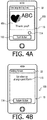
- FIGS. 4A-4C are illustrative views of an object-image displaying screen 32 , a setting screen 33 , and a preview screen 34 , respectively, to be displayed in a display 15 in the information processing apparatus 100 according to the first embodiment of the present disclosure.
- FIG. 5A is an illustrative view of an arrangement of first through third partial images 406 A- 406 C composed of the unit of object image data 401 to be arranged by an editor program 29 according to the first embodiment of the present disclosure.
- FIG. 5B is an illustrative view of a composite image 411 to be generated by the editor program 29 according to the first embodiment of the present disclosure.
- FIG. 5C is an illustrative view of another arrangement of the first through third partial images 406 A- 406 C composed of the unit of object image data 401 to be arranged by the editor program according to the first embodiment of the present disclosure.
- FIG. 5D is an illustrative view of another composite image 411 to be generated by the editor program 29 according to the first embodiment of the present disclosure.
- FIG. 6 is an illustrative view of a guidance screen 420 to be displayed in the display 15 in the information processing apparatus 100 according to the first embodiment of the present disclosure.
- FIG. 7A is an illustrative view of another arrangement of first through third partial images 406 D- 406 F composed of the unit of object image data 401 to be arranged by the editor program according to the first embodiment of the present disclosure.
- FIG. 7B is an illustrative view of another composite image 411 to be generated by the editor program 29 according to the first embodiment of the present disclosure.
- FIG. 8A is a flowchart to illustrate flows of steps to be executed by the editor program 29 in the information processing apparatus 100 according to a second embodiment of the present disclosure.
- FIGS. 8B-8C are first and second modified examples of the flows of the steps to be executed by the editor program 29 in the information processing apparatus 100 according to the second embodiment of the present disclosure.
- FIGS. 9A-9B are illustrative views of an object-image displaying screen 32 A and a preview screen 34 A to be displayed in the display 15 , respectively, in the information processing apparatus 100 according to the second embodiment of the present disclosure.
- FIG. 9C is an illustrative view of arrangement of first partial images 407 A composed of the unit of object image data 401 to be arranged by the editor program according to the second embodiment of the present disclosure.
- FIG. 9D is an illustrative view of a composite image 431 A to be generated by the editor program 29 according to the second embodiment of the present disclosure.
- FIG. 10A is an illustrative view of arrangement of second partial images 407 B composed of the unit of object image data 401 to be arranged by the editor program according to the second embodiment of the present disclosure.
- FIG. 10B is an illustrative view of a composite image 431 B to be generated by the editor program 29 according to the second embodiment of the present disclosure.
- FIG. 10C is a third modified example of the flows of the steps to be executed by the editor program 29 in the information processing apparatus 100 according to the second embodiment of the present disclosure.
- FIG. 11A-11B are illustrative views of processes to the first partial images 407 A and the second partial images 407 B to be executed by the editor program 29 in the information processing apparatus 100 in the third modified example of the second embodiment of the present disclosure.
- an information processing apparatus 100 and an image forming apparatus 200 may communicate with each other through a communication network 300 .
- the information processing apparatus 100 includes, for example, a smartphone, a tablet terminal, and a personal computer.
- the information processing apparatus 100 may generate imaging data, which composes an image to be formed on a sheet in the image forming apparatus 200 .
- the imaging data may be transmitted from the information processing apparatus 100 to the image forming apparatus 200 through the communication network 300 .
- the communication network 300 may be, for example, wired LAN, wireless LAN, and a combination of the wired and wireless LANs.
- the information processing apparatus 100 and the image forming apparatus 200 may not necessarily communicate through LAN(s), but the information processing apparatus 100 and the image forming apparatus 200 may be connected to communicate with each other through, for example, a USB cable.
- the image forming apparatus 200 may include, for example, a label printer capable of forming an image on a sheet 28 based on the imaging data received through, for example, the communication network 300 , and discharge the sheet 28 with the image formed thereon outside.
- a label printer capable of forming an image on a sheet 28 based on the imaging data received through, for example, the communication network 300 , and discharge the sheet 28 with the image formed thereon outside.
- the information processing apparatus 100 includes, but not limited to, a CPU 11 , a memory 12 , a communication interface (I/F) 13 , a user interface (I/F) 14 , a display 15 , and a communication bus 16 .
- the components in the information processing apparatus 100 are connected to communicate with one another through the communication bus 16 .
- the CPU 11 may control overall actions and processes in the image forming apparatus 100 .
- the CPU 11 may, in response to operations input by a user through the user I/F 14 , read and run programs stored in the memory 12 .
- the memory 12 includes memory media such as ROM, RAM, and EEPROM, and a buffer in the CPU 11 .
- the memory 12 may include any computer-readable storage medium, which is a non-transitory medium.
- the non-transitory medium may include a tangible medium.
- electrical signals conveying a program that is downloadable through the Internet from, for example, a server (not shown), may form a computer-readable signal medium but may not form a non-transitory computer-readable storage medium.
- the memory 12 has a program storage area 12 A and a data storage area 12 B.
- the program storage area 12 A may store programs, including an OS 28 and an editor program 29 .
- the OS 28 is a basic program in the information processing apparatus 100 .
- the program storage area 12 A may further store a driver 210 .
- the editor program 29 may, in response to operations by a user input through the user I/F 14 , generate imaging data. In order to generate the imaging data, the editor program 29 may input and output various kinds of information and data in and from the OS 28 .
- the editor program 29 may include a single program and a collection of program modules. The editor program 29 will be described further below.
- the data storage area 12 B may store various kinds of information and data to be used and processed by the editor program 29 and the OS 28 .
- the communication I/F 13 may include, for example, a communication interface for Wi-Fi (registered trademark).
- Wi-Fi registered trademark
- the communication I/F 13 is in compliance with the USB standard.
- the communication I/F 13 may transmit the information and the data output from the OS 28 to the image forming apparatus 200 through the communication network 300 .
- the communication I/F 13 may output the information and the data received from the image forming apparatus 200 to the OS 28 .
- the user I/F 14 is an interface, through which the operations by the user may be input.
- the user I/F 14 may include a touch sensor and hardware buttons (not shown).
- the display 15 includes, for example, a liquid crystal display and an organic EL display, and has a displaying surface, on which screens for the ongoing operations may be displayed.
- the screens may contain objects including, for example, text, image, icon, and text box.
- the user's operations may include operations to designate the object(s) by use of an input device or a pointer including the user's finger, a stylus, and a pen, and operations to input text and/or numerical figures in the object(s).
- the image forming apparatus 200 includes, but not limited to, a CPU 21 , a memory 22 , a communication I/F 23 , a cartridge 27 , a conveyer 24 , and a recording head 25 , which are connected with one another through a communication bus 26 .
- the CPU 21 , the memory 22 , and the communication I/F 23 in the image forming apparatus 200 may be in equivalent or similar structures to the CPU 11 , the memory 12 , and the communication I/F 13 , respectively, in the information processing apparatus 100 ; therefore, detailed description of those is herein omitted.
- the memory 22 has a program storage area 22 A and a data storage area 22 B.
- the program storage area 22 A may store programs, including an OS 221 and a controlling program 222 .
- the OS 221 is a basic program in the image forming apparatus 200 .
- the controlling program 222 may execute various kinds of processes and input and output various kinds of information and data in and from the OS 221 .
- the data storage area 12 B may store information and data to be used by the controlling program 222 and the OS 221 .
- the cartridge 27 is attachable to the image forming apparatus 200 .
- the cartridge 27 may include a reeled sheet 28 .
- the sheet 28 may be, for example, an elongated strip of adhesive label.
- the sheet 28 may be unreeled and conveyed outside the cartridge 27 by the conveyer 24 along a lengthwise direction 5 .
- the lengthwise direction 5 is an elongated or extending direction of the sheet 28 and coincides with a conveying direction for the sheet 28 and with a second direction.
- the cartridge 27 includes a memory 27 A (see FIG. 1 ).
- the memory 27 A stores sheet information, which at least includes information concerning a sheet width w 1 .
- the sheet width w 1 is a dimension of the sheet 28 in a widthwise direction 6 and is fixed.
- the widthwise direction 6 may intersect orthogonally with the lengthwise direction 5 and coincides with a first direction.
- the sheet information may not include information concerning a sheet length.
- the conveyer 24 may convey the sheet 28 unreeled from the cartridge 27 to the recording head 25 .
- the recording head 25 may form an image composed of the imaging data on the sheet 28 under the control of the controlling program 222 in one of known printing technics including, for example, inkjet-printing, electro-photographic printing, and thermal-transfer printing.
- the conveyer 24 may eject the sheet 28 with the image formed thereon outside the image forming apparatus 200 .
- the sheet 28 includes, as shown in FIG. 2A , an image-formable area 28 A.
- the image-formable area 28 A may be, for example, an entire range on an image-formable surface of the sheet 28 .
- the image-formable area 28 A is rectangular and has a first side H 1 , which extends along the widthwise direction 6 , and a second side H 2 , which extends along the lengthwise direction 5 .
- a dimension of the first side H 1 is equal to the sheet width w 1 .
- the recording sheet 25 may not be adapted to form an image in the entire range of the image-formable area 28 A. In such a case, as shown in FIG.
- the image-formable area 28 A may include margins 28 B.
- the margin 28 is an area, in which an image may not be formed, within the image-formable area 28 A.
- the margins 28 may be located on ends of the image-formable area 28 A in the widthwise direction 6 .
- processes to be conducted by the CPU 11 of the information processing apparatus 100 in compliance with instructions described in the programs stored in the memory 12 will be explained.
- terms to express the actions in the information processing apparatus 100 such as judging, extracting, selecting, calculating, determining, specifying, obtaining, accepting, controlling, and setting may represent processes conducted by the CPU 11 .
- the processes to be conducted by the CPU 11 may include control over hardware devices by a controller, including the OS 28 , in the information processing apparatus 100 . Meanwhile, an act of obtaining may not necessarily be limited to a result of requesting.
- the CPU 11 may receive data without requesting the data, and the act of receiving may still be expressed as “the CPU 11 obtains the data.”
- a term “data” in the present disclosure may mean a bit string readable by a computer. Data units containing substantially the same contents but in different formats may be regarded as a same data unit, and a term “information” may be regarded similarly.
- Terms for actions of “requesting,” “instructing,” and “commanding” may represent outputting information that composes the request, the instruction, and the command, respectively, to another party. Meanwhile, the information that composes the request, the instruction, and the command may be expressed by terms “request,” “instruction,” and “command,” respectively. Meanwhile, an action by the CPU 11 to store information or data in the data storage area 12 B may be expressed by the term “obtain.”
- processes to be conducted by the CPU 11 in compliance with the commands contained in the programs may be described in simplified or anthropomorphic expressions such as “the CPU 11 conducts the process,” “the editor program 29 conducts the process,” or “the information processing apparatus 100 conducts the process.” Further, input or output of information conducted by the programs through the communication I/F 13 or the user I/F 14 may be described also in simplified or anthropomorphic expressions such “the CPU 11 receives the information,” “the editor program 29 ,” or “the information processing apparatus 100 obtains the information.”
- a process conducted by the CPU 11 to determine, for example, whether information “A” indicates occurrence of an event “B” may be described in an expression such as “the CPU 11 determines occurrence of an event “B” based on information “A.” Further, a process conducted by the CPU 11 to determine, for example, whether information “A” indicates occurrence of an event “B” or “C” may be described in an expression such as “the CPU 11 determines whether an event “B” or “C” occurs.
- data and information may be considered to have common meanings in a sense that they both may denote a bit or a string of bits that may be processed by a computer.
- data and information may be distinguished from each other by meaning(s) of content in the bit or the bit string. That is, while the bit or the bit string in the data may be processed by the computer without considering the meaning of the content thereof, actions of the computer may vary depending on the content of the bit or the bit string in the information.
- Information may be contained in a command, which may be a controlling signal transmitted from the computer to a receiver device to cause the receiver device to act responsively to the information, or the command itself may have the characteristics of information.
- formats of data and information may be converted among a plurality of computers
- the data and the information may be regarded as identical data and information as long as the contents of the data and the information before and after the conversion are maintained unchanged.
- information indicating a quantity “2” may be described as “0x32” in ASCII code in the text format to be stored in one computer and as “10” in the binary format to be stored in another computer.
- data and information may not necessarily be distinctively exclusive to each other but may be occasionally equated with each other.
- data may be temporarily regarded as information, and vice versa.
- data handled in one device may be handled as information in another device, and vice versa.
- information may be extracted from data, and vice versa.
- a phrase “in response to” may mean that once a condition described in a preceding clause including the phrase is met, an action described in a subsequent clause may be performed.
- the action described in the subsequent clause may not necessarily be performed immediately after the condition in the preceding clause is met as long as the action is performed later than the condition being met.
- the editor program 29 obtains a width of the image-formable area 28 A, i.e., the sheet width w 1 .
- the editor program 29 obtains the sheet width w 1 being the sheet information through the communication with the image forming apparatus 200 .
- the editor program 29 may not necessarily obtain the sheet information through the communication with the image forming apparatus 200 .
- the sheet information may be stored in the data storage area 12 B in the information processing apparatus 100 or a server (not shown) connected to the Internet (not shown), the editor program 29 may obtain the sheet information from the data storage area 12 B or the server.
- the sheet information may be stored in the editor program 29 , and the editor program 29 may store the sheet information from the storage thereof.
- the editor program 29 displays an image-selectable screen, which includes a plurality of image icons. Each image icon displayed in the image-selectable screen is associated with a unit of object image data 400 (see FIG. 2C ) correspondingly.
- the editor program 29 may generate or obtain displayable data composing a screen and input the generated or obtained displayable data in the OS 28 to cause the screen to be displayed in the display 15 through the OS 28 .
- a unit of object image data 400 composes an object image 401 , for example, as shown in FIG. 2B .
- the object image 401 is a rectangular image having sides H 11 , H 12 , which extend from an origin point P 0 .
- the sides H 11 , H 12 extend along the first direction 9 and the second direction 8 , respectively.
- the first direction 9 and the second direction 8 coincide with a widthwise direction 9 A and a lengthwise direction 8 A of the object image 401 , respectively.
- the widthwise direction 9 A and the lengthwise direction 8 A coincide with the directions, in which the sides H 11 , H 12 extend from the origin point P 0 , respectively. Lengths of the sides H 11 , H 12 are greater than the sheet width w 1 (see FIG. 2A ).
- the object image 401 includes at least one (1) object 402 .
- the object 402 may represent, for example, a figure or a character string to be arranged over a background 403 and may include, for example, objects 402 A- 402 C.
- the object 402 A may represent a heart
- the object 402 B may represent characters included in a character string “ABD”
- the object 402 C may represent characters and signs included in a character string “Thank you!!”.
- the object image 401 may include, for another example, a picture including a background and a photographed figure.
- a unit of object image data 400 includes size information 404 and a plurality of units of pixel information 405 to compose the object image 401 .
- the size information 404 indicates a size of the object image 401 in the lengthwise direction 8 A.
- Each unit of pixel information 405 includes values for red (R), green (G), blue (B), and brightness in a pixel that constitutes the object image 401 .
- the units of pixel information 405 are arranged in one-dimensional array coinciding with the second direction 8 , or the lengthwise direction 8 A.
- a unit of pixel information 405 for a pixel located at the origin point P 0 is arrayed next to the size information 404 , and units of pixel information 405 for pixels located subsequently in the object image 401 along the second direction 8 or the lengthwise direction 8 A are arrayed in the order of the arrangement in the object image 401 .
- the editor program 29 may receive a user's operation to designate one of the image icons displayed in the display 15 through the user I/F 14 and read the object image data 400 corresponding to the designated one of the image icons from the data storage area 12 B.
- the editor program 29 may generate displayable data, which composes an object-image displaying screen 32 (see FIG. 4A ), based on the object image data 400 having been read.
- the object image data 400 being currently read to be processed may be called as focused image data 400 .
- the editor program 29 controls the display 15 to display the object-image displaying screen 32 based on the generated displayable data.
- the editor program 29 may not necessarily obtain the object image data 400 from the data storage area 12 B.
- the OS 28 may share data stored in the memory 12 with other programs stored in the program storage area 12 A
- the editor program 29 may obtain the object image data 400 designated by another one of the programs through the OS 28 .
- the editor program 29 may create object image data 400 within the data storage area 12 B in response to the user's operations
- the editor program 29 may obtain the created object image data 400 within the data storage area 12 B.
- the object-image displaying screen 32 includes an image resized from the object image 401 composed of the focused image data 400 , a start button 113 , and a setting button 114 .
- the object image 401 composed of the focused image data 400 may be called as a focused object image 401 .
- the start button 113 and the setting button 114 are designative objects that may be designated by the user through the user I/F 14 .
- the start button 113 may be designated by the user's operation to start image forming
- the setting button 117 may be designated by the user's operation to setup the image forming.
- the editor program 29 may further receive the user's operation designating either the start button 113 or the setting button 114 .
- the editor program 29 determines whether the object designated by the user's operation in S 3 was the start button 113 or the setting button 114 . If the start button 113 was designated, the editor program 29 proceeds to S 7 . If the setting button 114 was designated, the editor program 29 proceeds to S 5 and controls the display 15 to display a setting screen 33 (see FIG. 4B ).
- the setting screen 33 includes a reference-designative checkbox 115 and a return button 116 .
- the reference-designative checkbox 115 is a designative object that may be designated by the user to designate the origin point P 0 (see FIG. 2B ) as a reference point for a defining process, which is performed in one of the steps from S 8 through S 15 and from S 16 through S 23 in FIG. 3C .
- a vertex P 3 (see FIG. 2B ) of the focused object image 401 may be designated as the reference point.
- the reference point for the defining process is either one end or the other end of the side H 11 in the widthwise direction 9 A in the focused object image 401 (see FIG. 2B ).
- the defining process will be described with reference to FIGS. 5A-5D in the following paragraphs.
- the information processing apparatus 100 defines a plurality of partial images 406 (see FIGS. 5A and 5C ) in the focused object image 401 .
- the focused object image 401 has four (4) sides, of which lengths are each greater than the sheet width w 1 .
- Each of the plurality of partial images 406 has a side having a predetermined length, which is in a fixed value equal to the sheet width w 1 .
- the predetermined length may be smaller than the sheet width w 1 .
- the information processing apparatus 100 identifies a plurality of units of pixel information 405 (see FIG. 2C ) corresponding to each of the partial images 406 .
- the partial images 406 include a first partial image 406 A and a second partial image 406 B, as shown in FIGS. 5A and 5C , and may further include a third partial image 406 C.
- Each of the first, second, and third partial images 406 A, 406 B, 406 C is one of the partial images 406 , into which the object image 401 is divided by broken lines shown in FIGS. 5A and 5C .
- the partial images 406 may include two (2) first partial images 406 A, three (3) second partial images 406 B, and one (1) third partial image 406 C.
- Each first partial image 406 A has a side H 3 extending along the widthwise direction 9 A.
- a length of the side H 3 is equal to the predetermined length.
- the first partial image 406 A has the same size in the lengthwise direction 8 A as the object image 401 .
- Each second partial image 406 B has a side H 4 extending along the lengthwise direction 8 A.
- a length of the side H 4 is equal to the predetermined length.
- the second partial image 406 B has a size smaller in the widthwise direction 9 A than the predetermined length.
- one of the first partial images 406 A includes the origin point P 0
- one of the second partial images 406 B includes the vertex P 3 (see FIG. 5A ).
- the third partial image 406 C is a remainder of the object image 401 after the first partial images 406 A and the second partial images 406 B are defined and subtracted from the object image 401 .
- the return button 116 is an object to be designated by the user through the user I/F 14 when the user desires to cause the screen of the display 15 to return from the setting screen 33 to the object-image displaying screen 32 .
- the user may, after operating the reference-designative checkbox 115 through the user I/F 14 , operate the return button 116 .
- the editor program 29 may receive the user's operation to the reference-designative checkbox 115 and the return button 116 .
- the editor program 29 obtains reference information, which indicates the reference point for the defining process corresponding to the user's operation to the reference-designative checkbox 115 , and stores the obtained reference information in the data storage area 12 B.
- the reference information includes one of a first status value and a second status value.
- the first status value indicates that the reference point is at the origin point P 0
- the second status value indicates that the reference point is not at the origin point P 0 .
- the editor program 29 returns to S 3 in response to the user's operation to the return button 116 in S 5 and controls the display 15 to once again display the object-image displaying screen 32 .
- the editor program 29 determines whether the reference information indicates the first status value. If the reference information does not indicate the first status value (S 7 : NO), the editor program 29 proceeds to S 16 (see FIG. 3C ). If the reference information indicates the first status value (S 7 : YES), in S 8 , the editor program 29 sets a counter (not shown) at 1 being an initial value. The counter may count consecutive numbers, and a value in the counter, which will hereinafter be called as counter value, indicates an ordinal number, by which the units of pixel information 405 corresponding to one of the first partial images 406 A through the third partial image 406 C are identified in S 8 -S 15 . In other words, the units of pixel information 405 corresponding to each of the partial images 406 are collectively given a counter value indicating an ordinal number.
- the editor program 29 identifies the units of pixel information 405 corresponding to one of the first partial images 406 A that includes the origin point P 0 (see FIG. 5A ) among the entire units of pixel information 405 contained in the focused image data 400 based on the size information 404 and the predetermined length. Further, in S 9 , the editor program 29 stores the identified units of pixel information 405 in the storage area 15 B.
- the identified units of pixel information 405 corresponding to one of the partial images 406 are defined as a set of pixel information 405 . In the following description, the identified units of pixel information 405 corresponding to one of the partial images 406 may be called as a pixel information set 405 .
- the acts by the editor program 29 of defining the pixel information set 405 corresponding to one of the partial images 406 and storing the defined pixel information set 405 in the data storage area 12 B may be described in a more simplified expression such as “the editor program 29 defines a partial image 406 .”
- the editor program 29 assigns a latest counter value to a defined pixel information set 405 A and increments the count value by 1.
- the acts by the editor program 29 of assigning a latest current value to the defined pixel information set 405 and incrementing the count value by 1 may be called as an assigning process.
- the editor program 29 determines whether a size of a first differential image in the widthwise direction 9 A is greater than or equal to the predetermined length preset in the editor program 29 .
- the first differential image is a remainder image in the focused object image 401 after the defined first partial image(s) 406 A is/are subtracted.
- the editor program 29 defines another pixel information set 405 A corresponding to another one of the first partial images 406 A (see FIG. 5A ) among the pixel information units 405 corresponding to the first differential image, in the same manner as S 9 .
- the another one of the first partial images 406 A shares one of the sides extending along the lengthwise direction 8 A with the one of the first partial image 406 A, of which pixel information set 405 was defined in the immediate past.
- the editor program 29 conducts the assigning process and returns to S 10 .
- the editor program 29 defines the units of pixel information 405 corresponding to one of the second partial images 406 B that includes the vertex P 3 (see FIG. 5A ) among the units of pixel information 405 contained in the first differential image as a pixel information set 405 B.
- the editor program 29 conducts the assigning process.
- the editor program 29 determines whether a size of a second differential image in the lengthwise direction 8 A is greater than or equal to the predetermined length.
- the second differential image is a remainder image in the focused object image 401 after the defined first partial image(s) 406 A and the defined second partial image(s) 406 B are subtracted.
- the editor program 29 defines the units of pixel information 405 corresponding to another one of the second partial images 406 A (see FIG. 5A ) among the units of pixel information 405 corresponding to the second differential image, as a pixel information set 405 B in the same manner as S 12 .
- the another one of the second partial images 406 B shares one of the sides extending along the widthwise direction 9 A with the one of the second partial image(s) 406 B, of which pixel information set 405 was defined in the immediate past.
- the editor program 29 returns to S 13 .
- the editor program defines a pixel information set 405 A corresponding to one of the first partial images 406 A containing the vertex P 3 (see FIG. 5A ).
- the editor program 29 conducts the assigning process.
- the editor program 29 determines whether a size of the first differential image in the widthwise direction 9 A is greater than or equal to the predetermined length. If the size of the first differential image is greater than or equal to the predetermined length (S 18 : YES), in S 19 , the editor program 29 defines another pixel information set 406 A corresponding to another one of the first partial images 406 A (see FIG. 5C ) among the units of pixel information 405 corresponding to the first differential image. In S 19 , further, the editor program 29 conducts the assigning process and returns to S 18 .
- the editor program 29 defines a pixel information set 405 B corresponding to one of the second partial images 406 B that includes the origin point P 0 (see FIG. 5C ) among the units of pixel information 405 contained in the first differential image.
- the editor program 29 conducts the assigning process.
- the editor program 29 determines whether the a of the second differential image in the lengthwise direction 8 A is greater than or equal to the predetermined length.
- the editor program 29 defines another pixel information set 405 B corresponding to another one of the second partial images 406 B (see FIG. 5C ) among the units of pixel information 405 corresponding to the second differential image.
- the editor program 29 returns to S 21 .
- the editor program 29 defines the remaining pixel information 405 corresponding to the second differential image as a pixel information set 405 C corresponding to the third partial image 406 C (see FIG. 5C ).
- the editor program 29 Following S 15 or S 23 , in S 24 , the editor program 29 generates a unit of composite image data 410 , which composes a composite image 411 as shown in FIGS. 5B and 5D .
- the composite image 411 has a rectangular shape having sides H 13 , H 14 extending from an origin point P 4 .
- the sides H 13 , H 14 extend along the first direction 9 and the second direction 8 , respectively.
- the first direction 9 and the second direction 8 correspond to a widthwise direction 9 B and a lengthwise direction 8 B of the composite image 411 , respectively.
- the widthwise direction 9 B is a single direction, in which the side H 13 extends from the origin point P 4 ; and the lengthwise direction 8 B is a single direction, in which the side H 14 extends from the origin point P 4 .
- a length of the side H 13 is equal to the predetermined length.
- the composite image 411 includes the first partial images 406 A, the second partial images 460 B, the third partial image 406 C, and a plurality of ordinal objects 412 .
- the editor program 29 arrays the first partial images 406 A through the third partial image 406 C, in an arrangement such that the sides H 3 of the first partial images 406 A and the sides H 4 of the second partial images 406 B align along the first direction 9 , or the widthwise direction 9 B, in the composite image 411 .
- the editor program 29 arranges the second partial images 406 B, in an orientation rotated for 90 degrees with respect to the focused object image 401 , in the composite image 411 .
- the side H 4 is located closer to the origin point P 4 .
- the third partial image 406 C may be arranged in the orientation rotated for 90 degrees with respect to the focused object image 401 , similarly to the second partial images 406 B.
- the first through third partial images 406 A- 406 C are arrayed along the second direction 8 in the defined order with reference to the origin point P 4 .
- two (2) partial images 406 that are next to each other are arranged to be spaced apart in the composite image 411 .
- a linear object 413 which may be used by the user when the user cuts the first through third partial images 406 A- 406 C off from the sheet 28 .
- a linear object may be additionally arranged on one of the sides of the third partial image 406 C extending along the second direction 8 .
- the ordinal objects 412 are each arranged in a gap adjacent to a corresponding one of the first through third partial images 406 A- 406 C in the composite image 411 .
- the ordinal object is an image object indicating the counter value assigned to each of the first through third partial images 406 A- 406 C.
- An orientation of each ordinal object 412 in the composite image 41 indicates an original orientation of the corresponding one of the first through third partial images 406 A- 406 C in the object image 401 .
- the ordinal objects 412 indicate correspondence between the orientation of the focused object image 401 and the orientations of the first through third partial images 406 A- 406 C in the composite image 411 .
- the first partial image 406 A, the second partial image 406 B, or the third partial image 406 C corresponding to the counter value may be arranged in the composite image 411 without being rotated for 90 degrees with respect to the focused object image 401 .
- the first partial image 406 A, the second partial image 406 B, or the third partial image 406 C corresponding to the counter value may be rotated for 90 degrees with respect to the focused object image 401 in the composite image 411 .
- the unit of composite image data 410 to compose the composite image 411 has a data structure similar to the data structure of the unit of object image data 400 as shown in FIG. 2C .
- the size information 404 indicates a size of the composite image 411 in the lengthwise direction 8 B.
- the units of pixel information 405 are arranged in one-dimensional array coinciding with the second direction 8 , or the lengthwise direction 8 B.
- the editor program 29 Following S 24 (see FIG. 3B ), in S 25 , the editor program 29 generates displayable data composing a preview screen 34 (see FIG. 4C ) based on the unit of composite image data 410 generated in S 24 . Further, the editor program 29 controls the display 15 to display the preview screen 34 based on the generated displayable data.
- the preview screen 34 includes the composite image 411 composed of the unit of composite image data 410 , a first button 117 A, and a second button 117 B.
- the first button 117 A and the second button 117 B are designative object that may be designated by the user's operation.
- the first button 117 A may be designated by an operation by the user who views the composite image 411 in the preview screen 34 and confirms that image-forming for the composite image 411 may be started.
- the second button 117 B may be, on the other hand, designated by the user to cancel the image-forming.
- the editor program 29 may further receive the user's operation, which is the operation to the first button 117 A or the second button 117 B.
- the editor program 29 determines whether object designated by the user's operation in S 25 was the first button 117 A or the second button 117 B. If the second button 117 B was designated, the editor program 29 ends the process shown in FIGS. 3A-3C . If the first button 117 A was designated, in S 27 , the editor program 29 converts the unit of composite image data 410 into a unit of composite image data in an image-formable format and outputs the converted unit of composite image data to the OS 28 . The OS 28 may output the composite image data in the image-formable format to the communication network 300 through the communication I/F 13 .
- the editor program 29 may not necessarily output the composite image data in the image-formable format to the communication network 300 through the OS 28 , but the composite image data in the image-formable format may be transmitted from the information processing apparatus 100 to the image forming apparatus 200 in a manner described below.
- This option may be similarly applied to a second embodiment of the present disclosure, which will be described later.
- the program storage area 12 A stores the driver 210 to drive the image forming apparatus 200 .
- the driver 210 may obtain the composite image data 410 generated by the editor program 29 through the OS 28 .
- the driver 210 may convert the obtained composite image data 410 into composite image data in an image-formable format and output the converted composite image data to the communication network 300 .
- the editor program 29 may provide the composite image data directly in the image-formable format to the communication I/F 13 , and the communication I/F 13 may output the received composite image data in the image-formable format to the communication network 300 .
- the information processing apparatus 100 may transmit the composite image data to a server connected to the Internet.
- the server may convert the received composite image data into the image-formable format and transmit the converted composite image data to the image forming apparatus 200 .
- the editor program 29 controls the display 15 to display a guidance image 420 (see FIG. 6 ).
- the guidance image 420 may show a procedure to reproduce the object image 401 from the first partial images 406 A, the second partial images 406 B, and the third partial image 406 C.
- the editor program 29 stores the pixel information sets 405 A- 405 C and the defined order assigned to the pixel information sets 405 A- 406 C in the data storage area 12 B. Based on the defined order, the editor program 29 controls the display 15 to display the first through third partial images 406 A- 406 C corresponding to the pixel information sets 405 A- 405 C according to the defined order.
- the guidance image 420 may be displayed in the display 15 to show the procedure to reproduce the object image 401 .
- the editor program 29 ends the process in FIGS. 3A-3C .
- the image forming apparatus 200 may form the composite image 411 composed of the composite image data in the image-formable format received from the information processing apparatus 100 on the sheet 28 and discharge the sheet 28 with the composite image 411 formed thereon.
- the user may cut the partial images 406 separately from one another along the linear objects 413 formed on the discharged sheet 28 .
- the user may thereafter arrange the partial images 406 according to the defined order indicated in the ordinal objects 412 to reproduce the object image 401 .
- the composite image 411 includes the first partial images 406 A and the second partial images 406 B, which are arrayed in the arrangement such that the sides H 3 of the first partial images 406 A and the sides H 4 of the second partial images 406 B align along the first direction 9 .
- a blank area in the sheet 28 when the image is formed on the sheet 28 based on the composite image data in the image-formable format, a blank area in the sheet 28 , in which no image is formed, may be reduced.
- the blank area in the sheet 28 in which no image is formed, may be reduced more efficiently.
- the user is allowed to choose the reference point for the defining process between the origin point P 0 and the vertex P 3 . Therefore, the user may choose the arrangement how the object 401 may be divided.
- the composite image 411 has the linear objects 413 ; therefore, the user may cut the sheet 28 , on which the images based on the composite image data are formed, into the smaller pieces easily and correctly.
- the composite image 411 has the ordinal objects 412 . Therefore, the user may easily reproduce the object image 401 from the sheet 28 , on which the images based on the composite image data are formed.
- the order indicated by the ordinal objects 412 indicates the correspondence between the orientation of the object image 401 and the orientations of the first and second partial images 406 A- 406 B. Therefore, the user may reproduce the object image 401 from the sheet 28 , on which the images based on the composite image data unit are formed, even more easily.
- the editor program 29 controls the guidance image 420 to be displayed in the display 15 . Therefore, the user may reproduce the object image 401 from the sheet 28 , on which the images based on the composite image data are formed, even more easily, with the aid of the guidance image 420 .
- the size of the first partial images 406 A in the widthwise direction 9 A is equal to the predetermined length
- the size of the first partial images 406 A in the lengthwise direction 8 A is equal to the size of the object image 401 in the lengthwise direction 8 A.
- the size of the second partial images 406 in in the widthwise direction 9 A is smaller than the predetermined length
- the size of the second partial images 406 B in the lengthwise direction 8 A is equal to the predetermined length, in the composite image 401 .
- the first through third partial images may not necessarily be defined in the arrangement as illustrated above.
- first through third partial images 406 D- 40 F may be defined in an arrangement as shown in FIG. 7A .
- the size of the first partial images 406 D in the widthwise direction 9 A may be equal to the size of the object image 401 in the widthwise direction 9 A
- the size of the first partial images 406 D in the lengthwise direction 8 A may be equal to the predetermined length.
- the size of the second partial images 406 E in the widthwise direction 9 A may be equal to the predetermined length
- the size of the second partial images 406 E in the lengthwise direction 8 A may be smaller than the predetermined length.
- the third partial image 406 F is a remainder of the object image 401 after the first partial images 406 D and the second partial images 406 E are subtracted from the object image 401 .
- the editor program 29 may generate the composite image data 410 to compose the composite image 411 as shown in FIG. 7B .
- the first partial images 406 D and the second partial images 406 E are arrayed in the composite image 411 in an arrangement such that the sides H 3 of the first partial images 406 D and the sides H 4 of the second partial images 406 E extend along the second direction 8 , or the lengthwise direction 8 B.
- FIGS. 8A-8C through 11A-11B a second embodiment of the editor program 29 will be described with reference to FIGS. 8A-8C through 11A-11B .
- structures, parts, or items that are identical or similar to those in the first embodiment may be referred to by a same reference sign, and redundant explanation of those will be omitted.
- the editor program 29 After conducting S 1 and S 2 , in S 31 , the editor program 29 generates a unit of displayable data to compose an object-image displaying screen 32 A (see FIG. 9A ) based on the focused image data 400 having been read. Further, the editor program 29 controls the display 15 to display the object-image displaying screen 32 A based on the generated displayable data.
- the object-image displaying screen 32 A shown in FIG. 9A may differ from the object-image displaying screen 32 according to the first embodiment shown in FIG. 4A in that the object-image displaying screen 32 A does not contain the setting button 114 . However, the object-image displaying screen 32 A may contain the setting button 114 .
- the editor program 29 sets the counter at 1 being the initial value.
- the editor program 29 defines pixel information set(s) 405 A corresponding to one or more first partial image(s) 407 A based on the size information 404 and the predetermined length (see FIG. 9C ) and conducts the assigning process to the defined pixel information set(s) 405 A.
- the process in S 33 may be performed similarly to the process in S 9 -S 11 in FIG. 3A .
- the editor program 29 defines the remaining unit(s) of pixel information 405 as a pixel information set 405 A corresponding to a last one of the first partial images 407 A (see FIG. 9C ), or as a pixel information set 405 A. Further, in S 34 , the editor program 29 conducts the assigning process to the defined pixel information set 405 A.
- the first partial images 407 A defined in S 33 , S 34 have the sides H 5 extending along the lengthwise direction 8 A, and the size of the sides H 5 is equal to the size of the side H 12 of the focused object image 401 extending along the lengthwise direction 8 A.
- the size of the side H 3 of the last one of the first partial images 407 A defined lastly in S 34 in the widthwise direction 9 A is smaller than the size of the sides H 3 of the other first partial images 407 A defined in S 33 .
- the editor program 29 generates a unit of composite image data to compose a composite image 431 A shown in FIG. 9D .
- the composite image 431 A differs from the composite image 411 shown in FIG. 5B in that the first partial images 407 A are arrayed in an arrangement such that the sides H 3 extend along the first direction 9 , or the widthwise direction 9 B.
- the editor program 29 defines pixel information set(s) 405 B corresponding to one or more second partial image(s) 407 B among the entire units of pixel information 405 in the focused image data 400 based on the size information 404 and the predetermined length (see FIG. 10A ).
- This act of the editor program 29 may be similarly conducted as the process describe above with reference to FIG. 7A , and the second partial images 407 shown in FIG. 10A may have the same shape as the first partial images 406 D (see FIG. 7A ).
- the editor program 29 conducts the assigning process to the defined pixel information sets 405 B.
- the editor program 29 defines the remaining unit(s) of pixel information 405 as a pixel information set 405 B corresponding to a last one of the second partial image 407 B (see FIG. 10A ), or as a pixel information set 405 B. Further, in S 38 , the editor program 29 conducts the assigning process to the defined pixel information set 405 B.
- the second partial images 407 B defined in S 37 , S 38 have the sides H 6 extending along the widthwise direction 9 A, and the size of the sides H 6 is equal to the size of the side H 11 of the focused image 401 extending along the widthwise direction 9 A. Meanwhile, a size of the side of the last one of the second partial images 407 B define in S 38 in the lengthwise direction 8 A is smaller than the size of the side of the other second partial images 407 B defined in S 37 .
- the editor program 29 generates a unit of composite image data to compose a composite image 431 B shown in FIG. 10B .
- the composite image 431 B differs from the composite image 411 shown in FIG. 7B in that the second partial images 407 B are arrayed in an arrangement such that the sides H 6 extend along the second direction 8 , or the lengthwise direction 8 B.
- the editor program 29 In S 40 , the editor program 29 generates displayable data to compose a preview screen 34 A (see FIG. 9B ) based on the composite image data generated in S 39 . Further, the editor program 29 controls the display 15 to display the preview screen 34 A based on the generated displayable data.
- the preview screen 34 A includes images resize from the composite images 431 A, 431 B, which are presented as options for the image forming.
- the preview screen 34 A includes a first button 118 A and a second button 18 B being designative objects that may be designated by the user's operation.
- the user may designate one of the first button 118 A and the second button 118 B through the user I/F 14 to select the image to be formed between the composite image 431 A and the composite image 431 B.
- the editor program 29 may receive the user's operation to designate one of the first button 118 A and the second button 118 B.
- the editor program 29 selects one of the composite images 431 A, 431 B corresponding to the user's designating operation. In other words, the editor program 29 may select either the first partial images 407 A or the second partial images 407 B.
- the editor program 29 converts the one of the composite images 431 A, 431 B selected in S 41 into a unit of composite image data in the image-formable format and outputs the composite image data in the image-formable format to the OS 28 so that the composite image data in the image-formable format may be transmitted to the image forming apparatus 200 .
- the editor program 29 controls the display 15 to display a guidance image.
- the guidance image may show a procedure to reproduce the object image 401 from the first partial images 407 A or the second partial images 431 B composed of the composite image 431 A or the composite image 431 B selected in S 41 . Thereafter, the editor program 29 ends the process in FIG. 8A .
- the editor program 29 may define the first partial images 407 A and the second partial images 407 B and generate the composite image data.
- the editor program 29 may convert the composite image data selected by the user's operation into the composite image data in the image-formable format. Based on the composite image data in the image-formable format, when the image forming apparatus 200 forms the image on the sheet 28 , blank areas, in which no image is formed, on the sheet 28 may be reduced.
- the dimension of the sides H 5 of the first partial images 407 A is equal to the dimension of the object image 401 in the lengthwise direction 8 A
- the dimension of the side H 6 of the second partial images 407 B is equal to the dimension of the object image 401 in the widthwise direction 9 A.
- a quantity of the first partial images 407 A and the second partial images 407 B may be reduced.
- a quantity of pieces, into which the sheet 28 may be divided may be reduced.
- the editor program 29 may select either the composite image 431 A or the composite image 431 B according to the user's operation in S 41 . Therefore, the image forming apparatus 200 may form the user's preferred image on the sheet 28 .
- the editor program 29 may select either the composite image 431 A or the composite image 431 B according to the user's operation in S 41 .
- the editor program 29 may not necessarily select the composite image to be used for image forming according to the user's operation but may select the composite image to be used automatically based on criteria described below as first and second examples.
- the editor program 29 may conduct S 51 , S 52 as shown in FIG. 8B in place of S 40 , S 41 .
- the editor program 29 may count a total quantity T 1 A of the first partial images 407 A defined in S 33 , S 34 and a total quantity T 2 B of the second partial images 407 B defined in S 37 , S 38 .
- the editor program 29 may select one of the composite images 431 A, 431 B, in other words, one of the first partial images 407 A and the second images 407 B, depending on the total quantities T 1 A, T 1 B.
- the editor program 29 may select the composite image 431 A.
- the editor program 29 may select the composite image 431 B. Thereafter, the editor program 29 may conduct S 42 and onward. In this procedure, the user may reproduce the object image 401 with one of the first composite image 431 A and the second composite image 431 B formed on the divided pieces of the sheet 28 in a smaller number of steps.
- the editor program 29 may conduct S 53 , S 54 as shown in FIG. 8C in place of S 40 , S 41 .
- the editor program 29 may determine area dimension S 1 A of the last one of the first partial images 407 A defined in S 34 and may determine area dimension S 1 B of the last one of the second partial images 407 B lastly defined in S 38 .
- the area dimensions S 1 A, S 1 B may correspond to quantities of the pixels included in the pixel information sets 405 A, 405 B, respectively.
- the area dimension S 1 A is a dimension of a smallest area among the areas of the plurality of first partial images 407 A defined in S 33 -S 34
- the area dimension S 1 B is dimensions of a smallest area among the areas of the plurality of second partial images defined in S 37 -S 38 .
- the editor program 29 may select one of the composite images 431 A, 431 B, in other words, one of the first partial images 407 A and the second partial images 407 B.
- the editor program 29 may select the composite image 431 A.
- the editor program 29 may select the composite image 431 B.
- the editor program 29 may conduct S 42 and onward. In this procedure, the user may easily reproduce the object image 401 with one of the first composite images 431 A and the second composite images 431 B formed on the divided pieces of the sheet 28 .
- the image-formable area 28 A may include margins 2 B.
- the margins 2 B include an area between a position P 1 and one of the two (2) sides extending along the lengthwise direction 5 and an area between a position P 2 and the other of the two (2) sides extending along the lengthwise direction in the image-formable area 28 A.
- the image-formable area 28 A include the margins 2 B along inner edges thereof.
- the positions P 1 , P 2 are located to be spaced apart for a predetermined distance w 2 from the one and the other of the sides extending along the lengthwise direction 5 , respectively, toward a widthwise center of the sheet 28 .
- the editor program 29 may, following the steps S 1 -S 39 shown in FIG. 8A , conduct S 55 -S 58 as shown in FIG. 10C in place of S 40 , S 41 .
- the editor program 29 may conduct a known edge-detecting process to each of the pixel information sets 405 A defined in S 33 , S 34 . Thereby, the editor program 29 may identify the pixel information sets 405 A corresponding to the parts of the objects 402 (see FIG. 11A ) in the first partial images 407 A and define as object-pixel information sets 408 A. Moreover, the editor program 29 may conduct the edge-detecting process to each of the pixel information sets 405 B defined in S 37 , S 38 likewise. Thereby, the editor program 29 may identify the pixel information sets 405 B corresponding to the parts of the objects 402 (see FIG. 11B ) in the second partial images 407 B and define as object-pixel information sets 408 B.
- the editor program 29 may obtain the predetermined distance w 2 preset in the data storage area 12 B.
- the predetermined distance w 2 may be preset within the editor program 29 .
- the editor program 29 may define pixel areas 409 A, 409 B overlapping the margins 28 B corresponding to the predetermined distance w 2 .
- the editor program 29 may count a quantity of the pixels contained in the pixel area 409 A, which is indicated by hatching in FIG. 11A , for each of the object-pixel information sets 408 A, and calculate a sum T 2 A of the counted quantity of the pixels.
- the editor program 29 may count a quantity of the pixels contained in the pixel area 409 B, which is indicated by hatching in FIG. 11B , for each of the object-pixel information sets 408 B, and calculate a sum T 2 B of the counted quantity of the pixels.
- the sums T 2 A, T 2 B indicate a sum of areas, in which the objects 402 overlap the pixel areas 409 A in the first partial images 407 A, and a sum of areas, in which the objects 402 overlap the pixel areas 409 B in the second partial images 407 B, respectively.
- the editor program 29 may select one of the composite images 431 A, 431 B, in other words, one of the first partial images 407 A and the second partial images 407 B, according to the sums T 2 A, T 2 B. For example, when the sum T 2 A is smaller than the sum T 2 B, the editor program 29 may select the composite image 431 A; or when the sum t 2 B is smaller than the sum T 2 A, the editor program 29 may select the composite image 431 B.
- one of the composite images 431 A, 431 B having smaller areas of the objects 402 falling on the margins 28 B, where no image may be printed, may be selected, and the user may reproduce the object image 401 more finely with the one of the first composite image 431 A and the second composite image 431 B formed on the divided pieces of the sheet 28 .
- the dimensions of the sides H 3 , H 4 illustrated in the first embodiment may not necessarily equal to the sheet width w 1 .
- the dimensions of the sides H 3 , H 4 may be equal to a remainder of the sheet width w 1 after the predetermined distance w 2 is doubled and subtracted.
- the image forming apparatus 200 may form the entire first partial images 406 A and the entire second partial images 406 B in the area between the margins 28 B on the sheet 28 .
- the sides H 3 of the first partial images 407 A and the sides of the second partial images 407 B extending along the lengthwise direction 8 A in the second embodiment may be equal to a remainder of the sheet width w 1 after the predetermined length w 2 is doubled and subtracted.
- the user may not necessarily cut the partial images 406 along the linear objects 413 formed on the sheet 28 to separate from one another, but the image forming apparatus 200 may be equipped with a cutter and cut the partial images 406 formed on the sheet 28 separately from one another by the cutter.
Landscapes
- Engineering & Computer Science (AREA)
- Multimedia (AREA)
- Signal Processing (AREA)
- Human Computer Interaction (AREA)
- Accessory Devices And Overall Control Thereof (AREA)
- Editing Of Facsimile Originals (AREA)
- Processing Or Creating Images (AREA)
Abstract
Description
Claims (21)
Applications Claiming Priority (3)
| Application Number | Priority Date | Filing Date | Title |
|---|---|---|---|
| JP2019143680A JP7314697B2 (en) | 2019-08-05 | 2019-08-05 | Program and information processing device |
| JPJP2019-143680 | 2019-08-05 | ||
| JP2019-143680 | 2019-08-05 |
Publications (2)
| Publication Number | Publication Date |
|---|---|
| US20210044719A1 US20210044719A1 (en) | 2021-02-11 |
| US11201984B2 true US11201984B2 (en) | 2021-12-14 |
Family
ID=74499063
Family Applications (1)
| Application Number | Title | Priority Date | Filing Date |
|---|---|---|---|
| US16/983,109 Active US11201984B2 (en) | 2019-08-05 | 2020-08-03 | Computer-readable storage medium and information processing apparatus |
Country Status (2)
| Country | Link |
|---|---|
| US (1) | US11201984B2 (en) |
| JP (1) | JP7314697B2 (en) |
Citations (3)
| Publication number | Priority date | Publication date | Assignee | Title |
|---|---|---|---|---|
| US20110242559A1 (en) * | 2010-04-01 | 2011-10-06 | Seiko Epson Corporation | Printing system, printing control method, and printing control program |
| US20150212771A1 (en) * | 2014-01-24 | 2015-07-30 | Canon Kabushiki Kaisha | Print control apparatus and print control method |
| US10956103B2 (en) * | 2018-05-24 | 2021-03-23 | Canon Kabushiki Kaisha | Control apparatus, control method, and storage medium |
Family Cites Families (4)
| Publication number | Priority date | Publication date | Assignee | Title |
|---|---|---|---|---|
| JP3693429B2 (en) * | 1996-08-20 | 2005-09-07 | 株式会社キングジム | Tape printer |
| JP2005022332A (en) * | 2003-07-04 | 2005-01-27 | Canon Finetech Inc | Information processor, image recording device, picture recording system, and their controlling method |
| JP4792004B2 (en) * | 2007-05-14 | 2011-10-12 | 株式会社キングジム | Image data generation apparatus, tape printing apparatus, printing system, and program |
| JP6500431B2 (en) * | 2014-12-24 | 2019-04-17 | コニカミノルタ株式会社 | Image forming apparatus, image forming method, control program and image forming system |
-
2019
- 2019-08-05 JP JP2019143680A patent/JP7314697B2/en active Active
-
2020
- 2020-08-03 US US16/983,109 patent/US11201984B2/en active Active
Patent Citations (4)
| Publication number | Priority date | Publication date | Assignee | Title |
|---|---|---|---|---|
| US20110242559A1 (en) * | 2010-04-01 | 2011-10-06 | Seiko Epson Corporation | Printing system, printing control method, and printing control program |
| US20150212771A1 (en) * | 2014-01-24 | 2015-07-30 | Canon Kabushiki Kaisha | Print control apparatus and print control method |
| JP2015138505A (en) | 2014-01-24 | 2015-07-30 | キヤノン株式会社 | Print control unit, print control method, and program |
| US10956103B2 (en) * | 2018-05-24 | 2021-03-23 | Canon Kabushiki Kaisha | Control apparatus, control method, and storage medium |
Also Published As
| Publication number | Publication date |
|---|---|
| JP7314697B2 (en) | 2023-07-26 |
| US20210044719A1 (en) | 2021-02-11 |
| JP2021026489A (en) | 2021-02-22 |
Similar Documents
| Publication | Publication Date | Title |
|---|---|---|
| US11102360B2 (en) | Information processing apparatus configured to create image data with different sizes, and non-transitory computer-readable medium storing instructions therefor | |
| JP2012014685A (en) | Method for enforcing minimum font size | |
| US11283968B2 (en) | Image processing apparatus and non-transitory computer readable medium for generating preview image for printing | |
| US20140085648A1 (en) | Printing control apparatus, printing system, and non-transitory computer readable recording medium stored with printing control program | |
| CN111722815B (en) | Printing control method and device for automatic typesetting and electronic equipment | |
| CN102681802B (en) | Messaging device and Method of printing | |
| US9785869B2 (en) | Image forming system and apparatus for printing image block sequence using continuous printing sheet | |
| US10956107B1 (en) | Methods and systems for keyword-based printing | |
| US20150131111A1 (en) | Image processing system, image processing method, and computer program product | |
| US11201984B2 (en) | Computer-readable storage medium and information processing apparatus | |
| US20200134405A1 (en) | Methods and systems for handling printing of large-size objects | |
| US11195069B2 (en) | Information processing apparatus configured to extract object from image data and generate printing data representing image including object, method of controlling the same, and non-transitory computer-readable recording medium therefor | |
| US8315458B2 (en) | Image-processing device, image-forming device, image-processing method, and computer readable medium | |
| US10592180B2 (en) | Information processing device, information processing method, and recording medium | |
| US20200192612A1 (en) | Image forming apparatus, method of controlling the same, and storage medium | |
| JP7067105B2 (en) | Information processing device, printer driver program and blank page processing method | |
| US11347455B2 (en) | Information processing device, control method for information processing device, and program | |
| US9117158B2 (en) | Image forming apparatus, image forming method, and non-transitory computer readable medium | |
| US8804188B2 (en) | Computer-readable storage device storing page-layout program and information processing device | |
| US11947844B2 (en) | Printing control apparatus, printing control method, and storage medium | |
| US9195415B2 (en) | Print controller, computer readable medium having computer program product for generating print data based on print setting information stored thereon, and method of generating print setting information | |
| CN101547291B (en) | Image processing device and image processing method | |
| US8458590B2 (en) | Computer readable medium for creating data, data creating apparatus, printing apparatus and printing system | |
| US8913294B2 (en) | Image processing apparatus and image processing system | |
| JP6201631B2 (en) | Image processing device |
Legal Events
| Date | Code | Title | Description |
|---|---|---|---|
| FEPP | Fee payment procedure |
Free format text: ENTITY STATUS SET TO UNDISCOUNTED (ORIGINAL EVENT CODE: BIG.); ENTITY STATUS OF PATENT OWNER: LARGE ENTITY |
|
| STPP | Information on status: patent application and granting procedure in general |
Free format text: DOCKETED NEW CASE - READY FOR EXAMINATION |
|
| AS | Assignment |
Owner name: BROTHER KOGYO KABUSHIKI KAISHA, JAPAN Free format text: ASSIGNMENT OF ASSIGNORS INTEREST;ASSIGNOR:ISHIBASHI, MASAYUKI;REEL/FRAME:055671/0022 Effective date: 20210310 |
|
| STPP | Information on status: patent application and granting procedure in general |
Free format text: NOTICE OF ALLOWANCE MAILED -- APPLICATION RECEIVED IN OFFICE OF PUBLICATIONS |
|
| STPP | Information on status: patent application and granting procedure in general |
Free format text: PUBLICATIONS -- ISSUE FEE PAYMENT VERIFIED |
|
| STCF | Information on status: patent grant |
Free format text: PATENTED CASE |
|
| MAFP | Maintenance fee payment |
Free format text: PAYMENT OF MAINTENANCE FEE, 4TH YEAR, LARGE ENTITY (ORIGINAL EVENT CODE: M1551); ENTITY STATUS OF PATENT OWNER: LARGE ENTITY Year of fee payment: 4 |