US11201656B2 - Method and device in UE and base station for multi-antenna transmission - Google Patents
Method and device in UE and base station for multi-antenna transmission Download PDFInfo
- Publication number
- US11201656B2 US11201656B2 US16/554,566 US201916554566A US11201656B2 US 11201656 B2 US11201656 B2 US 11201656B2 US 201916554566 A US201916554566 A US 201916554566A US 11201656 B2 US11201656 B2 US 11201656B2
- Authority
- US
- United States
- Prior art keywords
- information
- time interval
- vector group
- radio signal
- antenna port
- Prior art date
- Legal status (The legal status is an assumption and is not a legal conclusion. Google has not performed a legal analysis and makes no representation as to the accuracy of the status listed.)
- Active
Links
Images


Classifications
-
- H—ELECTRICITY
- H04—ELECTRIC COMMUNICATION TECHNIQUE
- H04B—TRANSMISSION
- H04B7/00—Radio transmission systems, i.e. using radiation field
- H04B7/02—Diversity systems; Multi-antenna system, i.e. transmission or reception using multiple antennas
- H04B7/04—Diversity systems; Multi-antenna system, i.e. transmission or reception using multiple antennas using two or more spaced independent antennas
- H04B7/08—Diversity systems; Multi-antenna system, i.e. transmission or reception using multiple antennas using two or more spaced independent antennas at the receiving station
- H04B7/0868—Hybrid systems, i.e. switching and combining
- H04B7/088—Hybrid systems, i.e. switching and combining using beam selection
-
- H—ELECTRICITY
- H04—ELECTRIC COMMUNICATION TECHNIQUE
- H04B—TRANSMISSION
- H04B7/00—Radio transmission systems, i.e. using radiation field
- H04B7/02—Diversity systems; Multi-antenna system, i.e. transmission or reception using multiple antennas
- H04B7/04—Diversity systems; Multi-antenna system, i.e. transmission or reception using multiple antennas using two or more spaced independent antennas
- H04B7/06—Diversity systems; Multi-antenna system, i.e. transmission or reception using multiple antennas using two or more spaced independent antennas at the transmitting station
- H04B7/0613—Diversity systems; Multi-antenna system, i.e. transmission or reception using multiple antennas using two or more spaced independent antennas at the transmitting station using simultaneous transmission
- H04B7/0615—Diversity systems; Multi-antenna system, i.e. transmission or reception using multiple antennas using two or more spaced independent antennas at the transmitting station using simultaneous transmission of weighted versions of same signal
- H04B7/0619—Diversity systems; Multi-antenna system, i.e. transmission or reception using multiple antennas using two or more spaced independent antennas at the transmitting station using simultaneous transmission of weighted versions of same signal using feedback from receiving side
- H04B7/0621—Feedback content
- H04B7/0634—Antenna weights or vector/matrix coefficients
-
- H—ELECTRICITY
- H04—ELECTRIC COMMUNICATION TECHNIQUE
- H04L—TRANSMISSION OF DIGITAL INFORMATION, e.g. TELEGRAPHIC COMMUNICATION
- H04L5/00—Arrangements affording multiple use of the transmission path
- H04L5/003—Arrangements for allocating sub-channels of the transmission path
- H04L5/0078—Timing of allocation
- H04L5/0082—Timing of allocation at predetermined intervals
-
- H—ELECTRICITY
- H04—ELECTRIC COMMUNICATION TECHNIQUE
- H04W—WIRELESS COMMUNICATION NETWORKS
- H04W24/00—Supervisory, monitoring or testing arrangements
- H04W24/08—Testing, supervising or monitoring using real traffic
-
- H—ELECTRICITY
- H04—ELECTRIC COMMUNICATION TECHNIQUE
- H04W—WIRELESS COMMUNICATION NETWORKS
- H04W72/00—Local resource management
- H04W72/04—Wireless resource allocation
- H04W72/044—Wireless resource allocation based on the type of the allocated resource
- H04W72/0446—Resources in time domain, e.g. slots or frames
-
- H—ELECTRICITY
- H04—ELECTRIC COMMUNICATION TECHNIQUE
- H04L—TRANSMISSION OF DIGITAL INFORMATION, e.g. TELEGRAPHIC COMMUNICATION
- H04L5/00—Arrangements affording multiple use of the transmission path
- H04L5/003—Arrangements for allocating sub-channels of the transmission path
- H04L5/0048—Allocation of pilot signals, i.e. of signals known to the receiver
-
- H—ELECTRICITY
- H04—ELECTRIC COMMUNICATION TECHNIQUE
- H04L—TRANSMISSION OF DIGITAL INFORMATION, e.g. TELEGRAPHIC COMMUNICATION
- H04L5/00—Arrangements affording multiple use of the transmission path
- H04L5/003—Arrangements for allocating sub-channels of the transmission path
- H04L5/0053—Allocation of signalling, i.e. of overhead other than pilot signals
-
- H—ELECTRICITY
- H04—ELECTRIC COMMUNICATION TECHNIQUE
- H04L—TRANSMISSION OF DIGITAL INFORMATION, e.g. TELEGRAPHIC COMMUNICATION
- H04L5/00—Arrangements affording multiple use of the transmission path
- H04L5/0091—Signalling for the administration of the divided path, e.g. signalling of configuration information
- H04L5/0094—Indication of how sub-channels of the path are allocated
Definitions
- the disclosure relates to transmission methods and devices in wireless communication systems, and in particular to a method and device for multi-antenna transmission in wireless communication.
- a User Equipment In existing Long Term Evolution (LTE) systems, a User Equipment (UE) will search for Downlink Control Information (DCI) in a downlink subframe so as to acquire a grant coming from a base station.
- DCI Downlink Control Information
- a control channel corresponding to a DCI is generally transmitted through a diversity or precoder cycling mode.
- a transmission mode of multi-antenna employed by a data channel and relevant information are generally determined through both a DCI and a higher-layer signaling.
- a base station will transmit a downlink control channel and a downlink data channel on multiple Tx-beams.
- a User Equipment UE
- UE User Equipment
- the UE may switch between multiple Tx-beams or multiple Rx-beams to acquire a better quality of reception, particularly a quality of reception of a control signaling.
- one solution is that the UE monitors a quality of a beam used for receiving a control signaling while monitoring the control signaling, and, when the quality of the beam degrades, reports it to the base station so that the base station configures a new beam for the UE.
- this solution has a significant problem that the switching speed of the beam is slower and performances cannot be guaranteed.
- the disclosure provides a solution. It should be noted that the embodiments of the disclosure and the characteristics in the embodiments may be mutually combined arbitrarily if no conflict is incurred. For example, the embodiments of the UE of the disclosure and the characteristics in the embodiments may be applied to the base station, and vice versa.
- the disclosure provides a method in a UE for multi-antenna transmission, wherein the method includes:
- the first radio signal includes first information
- the second radio signal includes second information
- target information is used for a multi-antenna related receiving in the third time interval
- a time-domain position of the second time interval is used for determining whether the target information is the first information or the second information
- a time-domain position of the third time interval is associated to a time-domain position of the first time interval.
- the above method is characterized in that: the first information is used by the UE to indicate at least one of a Tx-beam of a base station or an Rx-beam of a terminal corresponding to the third radio signal preferred by the UE.
- the UE receives the third radio signal according to a Tx-beam of a base station or an Rx-beam of a terminal corresponding to the first information.
- the multi-antenna related receiving refers to generation of a beamforming matrix for receiving.
- the multi-antenna related receiving refers to a receiving corresponding to one multi-antenna transmission scheme in SFBC, STBC, Precoder Cycling or Transmit beamforming.
- the multi-antenna related receiving refers to an antenna virtualization for receiving.
- the above method has a following benefit: a relationship is established between the third time interval and the first time interval, and the UE does not need to redetermine a receiving mode of the third radio signal through a confirmation of the base station, so that the receiving mode of the third radio signal is adjusted more quickly according to the monitoring or sensing of the UE and performances of transmission are improved.
- the above method is further characterized in that: when the second radio signal indicates at least one of a Tx-beam of a base station or an Rx-beam of a terminal corresponding to the third radio signal, and the second time interval meets a given requirement, the second information will substitute the first information to indicate beam information of the third radio signal.
- the beam information is at least one of a Tx-beam of a base station or an Rx-beam of a terminal corresponding to the third radio signal.
- the above method has a following benefit: the base station configures a receiving mode of the third radio signal through the second information, so as to ensure that, when the base station configures the UE, the receiving by the UE is still performed based on the configuration of the base station.
- the above method ensures that the terminal still works based on the scheduling of the base station.
- the above method has another following benefit: a relationship is established in time domain between the first time interval and the third time interval, the above beam information based on a judgment of the UE takes effect in the third time interval only, and a probability of risk caused by the UE selecting an error beam is reduced.
- the first information is dynamic.
- the second information is semi-static.
- the second information is dynamic.
- the first information is carried by a physical layer signaling
- the second information is carried by a higher-layer signaling.
- the first information and the second information are carried by physical layer signalings respectively.
- the first radio signal is Uplink Control Information (UCI).
- UCI Uplink Control Information
- a transport channel corresponding to the second radio signal is a Downlink Shared Channel (Dl-SCH).
- Dl-SCH Downlink Shared Channel
- the second radio signal is a DCI.
- the first information is used for determining a first antenna port group, and the first antenna port group includes a positive integer number of antenna port(s).
- the antenna port in the first antenna port group is used for transmitting a Channel Status Information Reference Signal (CSI-RS).
- CSI-RS Channel Status Information Reference Signal
- the target information is the first information
- the UE assumes that the first antenna port group is used for transmitting the third radio signal.
- the antenna port in the first antenna port group is used for transmitting a downlink radio signal.
- the first antenna port group corresponds to one Tx-beam of a base station providing services for the UE, or the first antenna port group corresponds to one Tx-beam of a Transmission Reception Point (TRP) providing services for the UE.
- TRP Transmission Reception Point
- the second information indicates an index of a second vector group, and the second vector group includes a positive integer number of vector(s) used for an Rx-beam.
- the target information is the second information
- the UE performs receiving antenna virtualization using the second vector group in the third time interval.
- the first information indicates an index of a first vector group, and the first vector group includes a positive integer number of vector(s) used for an Rx-beam.
- the target information is the first information
- the UE performs receiving antenna virtualization using the first vector group in the third time interval.
- the antenna port group in the disclosure includes a positive integer number of Antenna Ports (APs).
- APs Antenna Ports
- the antenna port group includes one AP only.
- the AP is formed by multiple physical antennas through antenna virtualization superposition. Mapping coefficients from the AP to the multiple physical antennas constitute beamforming vectors, which are applied to the antenna virtualization to form a beam.
- the phrase that a time-domain position of the third time interval is associated to a time-domain position of the first time interval refers that: a start time of the first time interval is T 0 ms, a start time of the third time interval is T 3 ms, and a difference between the T 3 and the T 0 is Ta.
- the Ta is fixed, or the Ta is configurable.
- the Ta is a positive integer.
- the phrase that a time-domain position of the third time interval is associated to a time-domain position of the first time interval refers that: an end time of the first time interval is T 1 ms, a start time of the third time interval is T 3 ms, and a difference between the T 3 and the T 1 is Tb.
- the Tb is fixed, or the Tb is configurable.
- the Tb is a positive integer.
- the above method is characterized in that: the first information is used for determining at least one of a first antenna port group or an index of a first vector group, the first antenna port group includes a positive integer number of antenna port(s), and the first vector group includes a positive integer number of vector(s) used for an Rx-beam.
- the above method is characterized in that: the first antenna port group is used for determining a Tx-beam of a base station corresponding to the third radio signal, and the first vector group is used for determining an Rx-beam of a terminal corresponding to the third radio signal.
- the target information is the first information
- the UE assumes that the first antenna port group is used for transmitting the third radio signal.
- the target information is the first information
- the UE assumes that an antenna port group used for transmitting the third radio signal is Quasi Co-located (QCLed) with the first antenna port group.
- the target information is the first information
- the UE performs receiving antenna virtualization using the first vector group in the third time interval.
- the antenna port in the first antenna port group is used for transmitting a downlink radio signal.
- the above method is characterized in that: the second information indicates an index of a second vector group, and the second vector group includes a positive integer number of vector(s) used for an Rx-beam.
- the above method is characterized in that the second information is used for determining an Rx-beam of a terminal corresponding to the third radio signal.
- the target information is the second information
- the UE performs receiving antenna virtualization using the second vector group in the third time interval.
- the second vector group corresponds to one Rx-beam of the UE.
- the above method is characterized in that: the first time interval and the second time interval are before the third time interval respectively. If the second time interval belongs to a first time window, the target information is the second information; otherwise, the target information is the first information.
- the first time window is before the third time interval.
- the above method is characterized in that: the target information is determined according to whether the second time interval belongs to a first time window, so as to ensure that, when there is an indication (the second information) from the base station, the indication of the base station has a higher priority than the reporting by the UE, and the UE determines the beam information of a downlink radio signal according to the indication from the base station.
- the above method is further characterized in that: when the first time window is configurable, and a duration configured for the first time window is relatively short, the UE receives the third radio signal according to its own reporting (the first information), thereby adapting to changes of beams more quickly, without waiting for a confirmation from the base station.
- a time-domain position of the first time window and a time-domain position of the first time interval are associated.
- the first time interval occupies one subframe in time domain, or the first time interval occupies one slot in time domain.
- the second time interval occupies one subframe in time domain, or the second time interval occupies one slot in time domain.
- the third time interval occupies one subframe in time domain, or the third time interval occupies one slot in time domain.
- the first time window occupies P consecutive subframe(s) in time domain, or the first time window occupies P consecutive slot(s) in time domain.
- the P is a positive integer.
- the P is fixed, or the P is configurable.
- the first time window occupies T ms in time domain.
- the T is a positive integer.
- the T is fixed, or the T is configurable.
- the T is related to a processing capability of the UE.
- an end time of the first time window is a start time of the third time interval.
- a start time of the first time window is behind a start time of the first time interval, and the start time of the first time window is before a start time of the third time interval.
- a start time of the first time window is behind a start time of the first time interval, and an end time of the first time window is before a start time of the third time interval.
- a start time of the first time window is before a start time of the first time interval.
- the above method includes:
- the first signaling is used for determining at least one of a candidate antenna port group set, a first candidate vector group set or a second candidate vector group set; the first antenna port group is one candidate antenna port group in the candidate antenna port group set; the first vector group is one first candidate vector group in the first candidate vector group set; and the second vector group is one second candidate vector group in the second candidate vector group set.
- the first candidate vector group set includes a positive integer number of first candidate vector groups.
- the second candidate vector group set includes a positive integer number of second candidate vector groups.
- the first signaling is a Radio Resource Control (RRC) signaling.
- RRC Radio Resource Control
- the first signaling is cell-specific.
- the first signaling is TRP-specific.
- the first signaling is transmitted through a broadcast message.
- the disclosure provides a method in a base station for multi-antenna transmission, wherein the method includes:
- the first radio signal includes first information
- the second radio signal includes second information
- target information is used for a multi-antenna related receiving in the third time interval
- a time-domain position of the second time interval is used for determining whether the target information is the first information or the second information
- a time-domain position of the third time interval is associated to a time-domain position of the first time interval.
- the multi-antenna related receiving refers to generation of a beamforming matrix for receiving by a transmitter of the first radio signal.
- the multi-antenna related receiving refers to a receiving by a transmitter of the first radio signal employing one multi-antenna transmission scheme in SFBC, STBC, Precoder Cycling or Transmit beamforming.
- the multi-antenna related receiving refers to an antenna virtualization for receiving corresponding to a transmitter of the first radio signal.
- the above method is characterized in that: the first information is used for determining at least one of a first antenna port group or an index of a first vector group, the first antenna port group includes a positive integer number of antenna port(s), and the first vector group includes a positive integer number of vector(s) used for an Rx-beam.
- the above method is characterized in that: the second information indicates an index of a second vector group, and the second vector group includes a positive integer number of vector(s) used for an Rx-beam.
- the above method is characterized in that: the first time interval and the second time interval are before the third time interval respectively. If the second time interval belongs to a first time window, the target information is the second information; otherwise, the target information is the first information.
- the first time window is before the third time interval.
- the above method includes:
- the first signaling is used for determining at least one of a candidate antenna port group set, a first candidate vector group set or a second candidate vector group set; the first antenna port group is one candidate antenna port group in the candidate antenna port group set; the first vector group is one first candidate vector group in the first candidate vector group set; and the second vector group is one second candidate vector group in the second candidate vector group set.
- the candidate antenna port group set includes a positive integer number of candidate antenna port group(s).
- the positive integer number of candidate antenna port group(s) correspond to a positive integer number of Tx-beams of the base station.
- the first candidate vector group set includes M 1 first candidate vector groups, and the M 1 first candidate vector groups correspond to M 1 Rx-beams of a transmitter of the first information.
- the second candidate vector group set includes M 1 second candidate vector groups, and the M 1 second candidate vector groups correspond to M 1 Rx-beams of a transmitter of the first information.
- the first candidate vector group set includes M 1 first candidate vector group(s), and the candidate antenna port group set includes M 1 candidate antenna port group(s).
- the M 1 is a positive integer.
- the M 1 candidate vector group(s) and the M 1 first candidate vector group(s) are in one-to-one correspondence.
- the first vector group and the first antenna port group are one Beam Pair (BP).
- BP Beam Pair
- the second vector group and the first antenna port group are one BP.
- the disclosure provides a UE for multi-antenna transmission, wherein the UE includes:
- the first radio signal includes first information
- the second radio signal includes second information
- target information is used for a multi-antenna related receiving in the third time interval
- a time-domain position of the second time interval is used for determining whether the target information is the first information or the second information
- a time-domain position of the third time interval is associated to a time-domain position of the first time interval.
- the above UE for multi-antenna transmission is characterized in that: the first information is used for determining at least one of a first antenna port group or an index of a first vector group, the first antenna port group includes a positive integer number of antenna port(s), and the first vector group includes a positive integer number of vector(s) used for an Rx-beam.
- the above UE for multi-antenna transmission is characterized in that: the second information indicates an index of a second vector group, and the second vector group includes a positive integer number of vector(s) used for an Rx-beam.
- the above UE for multi-antenna transmission is characterized in that: the first time interval and the second time interval are before the third time interval respectively. If the second time interval belongs to a first time window, the target information is the second information; otherwise, the target information is the first information.
- the first time window is before the third time interval.
- the above UE for multi-antenna transmission is characterized in that: the first transceiver further receives a first signaling.
- the first signaling is used for determining at least one of a candidate antenna port group set, a first candidate vector group set or a second candidate vector group set.
- the first antenna port group is one candidate antenna port group in the candidate antenna port group set.
- the first vector group is one first candidate vector group in the first candidate vector group set.
- the second vector group is one second candidate vector group in the second candidate vector group set.
- the disclosure provides a base station for multi-antenna transmission, wherein the base station includes:
- the first radio signal includes first information
- the second radio signal includes second information
- target information is used for a multi-antenna related receiving in the third time interval
- a time-domain position of the second time interval is used for determining whether the target information is the first information or the second information
- a time-domain position of the third time interval is associated to a time-domain position of the first time interval.
- the above base station for multi-antenna transmission is characterized in that: the first information is used for determining at least one of a first antenna port group or an index of a first vector group, the first antenna port group includes a positive integer number of antenna port(s), and the first vector group includes a positive integer number of vector(s) used for an Rx-beam.
- the above base station for multi-antenna transmission is characterized in that: the second information indicates an index of a second vector group, and the second vector group includes a positive integer number of vector(s) used for an Rx-beam.
- the above base station for multi-antenna transmission is characterized in that: the first time interval and the second time interval are before the third time interval respectively. If the second time interval belongs to a first time window, the target information is the second information; otherwise, the target information is the first information.
- the first time window is before the third time interval.
- the above base station for multi-antenna transmission is characterized in that: the second transceiver further transmits a first signaling.
- the first signaling is used for determining at least one of a candidate antenna port group set, a first candidate vector group set or a second candidate vector group set.
- the first antenna port group is one candidate antenna port group in the candidate antenna port group set.
- the first vector group is one first candidate vector group in the first candidate vector group set.
- the second vector group is one second candidate vector group in the second candidate vector group set.
- the disclosure has the following technical advantages.
- the UE determines the first information, thereby determining beam information of the third radio signal, without waiting for a confirmation from the base station; the switching speed of beams is improved to adapt to a changed beam direction, and performances of reception are improved.
- a relationship is established in time domain between the first time interval and the third time interval, the above beam information based on a judgment of the UE takes effect in the third time interval only, and a probability of risk caused by the UE selecting an error beam is reduced.
- the base station still plays a decisive role in determining the beam information of the UE, so as to ensure that, when there is an indication from the base station, the UE still works based on the indication from the base station.
- FIG. 1 is a flowchart of processing of a UE according to one embodiment of the disclosure.
- FIG. 2 is a diagram illustrating a network architecture according to one embodiment of the disclosure.
- FIG. 3 is a diagram illustrating an embodiment of a radio protocol architecture of a user plane and a control plane according to one embodiment of the disclosure.
- FIG. 4 is a diagram illustrating a UE and a base station according to one embodiment of the disclosure.
- FIG. 5 is a flowchart of wireless transmission according to one embodiment of the disclosure, in which a second time interval is before a first time interval.
- FIG. 6 is a diagram illustrating a first antenna port group according to one embodiment of the disclosure.
- FIG. 7 is a diagram illustrating a given vector group according to one embodiment of the disclosure.
- FIG. 8 is a diagram illustrating a first time interval, a second time interval and a third time interval according to one embodiment of the disclosure.
- FIG. 9 is a diagram illustrating a first time interval, a second time interval and a third time interval according to another embodiment of the disclosure.
- FIG. 10 is a structure block diagram illustrating a processing device in a UE according to one embodiment of the disclosure.
- FIG. 11 is a structure block diagram illustrating a processing device in a base station according to one embodiment of the disclosure.
- FIG. 12 is a flowchart of wireless transmission according to one embodiment of the disclosure, in which a second time interval is behind a first time interval.
- Embodiment 1 illustrates an example of a flowchart of processing of a UE, as shown in FIG. 1 .
- each box represents one step.
- the UE in the disclosure transmits a first radio signal in a first time interval and receives a second radio signal in a second time interval in S 101 , and monitors a third radio signal in a third time interval in S 102 .
- the first radio signal includes first information
- the second radio signal includes second information
- target information is used for a multi-antenna related receiving in the third time interval
- a time-domain position of the second time interval is used for determining whether the target information is the first information or the second information
- a time-domain position of the third time interval is associated to a time-domain position of the first time interval.
- Embodiment 2 illustrates an example of a diagram of a network architecture, as shown in FIG. 2 .
- FIG. 2 is a diagram illustrating a network architecture 200 of 5G NR, LTE and Long-Term Evolution Advanced (LTE-A) systems.
- the 5G NR or LTE network architecture 200 may be called an Evolved Packet System (EPS) 200 or some other appropriate terms.
- the EPS 200 may include one or more UEs 201 , a Next Generation-Radio Access Network (NG-RAN) 202 , an Evolved Packet Core/5G-Core Network (EPC/5G-CN) 210 , a Home Subscriber Server (HSS) 220 and an Internet service 230 .
- the EPS may be interconnected with other access networks. For simple description, the entities/interfaces are not shown. As shown in FIG. 2 , the EPS provides packet switching services.
- the NG-RAN includes an NR node B (gNB) 203 and other gNBs 204 .
- the gNB 203 provides UE 201 oriented user plane and control plane protocol terminations.
- the gNB 203 may be connected to other gNBs 204 via an Xn interface (for example, backhaul).
- the gNB 203 may be called a base station, a base transceiver station, a radio base station, a radio transceiver, a transceiver function, a Basic Service Set (BSS), an Extended Service Set (ESS), a TRP or some other appropriate terms.
- BSS Basic Service Set
- ESS Extended Service Set
- the gNB 203 provides an access point of the EPC/5G-CN 210 for the UE 201 .
- UE 201 include cellular phones, smart phones, Session Initiation Protocol (SIP) phones, laptop computers, Personal Digital Assistants (PDAs), satellite radios, non-territorial base station communications, satellite mobile communications, Global Positioning Systems (GPSs), multimedia devices, video devices, digital audio player (for example, MP3 players), cameras, games consoles, unmanned aerial vehicles, air vehicles, narrow-band physical network equipment, machine-type communication equipment, land vehicles, automobiles, wearable equipment, or any other devices having similar functions.
- SIP Session Initiation Protocol
- PDAs Personal Digital Assistants
- GPSs Global Positioning Systems
- multimedia devices video devices
- digital audio player for example, MP3 players
- cameras games consoles, unmanned aerial vehicles, air vehicles, narrow-band physical network equipment, machine-type communication equipment, land vehicles, automobiles, wearable equipment, or any other devices having similar functions.
- Those skilled in the art may also call the UE 201 a mobile station, a subscriber station, a mobile unit, a subscriber unit, a wireless unit, a remote unit, a mobile device, a wireless device, a radio communication device, a remote device, a mobile subscriber station, an access terminal, a mobile terminal, a wireless terminal, a remote terminal, a handset, a user proxy, a mobile client, a client or some other appropriate terms.
- the gNB 203 is connected to the EPC/5G-CN 210 via an S 1 /NG interface.
- the EPC/5G-CN 210 includes a Mobility Management Entity/Authentication Management Field/User Plane Function (MME/AMF/UPF) 211 , other MMEs/AMFs/UPFs 214 , a Service Gateway (S-GW) 212 and a Packet Data Network Gateway (P-GW) 213 .
- MME/AMF/UPF 211 is a control node for processing a signaling between the UE 201 and the EPC/5G-CN 210 .
- the MME/AMF/UPF 211 provides bearer and connection management. All user Internet Protocol (IP) packets are transmitted through the S-GW 212 .
- the S-GW 212 is connected to the P-GW 213 .
- IP Internet Protocol
- the P-GW 213 provides UE IP address allocation and other functions.
- the P-GW 213 is connected to the Internet service 230 .
- the Internet service 230 includes IP services corresponding to operators, specifically including internet, intranet, IP Multimedia Subsystems (IP IMSs) and PS Streaming Services (PSSs).
- IP IMSs IP Multimedia Subsystems
- PSSs PS Streaming Services
- the UE 201 corresponds to the UE in the disclosure.
- the gNB 203 corresponds to the base station in the disclosure.
- Embodiment 3 illustrates a diagram of an embodiment a radio protocol architecture of a user plane and a control plane according to the disclosure, as shown in FIG. 3 .
- FIG. 3 is a diagram illustrating an embodiment of a radio protocol architecture of a user plane 350 and a control plane 300 .
- the radio protocol architecture of a control plane 300 between a first communication node (UE, gNB or RSU in V2X) and a second communication node (gNB, UE or RSU in V2X) or between two UEs is illustrated by three layers, which are a Layer 1, a Layer 2 and a Layer 3 respectively.
- the Layer 1 (L1 layer) 301 is the lowest layer and implements various PHY (physical layer) signal processing functions.
- the L1 layer will be referred to herein as the PHY 301 .
- the Layer 2 (L2 layer) 305 is above the PHY 301 , and is responsible for the link between the first communication node and the second communication node and between two UEs over the PHY 301 .
- the L2 layer 305 includes a Medium Access Control (MAC) sublayer 302 , a Radio Link Control (RLC) sublayer 303 , and a Packet Data Convergence Protocol (PDCP) sublayer 304 , which are terminated at the second communication node.
- the PDCP sublayer 304 provides multiplexing between different radio bearers and logical channels.
- the PDCP sublayer 304 also provides security by encrypting packets and provides support for handover of the first communication node between the second communication nodes.
- the RLC sublayer 303 provides segmentation and reassembling of higher-layer packets, retransmission of lost packets, and reordering of lost packets to as to compensate for out-of-order reception due to HARQ.
- the MAC sublayer 302 provides multiplexing between logical channels and transport channels.
- the MAC sublayer 302 is also responsible for allocating various radio resources (i.e., resource blocks) in one cell among the first communication nodes.
- the MAC sublayer 302 is also in charge of HARQ operations.
- the RRC sublayer 306 in the Layer 3 (L3 layer) in the control plane 300 is responsible for acquiring radio resources (i.e. radio bearers) and configuring lower layers using an RRC signaling between the second communication node and the first communication node.
- the radio protocol architecture of the user plane 350 include a Layer 1 (L1 layer) and a Layer 2 (L2 layer); the radio protocol architecture for the first communication node and the second communication node in the user plane 350 on the PHY 301 , the PDCP sublayer 354 in the L2 layer 305, the RLC sublayer 353 in the L2 layer 355 and the MAC sublayer 352 in the L2 layer 355 is substantially the same as the radio protocol architecture on corresponding layers and sublayers in the control plane 300 , with the exception that the PDCP sublayer 354 also provides header compression for higher-layer packets so as to reduce radio transmission overheads.
- the L2 layer 355 in the user plane 350 further includes a Service Data Adaptation Protocol (SDAP) sublayer 356 ; the SDAP sublayer 356 is in charge of mappings between QoS flows and Data Radio Bearers (DRBs), so as to support diversification of services.
- SDAP Service Data Adaptation Protocol
- DRBs Data Radio Bearers
- the first communication node may include several higher layers above the L2 layer 355, including a network layer (i.e. IP layer) terminated at the P-GW on the network side and an application layer terminated at the other end (i.e. a peer UE, a server, etc.) of the connection.
- the radio protocol architecture shown in FIG. 3 is applicable to the UE in the disclosure.
- the radio protocol architecture shown in FIG. 3 is applicable to the base station in the disclosure.
- Embodiment 4 illustrates a diagram of a first communication equipment and a second communication equipment according to the disclosure, as shown in FIG. 4 .
- FIG. 4 is a block diagram of a first communication equipment 450 and a second communication equipment 410 that are in communication with each other in an access network.
- the first communication equipment 450 includes a controller/processor 459 , a memory 460 , a data source 467 , a transmitting processor 468 , a receiving processor 456 , a multi-antenna transmitting processor 457 , a multi-antenna receiving processor 458 , a transmitter/receiver 454 and an antenna 452 .
- the second communication equipment 410 includes a controller/processor 475 , a memory 476 , a receiving processor 470 , a transmitting processor 416 , a multi-antenna receiving processor 472 , a multi-antenna transmitting processor 471 , a transmitter/receiver 418 and an antenna 420 .
- a higher-layer packet from a core network is provided to the controller/processor 475 .
- the controller/processor 475 provides functions of Layer 2.
- the controller/processor 475 provides header compression, encryption, packet segmentation and reordering, multiplexing between a logical channel and a transport channel, and a radio resource allocation for the first communication equipment 450 based on various priority metrics.
- the controller/processor 475 is also in charge of retransmission of lost packets, and signalings to the first communication equipment 450 .
- the transmitting processor 416 and the multi-antenna transmitting processor 471 perform various signal processing functions used for Layer 1 (that is, PHY).
- the transmitting processor 416 performs encoding and interleaving so as to ensure FEC (Forward Error Correction) at the second communication equipment 410 and mappings to signal clusters corresponding to different modulation schemes (i.e., BPSK, QPSK, M-PSK M-QAM, etc.).
- the multi-antenna transmitting processor 471 processes the encoded and modulated symbols by digital spatial precoding (including precoding based on codebook and precoding based on non-codebook) and beamforming to generate one or more spatial streams.
- the transmitting processor 416 subsequently maps each spatial stream into a subcarrier to be multiplexed with a reference signal (i.e., pilot) in time domain and/or frequency domain, and then processes it with Inverse Fast Fourier Transform (IFFT) to generate a physical channel carrying time-domain multicarrier symbol streams. Then, the multi-antenna transmitting processor 471 processes the time-domain multicarrier symbol streams by a transmitting analog precoding/beamforming operation. Each transmitter 418 converts a baseband multicarrier symbol stream provided by the multi-antenna transmitting processor 471 into a radio frequency stream and then provides it to different antennas 420 .
- a reference signal i.e., pilot
- IFFT Inverse Fast Fourier Transform
- each receiver 454 receives a signal via the corresponding antenna 452 .
- Each receiver 454 recovers the information modulated to the RF carrier and converts the radio frequency stream into a baseband multicarrier symbol stream to provide to the receiving processor 456 .
- the receiving processor 456 and the multi-antenna receiving processor 458 perform various signal processing functions of Layer 1.
- the multi-antenna receiving processor 458 processes the baseband multicarrier symbol stream coming from the receiver 454 by a receiving analog precoding/beamforming operation.
- the receiving processor 458 converts the baseband multicarrier symbol stream subjected to the receiving analog precoding/beamforming operation from time domain into frequency domain using FFT (Fast Fourier Transform).
- FFT Fast Fourier Transform
- a physical layer data signal and a reference signal are demultiplexed by the receiving processor 456 , wherein the reference signal is used for channel estimation, and the data signal is subjected to multi-antenna detection in the multi-antenna receiving processor 458 to recover any spatial stream targeting the UE 450 .
- Symbols on each spatial stream are demodulated and recovered in the receiving processor 456 to generate a soft decision.
- the receiving processor 456 decodes and de-interleaves the soft decision to recover the higher-layer data and control signal on the physical channel transmitted by the second communication equipment 410 .
- the higher-layer data and control signal are provided to the controller/processor 459 .
- the controller/processor 459 performs functions of Layer 2.
- the controller/processor 459 may be connected to the memory 460 that stores program codes and data.
- the memory 460 may be called a computer readable media.
- the controller/processor 459 provides multiplexing between the transport channel and the logical channel, packet reassembling, decryption, header decompression, and control signal processing so as to recover the higher-layer packet coming from the core network.
- the higher-layer packet is then provided to all protocol layers above Layer 2, or various control signals can be provided to Layer 3 for processing.
- the data source 467 provides a higher-layer packet to the controller/processor 459 .
- the data source 467 illustrates all protocol layers above the L2 layer.
- the controller/processor 459 Similar as the transmitting function of the second communication equipment 410 described in the transmission from the second communication equipment 410 to the first communication equipment 450 , the controller/processor 459 provides header compression, encryption, packet segmentation and reordering, and multiplexing between a logical channel and a transport channel based on radio resource allocation so as to provide the functions of L2 layer used for the control plane and user plane.
- the controller/processor 459 is also in charge of retransmission of lost packets, and signalings to the second communication equipment 410 .
- the transmitting processor 468 conducts modulation mapping and channel encoding processing; the multi-antenna transmitting processor 457 performs digital multi-antenna spatial precoding (including precoding based on codebook and precoding based on non-codebook) and beaming processing; and subsequently, the transmitting processor 468 modulates the generated spatial streams into a multicarrier/single-carrier symbol stream, which is subjected to an analog precoding/beamforming operation in the multi-antenna transmitting processor 457 and then is provided to different antennas 452 via the transmitter 454 .
- Each transmitter 452 first converts the baseband symbol stream provided by the multi-antenna transmitting processor 457 into a radio frequency symbol stream and then provides the radio frequency symbol stream to the antenna 452 .
- the function of the second communication equipment 410 is similar as the receiving function of the first communication equipment 450 described in the transmission from second communication equipment 410 to the first communication equipment 450 .
- Each receiver 418 receives a radio frequency signal via the corresponding antenna 420 , converts the received radio frequency signal into a baseband signal, and provides the baseband signal to the multi-antenna receiving processor 472 and the receiving processor 470 .
- the receiving processor 470 and the multi-antenna receiving processor 472 together provide functions of Layer 1.
- the controller/processor 475 provides functions of Layer 2.
- the controller/processor 475 may be connected to the memory 476 that stores program codes and data.
- the memory 476 may be called a computer readable media.
- the controller/processor 475 In the transmission from the first communication equipment 450 to the second communication equipment 410 , the controller/processor 475 provides de-multiplexing between the transport channel and the logical channel, packet reassembling, decryption, header decompression, and control signal processing so as to recover higher-layer packets coming from the UE 450 .
- the higher-layer packet, coming from the controller/processor 475 may be provided to the core network.
- the first communication equipment 450 includes at least one processor and at least one memory.
- the at least one memory includes computer program codes.
- the at least one memory and the computer program codes are configured to be used in collaboration with the at least one processor.
- the first communication equipment 450 at least transmits a first radio signal in a first time interval, and receives a second radio signal in a second time interval; and monitors a third radio signal in a third time interval; wherein the first radio signal includes first information, and the second radio signal includes second information; target information is used for a multi-antenna related receiving in the third time interval; a time-domain position of the second time interval is used for determining whether the target information is the first information or the second information; and a time-domain position of the third time interval is associated to a time-domain position of the first time interval.
- the first communication equipment 450 includes a memory that stores a computer readable instruction program.
- the computer readable instruction program generates an action when executed by at least one processor.
- the action includes: transmitting a first radio signal in a first time interval, and receiving a second radio signal in a second time interval; and monitoring a third radio signal in a third time interval; wherein the first radio signal includes first information, and the second radio signal includes second information; target information is used for a multi-antenna related receiving in the third time interval; a time-domain position of the second time interval is used for determining whether the target information is the first information or the second information; and a time-domain position of the third time interval is associated to a time-domain position of the first time interval.
- the second communication equipment 410 includes at least one processor and at least one memory.
- the at least one memory includes computer program codes.
- the at least one memory and the computer program codes are configured to be used in collaboration with the at least one processor.
- the second communication equipment 410 at least receives a first radio signal in a first time interval, and transmits a second radio signal in a second time interval; and transmits a third radio signal in a third time interval; wherein the first radio signal includes first information, and the second radio signal includes second information; target information is used for a multi-antenna related receiving in the third time interval; a time-domain position of the second time interval is used for determining whether the target information is the first information or the second information; and a time-domain position of the third time interval is associated to a time-domain position of the first time interval.
- the second communication equipment 410 includes a memory that stores a computer readable instruction program.
- the computer readable instruction program generates an action when executed by at least one processor.
- the action includes: receiving a first radio signal in a first time interval, and transmitting a second radio signal in a second time interval; and transmitting a third radio signal in a third time interval; wherein the first radio signal includes first information, and the second radio signal includes second information; target information is used for a multi-antenna related receiving in the third time interval; a time-domain position of the second time interval is used for determining whether the target information is the first information or the second information; and a time-domain position of the third time interval is associated to a time-domain position of the first time interval.
- the first communication equipment 450 corresponds to the UE in the disclosure.
- the second communication equipment 410 corresponds to the base station in the disclosure.
- the first communication equipment 450 is one UE.
- the second communication equipment 410 is one base station.
- At least one of the antenna 452 , the transmitter 454 , the multi-antenna transmitting processor 457 , the transmitting processor 468 and the controller/processor 459 is used for transmitting a first radio signal in a first time interval; and at least one of the antenna 420 , the receiver 418 , the multi-antenna receiving processor 472 , the receiving processor 470 and the controller/processor 475 is used for receiving a first radio signal in a first time interval.
- At least one of the antenna 452 , the receiver 454 , the multi-antenna receiving processor 458 , the receiving processor 456 and the controller/processor 459 is used for receiving a second radio signal in a second time interval; and at least one of the antenna 420 , the transmitter 418 , the multi-antenna transmitting processor 471 , the transmitting processor 416 and the controller/processor 475 is used for transmitting a second radio signal in a second time interval.
- At least one of the antenna 452 , the receiver 454 , the multi-antenna receiving processor 458 , the receiving processor 456 and the controller/processor 459 is used for monitoring a third radio signal in a third time interval; and at least one of the antenna 420 , the transmitter 418 , the multi-antenna transmitting processor 471 , the transmitting processor 416 and the controller/processor 475 is used for transmitting a third radio signal in a third time interval.
- At least one of the antenna 452 , the receiver 454 , the multi-antenna receiving processor 458 , the receiving processor 456 and the controller/processor 459 is used for receiving a first signaling; and at least one of the antenna 420 , the transmitter 418 , the multi-antenna transmitting processor 471 , the transmitting processor 416 and the controller/processor 475 is used for transmitting a first signaling.
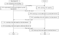
- Embodiment 5 illustrates an example of a flowchart of wireless transmission, as shown in FIG. 5 .
- a base station N 1 is a maintenance base station for a serving cell of a UE U 2 .
- the base station N 1 transmits a first signaling in S 10 , transmits a second radio signal in a second time interval in S 110 , receives a first radio signal in a first time interval in S 11 , and transmits a third radio signal in a third time interval in S 12 .
- the UE U 2 receives a first signaling in S 20 , receives a second radio signal in a second time interval in S 210 , transmits a first radio signal in a first time interval in S 21 , and monitors a third radio signal in a third time interval in S 22 .
- the second time interval is before the first time interval.
- the first radio signal includes first information
- the second radio signal includes second information.
- Target information is used for a multi-antenna related receiving in the third time interval.
- a time-domain position of the second time interval is used for determining whether the target information is the first information or the second information.
- a time-domain position of the third time interval is associated to a time-domain position of the first time interval.
- the first information is used for determining at least one of a first antenna port group or an index of a first vector group, the first antenna port group includes a positive integer number of antenna port(s), and the first vector group includes a positive integer number of vector(s) used for an Rx-beam.
- the second information indicates an index of a second vector group, and the second vector group includes a positive integer number of vector(s) used for an Rx-beam.
- the first time interval and the second time interval are before the third time interval respectively. If the second time interval belongs to a first time window, the target information is the second information; otherwise, the target information is the first information.
- the first time window is before the third time interval.
- the first signaling is used for determining at least one of a candidate antenna port group set, a first candidate vector group set or a second candidate vector group set.
- the first antenna port group is one candidate antenna port group in the candidate antenna port group set.
- the first vector group is one first candidate vector group in the first candidate vector group set.
- the second vector group is one second candidate vector group in the second candidate vector group set.
- a physical layer channel corresponding to the first radio signal is one of a Physical Uplink Control Channel (PUCCH), a Short Latency Physical Uplink Control Channel (SPUCCH) or a New Radio Physical Uplink Control Channel (NR-PUCCH).
- PUCCH Physical Uplink Control Channel
- SPUCCH Short Latency Physical Uplink Control Channel
- NR-PUCCH New Radio Physical Uplink Control Channel
- a physical layer channel corresponding to the second radio signal is one of a Physical Downlink Control Channel (PDCCH), a Short Latency Physical Downlink Control Channel (SPDCCH) or a NR-PDCCH(New Radio Physical Downlink Control Channel (NR-PDCCH).
- PDCH Physical Downlink Control Channel
- SPDCCH Short Latency Physical Downlink Control Channel
- NR-PDCCH New Radio Physical Downlink Control Channel
- a physical layer channel corresponding to the third radio signal is one of a PDCCH, an SPDCCH or an NR-PDCCH.
- the first time interval is before the second time interval.
- the first time interval is behind the second time interval.
- the first information is used for determining at least one of a first antenna port group or an index of a first vector group, the first antenna port group includes a positive integer number of antenna port(s), and the first vector group includes a positive integer number of vector(s) used for an Rx-beam.
- the second information indicates an index of a second vector group, and the second vector group includes a positive integer number of vector(s) used for an Rx-beam.
- the first time interval and the second time interval are before the third time interval respectively. If the second time interval belongs to a first time window, the target information is the second information; otherwise, the target information is the first information.
- the first time window is before the third time interval.
- At least one of a start time of the first time window or an end time of the first time window is associated with a time-domain position of the first time interval.
- At least one of a start time of the first time window or an end time of the first time window is indicated implicitly by the first time interval.
- the antenna port in the first antenna port group is used for transmitting a Channel Status Information Reference Signal (CSI-RS).
- CSI-RS Channel Status Information Reference Signal
- Embodiment 6 illustrates an example of a diagram of a first antenna port group according to the disclosure, as shown in FIG. 6 .
- the first antenna port group belongs to a candidate antenna port group set
- the candidate antenna port group set includes M candidate antenna port groups.
- the M candidate antenna port groups are one-to-one corresponding to M time units.
- a dashed box shown in FIG. 6 corresponds to the candidate antenna port group set.
- different candidate antenna port groups include a same number of antenna ports.
- At least two different candidate antenna port groups include different numbers of antenna ports.
- any one of the M time units occupies a same number of Orthogonal Frequency Division Multiplexing (OFDM) symbols.
- OFDM Orthogonal Frequency Division Multiplexing
- two of the M time units occupy different numbers of OFDM symbols.
- the M time units constitute one of a mini-slot, a slot or a subframe.
- a duration of the time unit in time domain is less than the time interval described in the disclosure.
- Embodiment 7 illustrates an example of a diagram of a given vector group according to the disclosure, as shown in FIG. 7 .
- the given vector group belongs to a target candidate vector group set
- the target candidate vector group set includes N target candidate vector groups.
- the N target candidate vector groups are one-to-one corresponding to N time units.
- a dashed box shown in FIG. 7 corresponds to the target candidate vector group set.
- the given vector group is the first vector group in the disclosure
- the target candidate vector group set is the first candidate vector group set in the disclosure
- the target candidate vector group is the first candidate vector group in the disclosure.
- the given vector group is the second vector group in the disclosure
- the target candidate vector group set is the second candidate vector group set in the disclosure
- the target candidate vector group is the second candidate vector group in the disclosure.
- different target candidate vector groups include a same number of antenna ports.
- At least two different target candidate vector groups include different numbers of antenna ports.
- any one of the N time units occupies a same number of OFDM symbols.
- two of the N time units occupy different numbers of OFDM symbols.
- the N time units constitute one of a mini-slot, a slot or a subframe.
- a duration of the time unit in time domain is less than the time interval described in the disclosure.
- Embodiment 8 illustrates an example of a diagram of a first time interval, a second time interval and a third time interval according to the disclosure.
- the first time interval, the second time interval and the third time interval are sequentially arranged in time domain in a chronological order.
- FIG. 8 also shows a second time window and a third time window.
- the UE in the disclosure transmits a first radio signal in the first time interval, receives a second radio signal in the second time interval and monitors a third radio signal in the third time interval.
- the first radio signal includes first information
- the second radio signal includes second information.
- Target information is used for a multi-antenna related receiving in the third time interval.
- the first time window in the disclosure is one of the second time window or the third time window.
- the first time window is the second time window
- the target information is the second information
- the first time window is the third time window
- the target information is the first information
- Embodiment 9 illustrates an example of a diagram of a first time interval, a second time interval and a third time interval according to the disclosure.
- the second time interval, the first time interval and the third time interval are sequentially arranged in time domain in a chronological order.
- FIG. 9 also shows the first time window in the disclosure.
- the UE in the disclosure receives a second radio signal in the second time interval, transmits a first radio signal in the first time interval and monitors a third radio signal in the third time interval.
- the first radio signal includes first information
- the second radio signal includes second information.
- Target information is used for a multi-antenna related receiving in the third time interval.
- the target information is the first information.
- the second information is indicated through a higher-layer signaling.
- a physical layer channel corresponding to the second radio signal is one of a Physical Downlink Shared Channel (PDSCH), a Short Latency PDSCH (SPDSCH) or a New Radio-PDSCH (NR-PDSCH).
- PDSCH Physical Downlink Shared Channel
- SPDSCH Short Latency PDSCH
- NR-PDSCH New Radio-PDSCH
- Embodiment 10 illustrates an example of a structure block diagram of a processing device in a UE, as shown in FIG. 10 .
- the processing device 1000 in the UE includes a first transceiver 1001 and a first receiver 1002 .
- the first transceiver 1001 transmits a first radio signal in a first time interval, and receives a second radio signal in a second time interval.
- the first receiver 1002 monitors a third radio signal in a third time interval.
- the first radio signal includes first information
- the second radio signal includes second information.
- Target information is used for a multi-antenna related receiving in the third time interval.
- a time-domain position of the second time interval is used for determining whether the target information is the first information or the second information.
- a time-domain position of the third time interval is associated to a time-domain position of the first time interval.
- the first information is used for determining at least one of a first antenna port group or an index of a first vector group, the first antenna port group includes a positive integer number of antenna port(s), and the first vector group includes a positive integer number of vector(s) used for an Rx-beam.
- the second information indicates an index of a second vector group, and the second vector group includes a positive integer number of vector(s) used for an Rx-beam.
- the first time interval and the second time interval are before the third time interval respectively. If the second time interval belongs to a first time window, the target information is the second information; otherwise, the target information is the first information.
- the first time window is before the third time interval.
- the first transceiver 1001 receives a first signaling.
- the first signaling is used for determining at least one of a candidate antenna port group set, a first candidate vector group set or a second candidate vector group set.
- the first antenna port group is one candidate antenna port group in the candidate antenna port group set.
- the first vector group is one first candidate vector group in the first candidate vector group set.
- the second vector group is one second candidate vector group in the second candidate vector group set.
- the third radio signal is used for transmitting a DCI, and the first receiver 1002 performs blind decoding of the third radio signal in the third time interval.
- the third radio signal is one of a PDCCH, an SPDCCH or an NR-PDCCH specific to the UE.
- the first information is used for determining at least one of a first antenna port group or an index of a first vector group, the first antenna port group includes a positive integer number of antenna port(s), and the first vector group includes a positive integer number of vector(s) used for an Rx-beam.
- the second information indicates an index of a second vector group, and the second vector group includes a positive integer number of vector(s) used for an Rx-beam.
- the first time interval and the second time interval are before the third time interval respectively. If the second time interval belongs to the first time window, the target information is the second information; otherwise, the target information is the first information.
- the first time window is before the third time interval.
- the first transceiver 1001 includes at least the former six of the antenna 452 , the transmitter/receiver 454 , the multi-antenna transmitting processor 457 , the multi-antenna receiving processor 458 , the transmitting processor 458 , the receiving processor 456 and the controller/processor 459 illustrated in Embodiment 4.
- the first receiver 1002 includes at least the former four of the antenna 452 , the receiver 454 , the multi-antenna receiving processor 458 , the receiving processor 456 and the controller/processor 459 illustrated in Embodiment 4.
- Embodiment 11 illustrates an example of a structure block diagram of a processing device in a base station, as shown in FIG. 11 .
- the processing device 1100 in the base station includes a second transceiver 1101 and a first transmitter 1102 .
- the second transceiver 1101 receives a first radio signal in a first time interval, and transmits a second radio signal in a second time interval.
- the first transmitter 1102 transmits a third radio signal in a third time interval.
- the first radio signal includes first information
- the second radio signal includes second information.
- Target information is used for a multi-antenna related receiving in the third time interval.
- a time-domain position of the second time interval is used for determining whether the target information is the first information or the second information.
- a time-domain position of the third time interval is associated to a time-domain position of the first time interval.
- the first information is used for determining at least one of a first antenna port group or an index of a first vector group, the first antenna port group includes a positive integer number of antenna port(s), and the first vector group includes a positive integer number of vector(s) used for an Rx-beam.
- the second information indicates an index of a second vector group, and the second vector group includes a positive integer number of vector(s) used for an Rx-beam.
- the first time interval and the second time interval are before the third time interval respectively. If the second time interval belongs to a first time window, the target information is the second information; otherwise, the target information is the first information.
- the first time window is before the third time interval.
- the second transceiver 1101 transmits a first signaling.
- the first signaling is used for determining at least one of a candidate antenna port group set, a first candidate vector group set or a second candidate vector group set.
- the first antenna port group is one candidate antenna port group in the candidate antenna port group set.
- the first vector group is one first candidate vector group in the first candidate vector group set.
- the second vector group is one second candidate vector group in the second candidate vector group set.
- the third radio signal is one of a PDCCH, an SPDCCH or an NR-PDCCH specific to the UE.
- the first information is used for determining at least one of a first antenna port group or an index of a first vector group, the first antenna port group includes a positive integer number of antenna port(s), and the first vector group includes a positive integer number of vector(s) used for an Rx-beam.
- the second information indicates an index of a second vector group, and the second vector group includes a positive integer number of vector(s) used for an Rx-beam.
- the first time interval and the second time interval are before the third time interval respectively. If the second time interval belongs to a first time window, the target information is the second information; otherwise, the target information is the first information.
- the first time window is before the third time interval.
- the second transceiver 1201 includes at least the former six of the antenna 420 , the transmitter/receiver 418 , the multi-antenna transmitting processor 471 , the multi-antenna receiving processor 472 , the transmitting processor 416 , the receiving processor 470 and the controller/processor 475 illustrated in Embodiment 4.
- the first transmitter 1202 includes at least the former four of the antenna 420 , the transmitter 418 , the multi-antenna transmitting processor 471 , the transmitting processor 416 and the controller/processor 475 illustrated in Embodiment 4.
- Embodiment 12 illustrates an example of a flowchart of wireless transmission, as shown in FIG. 12 .
- a base station N 3 is a maintenance base station for a serving cell of a UE U 4 .
- the base station N 3 receives a first radio signal in a first time interval in S 31 , and transmits a second radio signal in a second time interval in S 310 .
- the UE U 4 transmits a first radio signal in a first time interval in S 41 , and receives a second radio signal in a second time interval in S 410 .
- the first time interval is before the second time interval.
- the first time interval and the second time interval include a positive integer number of OFDM symbols respectively.
- each module unit in the above embodiment may be realized in the form of hardware, or in the form of software function modules. The disclosure is not limited to any combination of hardware and software in specific forms.
- the UE and terminal in the disclosure include but not limited to mobile phones, tablet computers, notebooks, vehicle-mounted communication equipment, wireless sensor, network cards, terminals for Internet of Things, REID terminals, NB-IOT terminals, Machine Type Communication (MTC) terminals, enhanced MTC (eMTC) terminals, data cards, low-cost mobile phones, low-cost tablet computers, and other radio communication equipment.
- the base station in the disclosure includes but not limited to macro-cellular base stations, micro-cellular base stations, home base stations, relay base station, and other radio communication equipment.
Landscapes
- Engineering & Computer Science (AREA)
- Signal Processing (AREA)
- Computer Networks & Wireless Communication (AREA)
- Physics & Mathematics (AREA)
- Mathematical Physics (AREA)
- Mobile Radio Communication Systems (AREA)
Abstract
Description
-
- transmitting a first radio signal in a first time interval, and receiving a second radio signal in a second time interval; and
- monitoring a third radio signal in a third time interval.
-
- receiving a first signaling.
-
- receiving a first radio signal in a first time interval, and transmitting a second radio signal in a second time interval; and
- transmitting a third radio signal in a third time interval.
-
- transmitting a first signaling.
-
- a first transceiver, to transmit a first radio signal in a first time interval, and to receive a second radio signal in a second time interval; and
- a first receiver, to monitor a third radio signal in a third time interval.
-
- a second transceiver, to receive a first radio signal in a first time interval, and to transmit a second radio signal in a second time interval; and
- a first transmitter, to transmit a third radio signal in a third time interval.
Claims (16)
Priority Applications (4)
| Application Number | Priority Date | Filing Date | Title |
|---|---|---|---|
| US17/516,718 US11616554B2 (en) | 2017-03-16 | 2021-11-02 | Method and device in UE and base station for multi-antenna transmission |
| US18/173,193 US11949482B2 (en) | 2017-03-16 | 2023-02-23 | Method and device in UE and base station for multi-antenna transmission |
| US18/587,245 US12244385B2 (en) | 2017-03-16 | 2024-02-26 | Method and device in UE and base station for multi-antenna transmission |
| US19/068,524 US20250266887A1 (en) | 2017-03-16 | 2025-03-03 | Method and device in ue and base station for multi-antenna transmission |
Applications Claiming Priority (1)
| Application Number | Priority Date | Filing Date | Title |
|---|---|---|---|
| PCT/CN2017/076965 WO2018165946A1 (en) | 2017-03-16 | 2017-03-16 | User equipment for multi-antenna transmission, and method and apparatus in base station |
Related Parent Applications (1)
| Application Number | Title | Priority Date | Filing Date |
|---|---|---|---|
| PCT/CN2017/076965 Continuation WO2018165946A1 (en) | 2017-03-16 | 2017-03-16 | User equipment for multi-antenna transmission, and method and apparatus in base station |
Related Child Applications (1)
| Application Number | Title | Priority Date | Filing Date |
|---|---|---|---|
| US17/516,718 Continuation US11616554B2 (en) | 2017-03-16 | 2021-11-02 | Method and device in UE and base station for multi-antenna transmission |
Publications (2)
| Publication Number | Publication Date |
|---|---|
| US20190386732A1 US20190386732A1 (en) | 2019-12-19 |
| US11201656B2 true US11201656B2 (en) | 2021-12-14 |
Family
ID=63523700
Family Applications (5)
| Application Number | Title | Priority Date | Filing Date |
|---|---|---|---|
| US16/554,566 Active US11201656B2 (en) | 2017-03-16 | 2019-08-28 | Method and device in UE and base station for multi-antenna transmission |
| US17/516,718 Active US11616554B2 (en) | 2017-03-16 | 2021-11-02 | Method and device in UE and base station for multi-antenna transmission |
| US18/173,193 Active US11949482B2 (en) | 2017-03-16 | 2023-02-23 | Method and device in UE and base station for multi-antenna transmission |
| US18/587,245 Active US12244385B2 (en) | 2017-03-16 | 2024-02-26 | Method and device in UE and base station for multi-antenna transmission |
| US19/068,524 Pending US20250266887A1 (en) | 2017-03-16 | 2025-03-03 | Method and device in ue and base station for multi-antenna transmission |
Family Applications After (4)
| Application Number | Title | Priority Date | Filing Date |
|---|---|---|---|
| US17/516,718 Active US11616554B2 (en) | 2017-03-16 | 2021-11-02 | Method and device in UE and base station for multi-antenna transmission |
| US18/173,193 Active US11949482B2 (en) | 2017-03-16 | 2023-02-23 | Method and device in UE and base station for multi-antenna transmission |
| US18/587,245 Active US12244385B2 (en) | 2017-03-16 | 2024-02-26 | Method and device in UE and base station for multi-antenna transmission |
| US19/068,524 Pending US20250266887A1 (en) | 2017-03-16 | 2025-03-03 | Method and device in ue and base station for multi-antenna transmission |
Country Status (3)
| Country | Link |
|---|---|
| US (5) | US11201656B2 (en) |
| CN (3) | CN113452497A (en) |
| WO (1) | WO2018165946A1 (en) |
Cited By (3)
| Publication number | Priority date | Publication date | Assignee | Title |
|---|---|---|---|---|
| US20220086815A1 (en) * | 2018-02-13 | 2022-03-17 | Shanghai Langbo Communication Technology Company Limited | Method and device in communication node used for wireless communication |
| US11412506B2 (en) * | 2018-09-13 | 2022-08-09 | Shanghai Langbo Communication Technology Company Limited | Method and device used in node for wireless communication |
| US12244385B2 (en) | 2017-03-16 | 2025-03-04 | Didi Wireless Innovatins, LLC | Method and device in UE and base station for multi-antenna transmission |
Families Citing this family (2)
| Publication number | Priority date | Publication date | Assignee | Title |
|---|---|---|---|---|
| US11309949B2 (en) * | 2017-09-14 | 2022-04-19 | Guangdong Oppo Mobile Telecommunications Corp., Ltd. | Signal processing method and apparatus |
| CN114374488B (en) * | 2020-10-15 | 2024-08-16 | 上海朗帛通信技术有限公司 | Method and apparatus in a node for wireless communication |
Citations (12)
| Publication number | Priority date | Publication date | Assignee | Title |
|---|---|---|---|---|
| CN101459457A (en) | 2007-12-12 | 2009-06-17 | 鼎桥通信技术有限公司 | Wave beam shaping method |
| CN102668406A (en) | 2009-11-02 | 2012-09-12 | 高通股份有限公司 | Method and device for random access signal transmission in wireless communication system |
| WO2014139174A1 (en) | 2013-03-15 | 2014-09-18 | Qualcomm Incorporated | Improved random access procedure with beamforming in lte |
| CN104272605A (en) | 2012-05-09 | 2015-01-07 | 交互数字专利控股公司 | Multi-user MIMO communication in WLAN and wireless transmit and receive units |
| US20150124679A1 (en) * | 2008-06-18 | 2015-05-07 | Optis Cellular Technology, Llc | Method for performing random access procedures and terminal thereof |
| CN104956606A (en) | 2013-01-25 | 2015-09-30 | 交互数字专利控股公司 | Method and apparatus for vertical beamforming |
| CN105122676A (en) | 2013-04-05 | 2015-12-02 | Lg电子株式会社 | Method for transmitting uplink control information in wireless access system and apparatus therefor |
| WO2016006964A1 (en) | 2014-07-10 | 2016-01-14 | 삼성전자 주식회사 | Communication method and system in wireless communication system using beamforming scheme |
| CN105429683A (en) | 2014-09-17 | 2016-03-23 | 上海朗帛通信技术有限公司 | A 3D MIMO transmission method and device |
| CN106105311A (en) | 2015-02-28 | 2016-11-09 | 华为技术有限公司 | The method of a kind of data transmission, device and user equipment and system |
| CN106374984A (en) | 2015-07-20 | 2017-02-01 | 中兴通讯股份有限公司 | Wave beam updating methods and equipment |
| WO2017030601A1 (en) | 2015-08-20 | 2017-02-23 | Intel IP Corporation | Transmit beamforming |
Family Cites Families (8)
| Publication number | Priority date | Publication date | Assignee | Title |
|---|---|---|---|---|
| US8441996B2 (en) * | 2009-04-02 | 2013-05-14 | Lg Electronics Inc. | Method and apparatus for monitoring control channel in multiple carrier system |
| US8238234B2 (en) * | 2009-06-03 | 2012-08-07 | Qualcomm Incorporated | Switching between MIMO and receiver beam forming in a peer-to-peer network |
| WO2011155777A2 (en) * | 2010-06-09 | 2011-12-15 | 엘지전자 주식회사 | Method and device for transmitting/receiving channel state information in wireless communication system supporting multicarriers |
| KR101655924B1 (en) * | 2012-03-07 | 2016-09-08 | 엘지전자 주식회사 | Method for performing hierarchical beamforming in wireless access system and device therefor |
| US10015788B2 (en) * | 2014-04-17 | 2018-07-03 | Blinq Wireless Inc. | System and method of signalling for point-to-multipoint (PtMP) transmission in fixed wireless backhaul networks |
| JP6406777B2 (en) * | 2014-09-23 | 2018-10-17 | ホアウェイ・テクノロジーズ・カンパニー・リミテッド | Beam configuration method, base station, and user equipment |
| CN105119640B (en) * | 2015-08-03 | 2019-04-26 | 上海华为技术有限公司 | A kind of switching method and device of antenna mode |
| CN113452497A (en) | 2017-03-16 | 2021-09-28 | 上海朗帛通信技术有限公司 | Method and device in user equipment and base station used for multi-antenna transmission |
-
2017
- 2017-03-16 CN CN202110647937.8A patent/CN113452497A/en active Pending
- 2017-03-16 CN CN202110646696.5A patent/CN113452496B/en active Active
- 2017-03-16 WO PCT/CN2017/076965 patent/WO2018165946A1/en not_active Ceased
- 2017-03-16 CN CN201780069301.1A patent/CN109964413B/en active Active
-
2019
- 2019-08-28 US US16/554,566 patent/US11201656B2/en active Active
-
2021
- 2021-11-02 US US17/516,718 patent/US11616554B2/en active Active
-
2023
- 2023-02-23 US US18/173,193 patent/US11949482B2/en active Active
-
2024
- 2024-02-26 US US18/587,245 patent/US12244385B2/en active Active
-
2025
- 2025-03-03 US US19/068,524 patent/US20250266887A1/en active Pending
Patent Citations (13)
| Publication number | Priority date | Publication date | Assignee | Title |
|---|---|---|---|---|
| CN101459457A (en) | 2007-12-12 | 2009-06-17 | 鼎桥通信技术有限公司 | Wave beam shaping method |
| US20150124679A1 (en) * | 2008-06-18 | 2015-05-07 | Optis Cellular Technology, Llc | Method for performing random access procedures and terminal thereof |
| CN102668406A (en) | 2009-11-02 | 2012-09-12 | 高通股份有限公司 | Method and device for random access signal transmission in wireless communication system |
| CN104272605A (en) | 2012-05-09 | 2015-01-07 | 交互数字专利控股公司 | Multi-user MIMO communication in WLAN and wireless transmit and receive units |
| CN104956606A (en) | 2013-01-25 | 2015-09-30 | 交互数字专利控股公司 | Method and apparatus for vertical beamforming |
| WO2014139174A1 (en) | 2013-03-15 | 2014-09-18 | Qualcomm Incorporated | Improved random access procedure with beamforming in lte |
| CN105122676A (en) | 2013-04-05 | 2015-12-02 | Lg电子株式会社 | Method for transmitting uplink control information in wireless access system and apparatus therefor |
| WO2016006964A1 (en) | 2014-07-10 | 2016-01-14 | 삼성전자 주식회사 | Communication method and system in wireless communication system using beamforming scheme |
| CN105429683A (en) | 2014-09-17 | 2016-03-23 | 上海朗帛通信技术有限公司 | A 3D MIMO transmission method and device |
| CN106105311A (en) | 2015-02-28 | 2016-11-09 | 华为技术有限公司 | The method of a kind of data transmission, device and user equipment and system |
| CN106374984A (en) | 2015-07-20 | 2017-02-01 | 中兴通讯股份有限公司 | Wave beam updating methods and equipment |
| WO2017030601A1 (en) | 2015-08-20 | 2017-02-23 | Intel IP Corporation | Transmit beamforming |
| US20180212659A1 (en) * | 2015-08-20 | 2018-07-26 | Intel IP Corporation | Transmit beamforming |
Non-Patent Citations (6)
| Title |
|---|
| 1st Office Action in CN application No. 201780069301.1 dated Jan. 26, 2021. |
| 1st Search Report in CN application No. 201780069301.1 dated Jan. 17, 2021. |
| 2nd Office Action in CN application No. 201780069301.1 dated Apr. 19, 2021. |
| ISR received in application No. PCT/CN2017/076965 dated Dec. 8, 2017. |
| Issue notification in CN application No. 201780069301.1 dated Jun. 2, 2021. |
| Supplementary Search Report in CN application No. 201780069301.1 dated Mar. 31, 2021. |
Cited By (6)
| Publication number | Priority date | Publication date | Assignee | Title |
|---|---|---|---|---|
| US12244385B2 (en) | 2017-03-16 | 2025-03-04 | Didi Wireless Innovatins, LLC | Method and device in UE and base station for multi-antenna transmission |
| US20220086815A1 (en) * | 2018-02-13 | 2022-03-17 | Shanghai Langbo Communication Technology Company Limited | Method and device in communication node used for wireless communication |
| US11523385B2 (en) * | 2018-02-13 | 2022-12-06 | Shanghai Langbo Communication Technology Company Limited | Method and device in communication node used for wireless communication |
| US20230044234A1 (en) * | 2018-02-13 | 2023-02-09 | Shanghai Langbo Communication Technology Company Limited | Method and device in communication node used for wireless communication |
| US11696264B2 (en) * | 2018-02-13 | 2023-07-04 | Shanghai Langbo Communication Technology Company Limited | Method and device in communication node used for wireless communication |
| US11412506B2 (en) * | 2018-09-13 | 2022-08-09 | Shanghai Langbo Communication Technology Company Limited | Method and device used in node for wireless communication |
Also Published As
| Publication number | Publication date |
|---|---|
| US11949482B2 (en) | 2024-04-02 |
| US12244385B2 (en) | 2025-03-04 |
| US20250266887A1 (en) | 2025-08-21 |
| CN109964413B (en) | 2021-07-27 |
| CN109964413A (en) | 2019-07-02 |
| CN113452496B (en) | 2022-06-21 |
| US20220060237A1 (en) | 2022-02-24 |
| WO2018165946A1 (en) | 2018-09-20 |
| US20240283514A1 (en) | 2024-08-22 |
| US20190386732A1 (en) | 2019-12-19 |
| US20230283347A1 (en) | 2023-09-07 |
| CN113452496A (en) | 2021-09-28 |
| US11616554B2 (en) | 2023-03-28 |
| CN113452497A (en) | 2021-09-28 |
Similar Documents
| Publication | Publication Date | Title |
|---|---|---|
| US11949482B2 (en) | Method and device in UE and base station for multi-antenna transmission | |
| US12052196B2 (en) | Method and device in communication node used for wireless communication | |
| US11032833B2 (en) | Method and device for dynamic scheduling in UE and base station | |
| US12047958B2 (en) | Method and device in nodes used for wireless communication | |
| US11950272B2 (en) | Method and device in wireless transmission | |
| US11102798B2 (en) | Method and device in UE and base station used for wireless communication | |
| US11757566B2 (en) | Method and device in UE and base station for multi-antenna communication | |
| US12317208B2 (en) | User equipment and base station for wireless communication and methods of using same | |
| US12245058B2 (en) | Method and device in first node for wireless communication | |
| EP4245002B1 (en) | Method and device in node for wireless communication | |
| US20230362667A1 (en) | Method and device in a node used for wireless communication | |
| WO2019014922A1 (en) | Method and device for user and base station for beam forming | |
| CN113923779A (en) | Method and apparatus in a node used for wireless communication | |
| CN115580381B (en) | A method and device used in a node for wireless communication | |
| CN115549869A (en) | Method and apparatus in a node used for wireless communication |
Legal Events
| Date | Code | Title | Description |
|---|---|---|---|
| AS | Assignment |
Owner name: SHANGHAI LANGBO COMMUNICATION TECHNOLOGY COMPANY LIMITED, CHINA Free format text: ASSIGNMENT OF ASSIGNORS INTEREST;ASSIGNOR:ZHANG, XIAOBO;REEL/FRAME:050205/0582 Effective date: 20190805 Owner name: SHANGHAI LANGBO COMMUNICATION TECHNOLOGY COMPANY L Free format text: ASSIGNMENT OF ASSIGNORS INTEREST;ASSIGNOR:ZHANG, XIAOBO;REEL/FRAME:050205/0582 Effective date: 20190805 |
|
| FEPP | Fee payment procedure |
Free format text: ENTITY STATUS SET TO UNDISCOUNTED (ORIGINAL EVENT CODE: BIG.); ENTITY STATUS OF PATENT OWNER: SMALL ENTITY |
|
| FEPP | Fee payment procedure |
Free format text: ENTITY STATUS SET TO SMALL (ORIGINAL EVENT CODE: SMAL); ENTITY STATUS OF PATENT OWNER: SMALL ENTITY |
|
| STPP | Information on status: patent application and granting procedure in general |
Free format text: DOCKETED NEW CASE - READY FOR EXAMINATION |
|
| STPP | Information on status: patent application and granting procedure in general |
Free format text: RESPONSE TO NON-FINAL OFFICE ACTION ENTERED AND FORWARDED TO EXAMINER |
|
| STPP | Information on status: patent application and granting procedure in general |
Free format text: FINAL REJECTION MAILED |
|
| STPP | Information on status: patent application and granting procedure in general |
Free format text: RESPONSE AFTER FINAL ACTION FORWARDED TO EXAMINER |
|
| STPP | Information on status: patent application and granting procedure in general |
Free format text: ADVISORY ACTION MAILED |
|
| STPP | Information on status: patent application and granting procedure in general |
Free format text: DOCKETED NEW CASE - READY FOR EXAMINATION |
|
| STPP | Information on status: patent application and granting procedure in general |
Free format text: NOTICE OF ALLOWANCE MAILED -- APPLICATION RECEIVED IN OFFICE OF PUBLICATIONS |
|
| STPP | Information on status: patent application and granting procedure in general |
Free format text: PUBLICATIONS -- ISSUE FEE PAYMENT RECEIVED |
|
| STPP | Information on status: patent application and granting procedure in general |
Free format text: PUBLICATIONS -- ISSUE FEE PAYMENT VERIFIED |
|
| STCF | Information on status: patent grant |
Free format text: PATENTED CASE |
|
| AS | Assignment |
Owner name: DIDO WIRELESS INNOVATIONS LLC, TEXAS Free format text: ASSIGNMENT OF ASSIGNORS INTEREST;ASSIGNOR:SHANGHAI LANGBO COMMUNICATION TECHNOLOGY CO., LTD.;REEL/FRAME:062084/0077 Effective date: 20221130 |
|
| MAFP | Maintenance fee payment |
Free format text: PAYMENT OF MAINTENANCE FEE, 4TH YR, SMALL ENTITY (ORIGINAL EVENT CODE: M2551); ENTITY STATUS OF PATENT OWNER: SMALL ENTITY Year of fee payment: 4 |