US1119829A - Skylight. - Google Patents
Skylight. Download PDFInfo
- Publication number
- US1119829A US1119829A US67585912A US1912675859A US1119829A US 1119829 A US1119829 A US 1119829A US 67585912 A US67585912 A US 67585912A US 1912675859 A US1912675859 A US 1912675859A US 1119829 A US1119829 A US 1119829A
- Authority
- US
- United States
- Prior art keywords
- trough
- plates
- astragal
- glass
- housing
- Prior art date
- Legal status (The legal status is an assumption and is not a legal conclusion. Google has not performed a legal analysis and makes no representation as to the accuracy of the status listed.)
- Expired - Lifetime
Links
- 241001061264 Astragalus Species 0.000 description 23
- 239000011521 glass Substances 0.000 description 18
- 238000010276 construction Methods 0.000 description 12
- 230000008093 supporting effect Effects 0.000 description 12
- XLYOFNOQVPJJNP-UHFFFAOYSA-N water Substances O XLYOFNOQVPJJNP-UHFFFAOYSA-N 0.000 description 8
- 238000007373 indentation Methods 0.000 description 6
- 230000008602 contraction Effects 0.000 description 4
- 229910000746 Structural steel Inorganic materials 0.000 description 3
- 239000002184 metal Substances 0.000 description 3
- 229910052751 metal Inorganic materials 0.000 description 3
- XEEYBQQBJWHFJM-UHFFFAOYSA-N Iron Chemical compound [Fe] XEEYBQQBJWHFJM-UHFFFAOYSA-N 0.000 description 2
- 229910052742 iron Inorganic materials 0.000 description 1
- JEIPFZHSYJVQDO-UHFFFAOYSA-N iron(III) oxide Inorganic materials O=[Fe]O[Fe]=O JEIPFZHSYJVQDO-UHFFFAOYSA-N 0.000 description 1
- 238000012986 modification Methods 0.000 description 1
- 230000004048 modification Effects 0.000 description 1
- 229920000136 polysorbate Polymers 0.000 description 1
- 230000002265 prevention Effects 0.000 description 1
Images

Classifications
-
- E—FIXED CONSTRUCTIONS
- E04—BUILDING
- E04D—ROOF COVERINGS; SKY-LIGHTS; GUTTERS; ROOF-WORKING TOOLS
- E04D3/00—Roof covering by making use of flat or curved slabs or stiff sheets
- E04D3/02—Roof covering by making use of flat or curved slabs or stiff sheets of plane slabs, slates, or sheets, or in which the cross-section is unimportant
- E04D3/06—Roof covering by making use of flat or curved slabs or stiff sheets of plane slabs, slates, or sheets, or in which the cross-section is unimportant of glass or other translucent material; Fixing means therefor
- E04D3/08—Roof covering by making use of flat or curved slabs or stiff sheets of plane slabs, slates, or sheets, or in which the cross-section is unimportant of glass or other translucent material; Fixing means therefor with metal glazing bars
Definitions
- My invention relates to roof constructions of glass and particularly to sky-light constructions.
- a means is provided for securing and yet allowing the expansion and contraction of the supporting beams, a means is also provided for the protection of the glass plates and for tightly closing the roof and skylight, a means is also provided for collect ing all the water that may be condensed on the under surface of the glass and also col lect all water that may leak through or be forced or driven between the joints of or cracks of the construction.
- One form of construction containing the invention is provided with a means which will not only cushion the glass but will also .-prevent leakage and will collect all the water condensed or forced into the construction and direct it into an open and unobstructed trough.
- the invention may be contained in a number of constructions. One of such con structions is shown in the drawings. The same is described hereinafter to show how a construction embodying the invention may be made and to show that the invention when so embodied is operative.
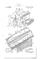
- Figure 1 shows the supporting construction for the sky-light.
- Fig. 2 illustrates a cross section of an astragal used for supporting the glass panels.
- Figs. 3 and -l show the means for supporting the ends of the. astragal.
- Fig. 5 is a longitudinal section through the supporting housing shown in Fig. 4.
- Fig. 6 is a modification of the invention.
- 1 is the astragal supported on the curb 2 of the roof of the building and the ridge 3.
- l and 5 are the means for securing the astragal in position and vet allowing free movement of the parts of the sky-light caused by the shaking Specification of Letters Patent.
- the astragal consists of a trough the interior of which is practically unobstructed in order that the collection of water may be facilitated and which can be painted easily for the prevention of rust.
- the trough 6 has a flat bottom 7 so that it can be, if desired, laid on another beam that may be contained in the structure in which the skylight is built or located. It also permits the free flow of the water collected. If desired it may be provided with flaring walls 8. It found preferable to make the walls flaring in order to receive the water delivered from the cross troughs 10 located at the ends. of the plates of the glass which collect the water drained from the bottom of the plates or that may be forced into the interior of the building at the joints or cracks be tween the adjoining ends of the plates.
- Brackets 11 are secured at intervals along the trough.
- the legs of the brackets are socured to the walls 8 by means of rivets or screws 19.
- the brackets are angled inward as at 13 which not only makes them strong supporting structures but also they permit the cross trough to be placed at any points or the bracket-s may be placed at any points without respect to the location of the ends of the plates where the cross troughs are located.
- a T-beam 14 is supported on the brackets, the cross web being secured to the brackets by means of rivets or screws 15.
- the edges of the glass plates 16 of adjoining panels extend over the cross-web of the T-beam and side portions of the glass plates of considerable width. are located above the cross-web and are supported on the cross-web giving larIge bearing surfaces for the plates.
- lead cushioning aprons 17 formed of strips of considerable width are located between the edges of the glass plates and the two webs of the beam.
- the aprons extend from a point slightly above the upper surfaces of the glass downward along the central web of the beam and then over the upper surface of the cross-web on both sides of the central web and then down to a point slightly below the lower surface of the cross-web.
- the upper edges of the aprons on the plate sides by reason of the nature of the metal of which they are constructed II": 1 Jud soon extends or hangs over the upper corners of the edges of the plates. The aprons are thus so constructed that they will very perfectly cushion the glass plates.
- the corners of the glass plates are separated from the iron, contact with which would cause their fracture upon the slightest jar or vibration of the building.
- the aprons extend vertically downward between the lateral edges of the plates and the beam and then over the upper surface of the portion of the beam on which the plates rest forming a wide cushion extending the full length of the panels on which the plates are supported. The plates thus safely withstand any pressure or vibration of the structure.
- Screw bolts 18 are located on the top of the central web of the beam 14: and at intervals along the beam.
- a sheet metal cap 9 is located above the beam and is placed over the bolts which pass through holes formed in the elastic cap 9. The.
- the caps 9 rest upon the glass plates.
- the cap is compressed by means of the nuts 20 which are screwed onto the bolts 18 thus pressing the edges of the cap against the surfaces of the glass plates.
- the caps 19 shelter the beam and assist in holding the plates against the cushion aprons 17.
- the ends of the astragal are supported in housings 1' and 5 located on the curb or on the ridge or other part of the roof.
- the upper end of the astragal is supported in the housing 5 which is secured in this case to the ridge 3 of the roof of the building. This is shown in section in Fig. 3.
- the trough 6 is placed on the bottoms of the housings i and 5.
- the upper end of the trough is provided with elongated indentations or recesses 22.
- Round-pointed screws extend through the walls of the housing 5 and into the elongated recesses 22.
- the screws hold the trough in the housing sufiiciently tight to prevent any looseness of the beam and yet allow for the expansion and contraction of the astragal due to heat and vibration of the building with respect to the astragal supporting the glass plates 'and thus prevent communication of the vibrations and jarring of the plates.
- the astragal rests and abuts on and in the housing -l located on the curb 2 of the roof.
- the sheet metal piece 27 may be provided with openings 34:
- An apron 26 covers the which will allow the water to drain down on to the apron 26.
- the housing 4 extends well up under the trough 6 and over the curb. It is made up; of the bottom 29, the side walls 30 and the end plate 31. The ends of the beam 14 and the trough 6 rests against the end plate 31.
- the end plate also closes the end of the cap 19.
- the plate 31 is provided with a tongue 32.
- the tongue 32 has a rounded substantially cylindrical under surface which forms the undersurface of the base portion which is of considerable dimensions while the upper surface is pyramidal, the apex of the pyramid being on the inside surface of the plate. This produces a tongue of considerable s'trength.
- the tongue is constructed not only so it will have considerable strength, but also permits the astragal to be inserted first in the housing 4 at an angle to the bottom of the housing and the upper end of the astragal may be brought down to and dropped into the housing 5 and secured in position by means of the screws 23 suf iciently to prevent looseness of the astragal and yet permit the vibration of the supporting structure and expansion and contraction of the astragal and of the supporting structure.
- the plate 3 1 is also provided with holes 35 which are located at the bottom of the channel iron 39 is located on the brackets 37.
- the edges of the side walls of'the channel iron are provided with lead cushioning devices 40.
- the channel iron is secured by means 'of bolts 43 which extend upward from the brackets 37.
- a lead ferrule 41 is placed over the bolt 43.
- the plates 42 rest upon the lead cushioning devices 40 and are located upon opposite sides of the bolt 43,
- the trough 6 collects the moisture from the plates in. the manner well known in the art and delivers it through the holes located in the housing I.
- the astragal a section of which is shown in Fig. 6 is secured in the structure in substantially the same way that the astragal shown in Fig. 1 is secured.
Landscapes
- Engineering & Computer Science (AREA)
- Architecture (AREA)
- Civil Engineering (AREA)
- Structural Engineering (AREA)
- Roof Covering Using Slabs Or Stiff Sheets (AREA)
Description
A. H. JETBR.
SKYLIGHT.
APPLICATION FILED 1133.3. m2.
Patented Dec. 8. 1914.
2 SHEETS-3112:5211
Fig.5
WITNESSES:
" ATTORNEY E OFFICE.
ALLEN H. JETEB, OF NEW YORK, N. Y.
SKYLIGHT.
To all whom it may concern:
Be it known that 1, ALLEN H. JETER, a citizen of the United States, and a resident of the city of New York, State of New York, have invented a new and useful Iniprovement in Skylights, of which the/following is a specification.
My invention relates to roof constructions of glass and particularly to sky-light constructions.
It has for its object to produce a construction that will protect the glass plates from breaking and which will at the same time prevent any leakage of the roof construction and the sky-light.
In an embodiment of the invention a means is provided for securing and yet allowing the expansion and contraction of the supporting beams, a means is also provided for the protection of the glass plates and for tightly closing the roof and skylight, a means is also provided for collect ing all the water that may be condensed on the under surface of the glass and also col lect all water that may leak through or be forced or driven between the joints of or cracks of the construction.
One form of construction containing the invention is provided with a means which will not only cushion the glass but will also .-prevent leakage and will collect all the water condensed or forced into the construction and direct it into an open and unobstructed trough. v
The invention may be contained in a number of constructions. One of such con structions is shown in the drawings. The same is described hereinafter to show how a construction embodying the invention may be made and to show that the invention when so embodied is operative.
In the figures of the drawings, Figure 1 shows the supporting construction for the sky-light. Fig. 2 illustrates a cross section of an astragal used for supporting the glass panels. Figs. 3 and -l show the means for supporting the ends of the. astragal. Fig. 5 is a longitudinal section through the supporting housing shown in Fig. 4. Fig. 6 is a modification of the invention.
Referring to Figs. 1 and 2, 1 is the astragal supported on the curb 2 of the roof of the building and the ridge 3. l and 5 are the means for securing the astragal in position and vet allowing free movement of the parts of the sky-light caused by the shaking Specification of Letters Patent.
Application filed February 3, 1912. Serial No. 675,859.
of the building and the expansion and contraction of the astragal and such other parts to which it may be connected or by which it may be supported, due to heat.
The astragal consists of a trough the interior of which is practically unobstructed in order that the collection of water may be facilitated and which can be painted easily for the prevention of rust. The trough 6 has a flat bottom 7 so that it can be, if desired, laid on another beam that may be contained in the structure in which the skylight is built or located. It also permits the free flow of the water collected. If desired it may be provided with flaring walls 8. It found preferable to make the walls flaring in order to receive the water delivered from the cross troughs 10 located at the ends. of the plates of the glass which collect the water drained from the bottom of the plates or that may be forced into the interior of the building at the joints or cracks be tween the adjoining ends of the plates.
A T-beam 14 is supported on the brackets, the cross web being secured to the brackets by means of rivets or screws 15. The edges of the glass plates 16 of adjoining panels extend over the cross-web of the T-beam and side portions of the glass plates of considerable width. are located above the cross-web and are supported on the cross-web giving larIge bearing surfaces for the plates.
-'.lhe aprons extend below the lower corners of the cross-web of the beam and thus deliver any moisture that may be collected from the under side of the glass plates directly into the trough and prevent any of it from running back of or up into the crack formed between the aprons and the surface of the beam by capillary attraction. The wide contact surface between the plates and the aprons and between the aprons and the beam prevents leakage of any kind and as they extend the full length of the astragal, they seal the roof making it practically air tight. Screw bolts 18 are located on the top of the central web of the beam 14: and at intervals along the beam. A sheet metal cap 9 is located above the beam and is placed over the bolts which pass through holes formed in the elastic cap 9. The. edges of the cap 9 rest upon the glass plates. The cap is compressed by means of the nuts 20 which are screwed onto the bolts 18 thus pressing the edges of the cap against the surfaces of the glass plates. The caps 19 shelter the beam and assist in holding the plates against the cushion aprons 17. The ends of the astragal are supported in housings 1' and 5 located on the curb or on the ridge or other part of the roof. The upper end of the astragal is supported in the housing 5 which is secured in this case to the ridge 3 of the roof of the building. This is shown in section in Fig. 3. The trough 6 is placed on the bottoms of the housings i and 5. The upper end of the trough is provided with elongated indentations or recesses 22. Round-pointed screws extend through the walls of the housing 5 and into the elongated recesses 22. The screws hold the trough in the housing sufiiciently tight to prevent any looseness of the beam and yet allow for the expansion and contraction of the astragal due to heat and vibration of the building with respect to the astragal supporting the glass plates 'and thus prevent communication of the vibrations and jarring of the plates. The astragal rests and abuts on and in the housing -l located on the curb 2 of the roof. The
ing by means of the screws 28 which pass through the side Wings- 34 of the housing. In order to collect the moisture that may be condensed on the under surface of the lowest plates of the glass panels the sheet metal piece 27 may be provided with openings 34:
An apron 26 covers the which will allow the water to drain down on to the apron 26. v
The housing 4; extends well up under the trough 6 and over the curb. It is made up; of the bottom 29, the side walls 30 and the end plate 31. The ends of the beam 14 and the trough 6 rests against the end plate 31.
The end plate also closes the end of the cap 19. The plate 31 is provided with a tongue 32. The tongue 32 has a rounded substantially cylindrical under surface which forms the undersurface of the base portion which is of considerable dimensions while the upper surface is pyramidal, the apex of the pyramid being on the inside surface of the plate. This produces a tongue of considerable s'trength. The tongue is constructed not only so it will have considerable strength, but also permits the astragal to be inserted first in the housing 4 at an angle to the bottom of the housing and the upper end of the astragal may be brought down to and dropped into the housing 5 and secured in position by means of the screws 23 suf iciently to prevent looseness of the astragal and yet permit the vibration of the supporting structure and expansion and contraction of the astragal and of the supporting structure.
The plate 3 1 is also provided with holes 35 which are located at the bottom of the channel iron 39 is located on the brackets 37. The edges of the side walls of'the channel iron are provided with lead cushioning devices 40. The channel iron is secured by means 'of bolts 43 which extend upward from the brackets 37. A lead ferrule 41 is placed over the bolt 43. The plates 42 rest upon the lead cushioning devices 40 and are located upon opposite sides of the bolt 43,
:m-raaac the ferrule 41. being placed between the plates prevents breaking of the plates, by striking or pressing against the bolts. A cap is placed over the bolts 13, the bolts passing through holes formed in the cap. The edges of the cap are pressed against the upper surface of the plates and the cap is held in position by means of the nuts 46. The trough 6 collects the moisture from the plates in. the manner well known in the art and delivers it through the holes located in the housing I. The astragal, a section of which is shown in Fig. 6 is secured in the structure in substantially the same way that the astragal shown in Fig. 1 is secured.
A great many structures may be made by those skilled in the art which may differ greatly from the structure that I have illustrated and described and yet such structures though diil'erent may still contain my invention. The features of such constructions are described generically in the claims and the equivalents of such features are contemplated as being within the scope of the claims.
What I claim is new and desire o secure by Letters Patent as follows:
1. In an astragal for sky'lights the combination ot'atrough, housings located at the opposite ends-of the said trough for sup porting the said astragal, the upper end of the said trough having elongated indentations located on the outside and on opposite sides of the said trough, screws adapted to 85 extend into the said indentations and frictionally engage opposite sides of the said trough.
2. In an astragal for sky-lights the combination of a trough, housings located at to the opposite ends of the said trough for supporting the said astragal, the upper; end of, the said trough having elongated indentations, round ended screws located in one of the said housings and adapted to extend 45 into the said indentations and frictionally engage the said trough.
3. In an astragal tor skylights the combination of a trough, housings located at the opposite ends of the said trough for supporting the said as tragal, one of the said housings having a nose extending over the bottom of the'said trough and adapted to engage the said trough, the other end of the said trough having elongated indentations ALLEN II. JETER.
Witnesses:
F. F. CRAMPION, E. P. Rrrz.
Priority Applications (1)
| Application Number | Priority Date | Filing Date | Title |
|---|---|---|---|
| US67585912A US1119829A (en) | 1912-02-03 | 1912-02-03 | Skylight. |
Applications Claiming Priority (1)
| Application Number | Priority Date | Filing Date | Title |
|---|---|---|---|
| US67585912A US1119829A (en) | 1912-02-03 | 1912-02-03 | Skylight. |
Publications (1)
| Publication Number | Publication Date |
|---|---|
| US1119829A true US1119829A (en) | 1914-12-08 |
Family
ID=3187996
Family Applications (1)
| Application Number | Title | Priority Date | Filing Date |
|---|---|---|---|
| US67585912A Expired - Lifetime US1119829A (en) | 1912-02-03 | 1912-02-03 | Skylight. |
Country Status (1)
| Country | Link |
|---|---|
| US (1) | US1119829A (en) |
Cited By (4)
| Publication number | Priority date | Publication date | Assignee | Title |
|---|---|---|---|---|
| US20030188500A1 (en) * | 2002-04-05 | 2003-10-09 | Voegele William P. | Panel clip assembly for use with skylight or roof panels |
| US20050102943A1 (en) * | 2003-11-13 | 2005-05-19 | Voegele William P.Jr. | Panel clip assembly for use with roof or wall panels |
| US20070033893A1 (en) * | 2005-08-10 | 2007-02-15 | Voegele Jr William P | Reduced friction fastening clip assembly for use with standing seam roof or wall panel systems |
| US20140260006A1 (en) * | 2013-03-15 | 2014-09-18 | Bellwether Design Technologies, Llc | Skylight and method of fabricating the same |
-
1912
- 1912-02-03 US US67585912A patent/US1119829A/en not_active Expired - Lifetime
Cited By (11)
| Publication number | Priority date | Publication date | Assignee | Title |
|---|---|---|---|---|
| US20030188500A1 (en) * | 2002-04-05 | 2003-10-09 | Voegele William P. | Panel clip assembly for use with skylight or roof panels |
| US6845592B2 (en) * | 2002-04-05 | 2005-01-25 | Extech Exterior Technologies, Inc. | Panel clip assembly for use with skylight or roof panels |
| US20050102943A1 (en) * | 2003-11-13 | 2005-05-19 | Voegele William P.Jr. | Panel clip assembly for use with roof or wall panels |
| US7313893B2 (en) | 2003-11-13 | 2008-01-01 | Extech/Exterior Technologies, Inc. | Panel clip assembly for use with roof or wall panels |
| US20070033893A1 (en) * | 2005-08-10 | 2007-02-15 | Voegele Jr William P | Reduced friction fastening clip assembly for use with standing seam roof or wall panel systems |
| US7661234B2 (en) | 2005-08-10 | 2010-02-16 | Extech/Exterior Technologies, Inc. | Reduced friction fastening clip assembly for use with standing seam roof or wall panel systems |
| US20140260006A1 (en) * | 2013-03-15 | 2014-09-18 | Bellwether Design Technologies, Llc | Skylight and method of fabricating the same |
| US9045905B2 (en) * | 2013-03-15 | 2015-06-02 | Bellwether Design Technologies, Llc | Skylight and method of fabricating the same |
| US9273467B2 (en) | 2013-03-15 | 2016-03-01 | Bellwether Design Technologies, Llc | Skylight and method of fabricating the same |
| US9322177B2 (en) | 2013-03-15 | 2016-04-26 | Bellwether Design Technologies, Llc | Skylight and method of fabricating the same |
| US9328513B2 (en) | 2013-03-15 | 2016-05-03 | Bellwether Design Technologies, Llc | Skylight and method of fabricating the same |
Similar Documents
| Publication | Publication Date | Title |
|---|---|---|
| JPH02501230A (en) | Sealing devices for frontages and/or roofs | |
| US4977721A (en) | Rigid covering for roofs and supports therefor | |
| US1119829A (en) | Skylight. | |
| US2425060A (en) | Skylight construction | |
| FI95956B (en) | Connecting for ceiling elements | |
| US326056A (en) | overman | |
| US981813A (en) | Skylight. | |
| US1386130A (en) | Building construction | |
| JPS61501641A (en) | roof structure | |
| GB2084209A (en) | Repairing gutters | |
| US1833456A (en) | Metal roofing sheet | |
| US1266613A (en) | Skylight and glass-wall structure. | |
| US2419005A (en) | Tile | |
| US951112A (en) | Skylight. | |
| US1835784A (en) | Glazed structure | |
| KR101005191B1 (en) | Connecting member of prefabricated building roof | |
| US508287A (en) | Glass structure | |
| US1734840A (en) | Skylight | |
| KR102351091B1 (en) | Solar roof panel structure for water leakage prevention | |
| JPH0340007Y2 (en) | ||
| US1072508A (en) | Sheet-metal roofing. | |
| US2153288A (en) | Waterproofing construction for walls | |
| US292486A (en) | X x x x x | |
| JPH0112895B2 (en) | ||
| US820198A (en) | Greenhouse. |