US11197592B2 - Vacuum cleaner - Google Patents
Vacuum cleaner Download PDFInfo
- Publication number
- US11197592B2 US11197592B2 US17/055,779 US201817055779A US11197592B2 US 11197592 B2 US11197592 B2 US 11197592B2 US 201817055779 A US201817055779 A US 201817055779A US 11197592 B2 US11197592 B2 US 11197592B2
- Authority
- US
- United States
- Prior art keywords
- cord reel
- actuator
- cord
- vacuum cleaner
- air path
- Prior art date
- Legal status (The legal status is an assumption and is not a legal conclusion. Google has not performed a legal analysis and makes no representation as to the accuracy of the status listed.)
- Active
Links
Images


Classifications
-
- A—HUMAN NECESSITIES
- A47—FURNITURE; DOMESTIC ARTICLES OR APPLIANCES; COFFEE MILLS; SPICE MILLS; SUCTION CLEANERS IN GENERAL
- A47L—DOMESTIC WASHING OR CLEANING; SUCTION CLEANERS IN GENERAL
- A47L5/00—Structural features of suction cleaners
- A47L5/12—Structural features of suction cleaners with power-driven air-pumps or air-compressors, e.g. driven by motor vehicle engine vacuum
- A47L5/22—Structural features of suction cleaners with power-driven air-pumps or air-compressors, e.g. driven by motor vehicle engine vacuum with rotary fans
- A47L5/28—Suction cleaners with handles and nozzles fixed on the casings, e.g. wheeled suction cleaners with steering handle
- A47L5/32—Suction cleaners with handles and nozzles fixed on the casings, e.g. wheeled suction cleaners with steering handle with means for connecting a hose
-
- A—HUMAN NECESSITIES
- A47—FURNITURE; DOMESTIC ARTICLES OR APPLIANCES; COFFEE MILLS; SPICE MILLS; SUCTION CLEANERS IN GENERAL
- A47L—DOMESTIC WASHING OR CLEANING; SUCTION CLEANERS IN GENERAL
- A47L9/00—Details or accessories of suction cleaners, e.g. mechanical means for controlling the suction or for effecting pulsating action; Storing devices specially adapted to suction cleaners or parts thereof; Carrying-vehicles specially adapted for suction cleaners
- A47L9/009—Carrying-vehicles; Arrangements of trollies or wheels; Means for avoiding mechanical obstacles
-
- A—HUMAN NECESSITIES
- A47—FURNITURE; DOMESTIC ARTICLES OR APPLIANCES; COFFEE MILLS; SPICE MILLS; SUCTION CLEANERS IN GENERAL
- A47L—DOMESTIC WASHING OR CLEANING; SUCTION CLEANERS IN GENERAL
- A47L9/00—Details or accessories of suction cleaners, e.g. mechanical means for controlling the suction or for effecting pulsating action; Storing devices specially adapted to suction cleaners or parts thereof; Carrying-vehicles specially adapted for suction cleaners
- A47L9/26—Incorporation of winding devices for electric cables
-
- A—HUMAN NECESSITIES
- A47—FURNITURE; DOMESTIC ARTICLES OR APPLIANCES; COFFEE MILLS; SPICE MILLS; SUCTION CLEANERS IN GENERAL
- A47L—DOMESTIC WASHING OR CLEANING; SUCTION CLEANERS IN GENERAL
- A47L9/00—Details or accessories of suction cleaners, e.g. mechanical means for controlling the suction or for effecting pulsating action; Storing devices specially adapted to suction cleaners or parts thereof; Carrying-vehicles specially adapted for suction cleaners
- A47L9/28—Installation of the electric equipment, e.g. adaptation or attachment to the suction cleaner; Controlling suction cleaners by electric means
- A47L9/2868—Arrangements for power supply of vacuum cleaners or the accessories thereof
- A47L9/2884—Details of arrangements of batteries or their installation
-
- A—HUMAN NECESSITIES
- A47—FURNITURE; DOMESTIC ARTICLES OR APPLIANCES; COFFEE MILLS; SPICE MILLS; SUCTION CLEANERS IN GENERAL
- A47L—DOMESTIC WASHING OR CLEANING; SUCTION CLEANERS IN GENERAL
- A47L9/00—Details or accessories of suction cleaners, e.g. mechanical means for controlling the suction or for effecting pulsating action; Storing devices specially adapted to suction cleaners or parts thereof; Carrying-vehicles specially adapted for suction cleaners
- A47L9/32—Handles
- A47L9/325—Handles for wheeled suction cleaners with steering handle
Definitions
- the present invention relates to vacuum cleaners, and more particularly to vacuum cleaners including electrical cord reels.
- Vacuum cleaners often include a cord that is extendable from a body of the vacuum cleaner and the cord is connected to an AC power source to provide power to a suction motor.
- An actuator may be provided on the body to reel the cord back to the body of the vacuum cleaner.
- a vacuum cleaner comprising a foot including a suction opening, a suction source and a dirt collection chamber in fluid communication with the suction opening and the suction source.
- the vacuum cleaner further comprises a handle assembly pivotally coupled to the foot for movement between an upright position and an inclined position.
- the handle assembly includes an air treatment member, an actuator centrally arranged on a rear side of the handle assembly, and a cord reel assembly arranged on a front side of the handle assembly.
- the cord reel assembly includes a cord reel and a cord configured to be coupled to an AC power source and provide power to the suction source, the cord reel switchable between a first state, in which the cord reel winds the cord, and a second state, in which the cord reel does not wind.
- the actuator is moveable between a first position and a second position. In response to the actuator moving from the first position to the second position, the cord reel switches from the second state to the first state.
- a vacuum cleaner comprising a foot including a suction opening, a suction source, a dirt collection chamber in fluid communication with the suction opening and the suction source, and a conduit fluidly coupling the suction opening to the dirt collection chamber.
- the vacuum cleaner also comprises a handle pivotally coupled to the foot for movement about a pivot axis between an upright position and an inclined position.
- the vacuum cleaner also comprises a steering assembly coupled between the handle and the foot.
- the steering assembly defines an axis of rotation transverse to the pivot axis.
- the handle is rotatable about the rotation axis relative to the foot.
- the vacuum cleaner further comprises a cord reel assembly including a cord reel and a cord that is configured to be coupled to an AC power source and provide power to the suction source.
- the cord reel is switchable between a first state, in which the cord reel winds the cord, and a second state, in which the cord reel does not wind.
- the vacuum cleaner also comprises an actuator moveable between a first position and a second position. In response to the actuator moving from the first position to the second position, the cord reel switches from the second state to the first state.
- a vacuum cleaner comprising a foot including a suction opening, a suction source, and a dirt collection chamber in fluid communication with the suction source.
- the vacuum cleaner also comprises a handle pivotally coupled to the foot for movement between an upright position and an inclined position.
- the vacuum cleaner also comprises an air path fluidly coupling the suction opening to the suction source, the air path at least partially within the handle.
- the vacuum cleaner further comprises a cord reel assembly including a cord reel and a cord that is configured to be coupled to an AC power source and provide power to the suction source.
- the cord reel is arranged on a front side of the handle and is switchable between a first state, in which the cord reel winds the cord, and a second state, in which the cord reel does not wind.
- the vacuum cleaner also comprises an actuator moveable between a first position and a second position.
- the actuator is arranged on a rear side of the handle.
- the vacuum cleaner also comprises a linkage coupling the actuator to the cord reel.
- the linkage is positioned external to the air path and is movable between a first position, corresponding to the first position of the actuator, and a second position, corresponding to the second position of the actuator, in which the linkage switches the cord reel from the second state to the first state.
- FIG. 1 is a perspective view of a vacuum cleaner.
- FIG. 2 is a rear perspective view of the vacuum cleaner of FIG. 1 .
- FIG. 3 is a side view of a handle assembly of the vacuum cleaner of FIG. 1 .
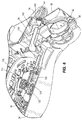
- FIG. 4A is a cross-sectional view of the vacuum cleaner of FIG. 1 taken along line 4 - 4 of FIG. 1 .
- FIG. 4B is a cross-sectional view of another embodiment of a vacuum cleaner.
- FIG. 5 is a partial cross-sectional view of the vacuum cleaner of FIG. 1 taken along line 5 - 5 of FIG. 2 , with portions removed.
- FIG. 6 is a partial cross-sectional view of the vacuum cleaner of FIG. 1 , with portions removed.
- FIG. 7 is a cross-sectional view of the vacuum cleaner of FIG. 1 taken along line 7 - 7 of FIG. 4 , with portions removed.
- FIG. 1 illustrates a vacuum cleaner 10 .
- the vacuum cleaner 10 includes a cord reel assembly 14 arranged on a front side 18 of a handle assembly 22 .
- the cord reel assembly 14 includes a housing 24 , a cord 26 and a cord reel 30 that is switchable between a first state, in which the cord reel 30 winds the cord 26 , and a second state, in which the cord reel 30 does not wind the cord 26 .
- an actuator 34 is arranged on a rear side 38 of the handle assembly 22 and is moveable between a first position and a second position. Movement of the actuator 34 from the first position to the second position switches the cord reel 30 from the second state to the first state.
- the vacuum cleaner 10 includes a foot 42 including a suction opening 46 .
- the vacuum cleaner 10 further includes a suction motor 50 that receives power when the cord 26 is plugged into an AC power source, and a dirt collection chamber 54 with an air treatment member in fluid communication with the suction opening 46 and the suction source 50 .
- the handle assembly 22 includes a grip 56 , and is pivotally coupled to the foot 42 for movement about a first pivot axis 68 between an upright position and an inclined position.
- the handle assembly 22 defines a longitudinal axis 62 .
- the vacuum cleaner 10 also includes a steering assembly 64 coupled between the handle assembly 22 and the foot 42 , the steering assembly 64 defining a second pivot axis of rotation 76 that is transverse to the first pivot axis 68 , as shown in FIGS. 4A and 4B .
- the handle assembly 22 is rotatable about the second pivot axis of rotation 76 relative to the foot 42 .
- the steering assembly 64 includes a neck 72 that defines the second pivot axis of rotation 76 about which the handle assembly 22 is rotatable relative to the foot 42 .
- the handle assembly 22 includes a collar 80 rotatably coupled to the neck 72 , such that the handle assembly 22 is rotatable about the axis of rotation 76 via the collar 80 rotating about the neck 72 .
- the axis of rotation 76 is transverse to the first pivot axis 68 and is formed at an acute angle ⁇ relative to the longitudinal axis 62 of the handle assembly 22 .
- the suction motor 50 is arranged in a motor housing 78 between the handle assembly 22 and the foot 42 .
- the first pivot axis 68 may extend through the motor housing 78 as shown in FIG. 4A .
- the motor housing 78 may be formed as a part of the steering assembly 64 or may be formed as a part of the handle assembly 22 .
- the suction motor 50 could be arranged elsewhere on the vacuum cleaner 10 .
- the vacuum cleaner 10 includes an air path made up of a dirty air path 82 that couples the suction opening 46 to the dirt collection chamber 54 and a clean air path 92 that fluidly couples the dirt collection chamber 54 to the suction motor 50 , as described in further detail below.
- the dirty air path 82 flows from the suction opening 46 of the foot 42 and through a conduit 84 to an air inlet 88 of the dirt collection chamber 54 .
- the dirty air path 82 is arranged between the suction opening 46 and the dirt collection chamber 54 and fluidly couples the dirt collection chamber 54 to the suction opening 46 .
- the conduit 84 is a flexible hose but in other embodiments, the conduit 84 can be something besides a hose.
- the clean air path 92 includes a first channel 96 extending through a spine 100 of the handle assembly 22 , a second channel 104 extending through the neck 72 of steering assembly 64 , and a third channel 108 extending through the steering assembly 64 to the suction motor 50 .
- the air After passing through the motor 50 , the air is exhausted through an air outlet, which may include a plurality of exhaust vents 160 on the steering assembly 64 .
- the clean air path 92 fluidly couples the dirt collection chamber 54 to the suction motor 50 .
- the longitudinal axis 62 may extend through a portion of the first channel 96 .
- the dirt collection chamber 54 includes the air treatment member, which may include one or more cyclones, one or more filters, a bag filter, or a combination of cyclone and filter as desired. After dust and debris is separated from the air stream, the air leaves the dirt collection chamber 54 to the first channel 96 of the clean air path 92 .
- the air treatment member includes a cyclonic separator and a filter (not shown).
- FIGS. 1, 2 and 4A illustrates the motor 50 in the clean air path 92 . However, in other embodiments the motor 50 may be in the dirty air path 82 .
- a different steering assembly 109 includes a pin 110 arranged in a steering portion 111 coupling the handle assembly 22 to the foot 42 .
- the handle assembly 22 is rotatable about the second pivot axis of rotation 76 via rotation about the pin 110 , which is arranged along the second pivot axis of rotation 76 .
- the dirty air path 82 passes from the suction opening 46 through the foot 42 and up through the spine 100 to the suction motor 50 (not shown in FIG. 4B ), which is arranged above the cord reel 30 .
- the suction motor 50 is arranged above the cord reel 30 and below the dirt collection chamber 54 .
- the cord reel 30 is arranged above the suction motor 50 and below the dirt collection chamber 54 .
- the first pivot axis 68 is defined by a pivot joint 114 on the foot 42 .
- the cord reel 30 is arranged under the dirt collection chamber 54 and above the steering assembly 64 .
- the cord reel 30 includes a frame 112 that is fixed to the handle assembly 22 and a spool 116 that holds the cord 26 and is rotatable with respect to the frame 112 about a cord reel axis 116 .
- the cord reel axis 116 is parallel to the longitudinal axis 62 of the handle assembly 22 .
- the cord reel axis 116 may be transverse to the longitudinal axis 62 .
- the cord 26 has been omitted for clarity in FIGS. 4A, 4B, 6 and 7 .
- the cord reel 30 includes a flat spiral spring 120 that turns the spool 116 in a first rotational direction with respect to the frame 112 .
- the cord reel 30 also includes a brake 124 that is moved to a braked position by a compression spring 128 or other mechanism.
- the brake 124 is moveable against the force of the spring 128 from the braked position to an unbraked position.
- the brake 124 has a pad 132 that is urged against the spool 116 when the brake 124 is in the braked position.
- the pressure of pad 132 against spool 116 applied via spring 128 , is sufficiently high that the spool 116 will not rotate absent an external force tugging on cord 26 .
- the cord reel 30 is in the second state, in which the cord reel 30 does not wind the cord.
- the pressure of pad 132 against spool 116 is sufficiently low that the spool 116 can rotate in a second rotational direction that is opposite the first rotational direction when an operator pulls on the cord 26 .
- the brake 124 is moved to the unbraked position, the pad 132 is spaced from the spool 116 , switching the cord reel 30 to the first state, in which the cord 26 is wound back onto the cord reel 30 .
- the spool 116 is rotated by the flat spiral spring 120 in the first rotational direction to wind the cord 26 onto the cord reel 30 .
- the vacuum cleaner 10 includes a linkage 136 coupled for movement of the brake 124 .
- the linkage 136 is positioned external to the first channel 96 of the clean air path 92 and extends around or along a side of the air path 92 .
- the linkage 136 includes two legs 140 that are arranged on either side of the first channel 96 .
- the linkage 136 may include one leg that is arranged on one side of the clean air path 92 .
- the linkage 136 is positioned external to the dirty air path 82 and extends around or along a side of the dirty air path 82 .
- the two legs 140 are arranged on either side of the dirty air path 82 .
- the linkage 136 may include one leg that is arranged on one side of the air dirty path 82 .
- the actuator 34 is pressed by a compression spring 144 to the first, extended position. As shown in FIGS. 2, 4A and 4B , the actuator 34 is located above the steering assembly 64 .
- the actuator 34 is a foot pedal, but in other embodiments the actuator can be a push button, a lever, a handle or other types of actuating members as desired for hand or foot operation.
- the actuator 34 is located on the rear side 38 of the handle assembly 22 and located centrally on a lower portion of the handle assembly 22 .
- the actuator 34 being located centrally does not necessarily mean the exact geometric center of the width of handle assembly 22 , but instead is a more general location positioned to provide access to an operator positioned to the rear side of the cleaner 10 . In the embodiments shown in FIGS.
- a user-manipulatable portion of the actuator 34 is positioned such that the air path extends between the user-manipulatable portion of the actuator 34 and the cord reel 30 .
- a contact portion 148 of the actuator 34 contacts the legs 140 of the linkage 136 to move linkage 136 , and thereby move brake 124 to the unbraked position, thus switching the cord reel 30 to the first state.
- the linkage 136 is integrally formed with and cantilevered from the actuator 34 .
- the operator grasps a plug end 152 of the cord 26 and pulls the plug end 152 from the handle assembly 22 , drawing the cord 26 through a cord port 156 on the handle assembly 64 .
- the spool 116 rotates in the second rotational direction, even while pad 132 is pressed against spool 116 . If the operator releases the cord 26 while extending it from the vacuum cleaner 10 , the cord 26 will not be wound back onto the spool 116 , because the cord reel 30 is in the second state.
- the pad 132 is pressed against spool 116 to prevent it from being rotated by the flat spiral spring 120 in the first rotational direction.
- the operator moves the handle assembly 22 about the first pivot axis 68 from the upright position to the inclined, operating position. While operating the vacuum cleaner 10 , the operator may rotate the handle assembly 22 about the pivot axis of rotation 76 via the collar 80 rotating about the neck 72 of the steering assembly 64 ( FIG. 4A ), or via the pin 110 within portion 111 ( FIG. 4B ). If the operator is standing behind the rear side 38 of the handle assembly 22 and rotates the handle assembly 22 clockwise about the second pivot axis of rotation 76 , the foot 42 will tend to turn to the right as it is being pushed forwardly. If the operator is standing behind the rear side 38 of the handle assembly 22 and rotates the handle assembly 22 counterclockwise about the second pivot axis of rotation 76 , the foot 42 will tend to turn to the left as it is being pushed in a forward direction.
- the operator unplugs the plug end 152 of the cord from the AC power source, such as the wall outlet.
- the operator then moves the actuator 34 from the first position to the second position thereby moving the linkage 136 and the brake 124 towards the cord reel axis 116 , such that pad 132 is separated from the spool 116 .
- the cord reel 30 is accordingly switched to the first state and the spool 116 is then rotated by the flat spiral spring 120 in the first rotational direction to retract the cord.
Abstract
Description
Claims (27)
Applications Claiming Priority (1)
| Application Number | Priority Date | Filing Date | Title |
|---|---|---|---|
| PCT/CN2018/096301 WO2020014922A1 (en) | 2018-07-19 | 2018-07-19 | Vacuum cleaner |
Publications (2)
| Publication Number | Publication Date |
|---|---|
| US20210228033A1 US20210228033A1 (en) | 2021-07-29 |
| US11197592B2 true US11197592B2 (en) | 2021-12-14 |
Family
ID=69164215
Family Applications (1)
| Application Number | Title | Priority Date | Filing Date |
|---|---|---|---|
| US17/055,779 Active US11197592B2 (en) | 2018-07-19 | 2018-07-19 | Vacuum cleaner |
Country Status (4)
| Country | Link |
|---|---|
| US (1) | US11197592B2 (en) |
| EP (1) | EP3784101A4 (en) |
| CN (1) | CN112384115B (en) |
| WO (1) | WO2020014922A1 (en) |
Cited By (5)
| Publication number | Priority date | Publication date | Assignee | Title |
|---|---|---|---|---|
| USD959075S1 (en) * | 2021-03-23 | 2022-07-26 | Bissell Inc. | Body for a floor cleaner |
| USD959076S1 (en) * | 2019-06-20 | 2022-07-26 | Sharkninja Operating Llc | Nozzle |
| USD962565S1 (en) * | 2017-05-17 | 2022-08-30 | Techtronic Floor Care Technology Limited | Floor cleaner |
| USD968043S1 (en) * | 2018-08-10 | 2022-10-25 | Sharkninja Operating Llc | Vacuum body of a vacuum cleaner |
| USD989427S1 (en) * | 2021-11-15 | 2023-06-13 | Bissell Inc. | Vacuum cleaner |
Citations (26)
| Publication number | Priority date | Publication date | Assignee | Title |
|---|---|---|---|---|
| US5361879A (en) * | 1993-08-11 | 1994-11-08 | Lin Yeong Hwa | Extension cord reel |
| JP2001070204A (en) | 1999-09-01 | 2001-03-21 | Sanyo Electric Co Ltd | Vacuum cleaner |
| US6363571B1 (en) | 1999-02-26 | 2002-04-02 | Pacific Steamex Cleaning Systems, Inc. | Convertible upright vacuum |
| US6574827B2 (en) | 2000-01-31 | 2003-06-10 | Matsushita Electric Industrial Co., Ltd. | Electric vacuum cleaner having increased stability and resistance against inadvertant falling over of the vacuum cleaner |
| US6779229B2 (en) | 2000-09-22 | 2004-08-24 | Daewoo Electronics Corporation | Versatile vacuum cleaner |
| CN201308448Y (en) | 2008-12-08 | 2009-09-16 | 金莱克电气股份有限公司 | Vertical-type vacuum cleaner |
| CN201505097U (en) | 2009-09-29 | 2010-06-16 | 刘志洪 | Winder with brake device for dust collector |
| US7739772B2 (en) | 2005-05-12 | 2010-06-22 | Lg Electronics, Inc. | Upright vacuum cleaner |
| US20100325832A1 (en) | 2009-06-25 | 2010-12-30 | Samsung Gwangju Electronics Co., Ltd. | Vacuum cleaner having power cord storage |
| US7992252B2 (en) | 2009-02-12 | 2011-08-09 | Lg Electronics Inc. | Vacuum cleaner |
| US20110209302A1 (en) * | 2010-02-04 | 2011-09-01 | Jinwook Seo | Vacuum cleaner |
| US20120167333A1 (en) | 2011-01-05 | 2012-07-05 | Hawkins Kyle A | Floor care apparatus with cord reel and nozzle assmebly |
| US20120167335A1 (en) * | 2011-01-05 | 2012-07-05 | Marsh Samuel A | Steerable upright vacuum cleaner |
| US20130117961A1 (en) * | 2010-12-01 | 2013-05-16 | Techtronic Floor Care Technology Limited | Wheel assembly for a vacuum cleaner |
| CN203042123U (en) | 2011-12-07 | 2013-07-10 | 夏普株式会社 | Longitudinal electric dust collector |
| CN203861135U (en) | 2014-05-14 | 2014-10-08 | 宁波德昌电机制造有限公司 | Dust collector provided with HEPA (High-Efficiency Particulate Air) filter structure |
| CN203861145U (en) | 2014-05-14 | 2014-10-08 | 宁波德昌电机制造有限公司 | Dust collector |
| CN203898202U (en) | 2014-05-30 | 2014-10-29 | 创科地板护理技术有限公司 | Vacuum cleaner |
| US20150093973A1 (en) | 2013-09-27 | 2015-04-02 | Black & Decker Inc. | Compact vacuum |
| CN104736033A (en) | 2013-04-22 | 2015-06-24 | 创科地板护理技术有限公司 | Vacuum cleaner filter housing |
| CN204722973U (en) | 2015-05-20 | 2015-10-28 | Ac(澳门离岸商业服务)有限公司 | For the vacuum cleaning tool of vacuum cleaner |
| CN106998976A (en) | 2014-10-23 | 2017-08-01 | 创科实业有限公司 | Switching valve for vacuum cleaner |
| US20170290482A1 (en) | 2015-12-10 | 2017-10-12 | Jiangsu Midea Cleaning Appliances Co., Ltd. | Clutch device for upright vacuum cleaner and upright vacuum cleaner having same |
| CN108065862A (en) | 2016-11-17 | 2018-05-25 | 百得有限公司 | Vacuum cleaner |
| CN108135416A (en) | 2015-08-05 | 2018-06-08 | 创科(澳门离岸商业服务)有限公司 | Dust catcher and bearing assembly |
| US20190059673A1 (en) * | 2017-08-28 | 2019-02-28 | Bissell Homecare, Inc. | Vacuum cleaner |
Family Cites Families (2)
| Publication number | Priority date | Publication date | Assignee | Title |
|---|---|---|---|---|
| DE102008022321A1 (en) * | 2008-04-30 | 2009-11-05 | Alfred Kärcher Gmbh & Co. Kg | vacuum cleaner |
| GB2549148B (en) * | 2016-04-08 | 2018-08-15 | Dyson Technology Ltd | A wand and hose assembly for a vacuum cleaner |
-
2018
- 2018-07-19 WO PCT/CN2018/096301 patent/WO2020014922A1/en unknown
- 2018-07-19 EP EP18926727.1A patent/EP3784101A4/en not_active Withdrawn
- 2018-07-19 CN CN201880094572.7A patent/CN112384115B/en active Active
- 2018-07-19 US US17/055,779 patent/US11197592B2/en active Active
Patent Citations (32)
| Publication number | Priority date | Publication date | Assignee | Title |
|---|---|---|---|---|
| US5361879A (en) * | 1993-08-11 | 1994-11-08 | Lin Yeong Hwa | Extension cord reel |
| US6363571B1 (en) | 1999-02-26 | 2002-04-02 | Pacific Steamex Cleaning Systems, Inc. | Convertible upright vacuum |
| JP2001070204A (en) | 1999-09-01 | 2001-03-21 | Sanyo Electric Co Ltd | Vacuum cleaner |
| US6574827B2 (en) | 2000-01-31 | 2003-06-10 | Matsushita Electric Industrial Co., Ltd. | Electric vacuum cleaner having increased stability and resistance against inadvertant falling over of the vacuum cleaner |
| US6588051B2 (en) | 2000-01-31 | 2003-07-08 | Matsushita Electric Industrial Co., Ltd. | Electric vacuum cleaner having a structure for facilitating the manufacturability thereof |
| US6678916B2 (en) | 2000-01-31 | 2004-01-20 | Matsushita Electric Industrial Co., Ltd. | Vacuum cleaner hose unit having a hose fitting with a coupling protrusion |
| US6779229B2 (en) | 2000-09-22 | 2004-08-24 | Daewoo Electronics Corporation | Versatile vacuum cleaner |
| US7739772B2 (en) | 2005-05-12 | 2010-06-22 | Lg Electronics, Inc. | Upright vacuum cleaner |
| CN201308448Y (en) | 2008-12-08 | 2009-09-16 | 金莱克电气股份有限公司 | Vertical-type vacuum cleaner |
| US8528163B2 (en) | 2009-02-12 | 2013-09-10 | Lg Electronics Inc. | Vacuum cleaner |
| US8881343B2 (en) | 2009-02-12 | 2014-11-11 | Lg Electronics Inc. | Vacuum cleaner |
| US7992252B2 (en) | 2009-02-12 | 2011-08-09 | Lg Electronics Inc. | Vacuum cleaner |
| US20100325832A1 (en) | 2009-06-25 | 2010-12-30 | Samsung Gwangju Electronics Co., Ltd. | Vacuum cleaner having power cord storage |
| CN201505097U (en) | 2009-09-29 | 2010-06-16 | 刘志洪 | Winder with brake device for dust collector |
| US20110209302A1 (en) * | 2010-02-04 | 2011-09-01 | Jinwook Seo | Vacuum cleaner |
| US20160073843A1 (en) | 2010-02-04 | 2016-03-17 | Lg Electronics Inc. | Vacuum cleaner |
| US9265392B2 (en) | 2010-02-04 | 2016-02-23 | Lg Electronics Inc. | Vacuum cleaner |
| US20130117961A1 (en) * | 2010-12-01 | 2013-05-16 | Techtronic Floor Care Technology Limited | Wheel assembly for a vacuum cleaner |
| US20120167333A1 (en) | 2011-01-05 | 2012-07-05 | Hawkins Kyle A | Floor care apparatus with cord reel and nozzle assmebly |
| US20120167335A1 (en) * | 2011-01-05 | 2012-07-05 | Marsh Samuel A | Steerable upright vacuum cleaner |
| CN203042123U (en) | 2011-12-07 | 2013-07-10 | 夏普株式会社 | Longitudinal electric dust collector |
| CN104736033A (en) | 2013-04-22 | 2015-06-24 | 创科地板护理技术有限公司 | Vacuum cleaner filter housing |
| US20150093973A1 (en) | 2013-09-27 | 2015-04-02 | Black & Decker Inc. | Compact vacuum |
| CN203861145U (en) | 2014-05-14 | 2014-10-08 | 宁波德昌电机制造有限公司 | Dust collector |
| CN203861135U (en) | 2014-05-14 | 2014-10-08 | 宁波德昌电机制造有限公司 | Dust collector provided with HEPA (High-Efficiency Particulate Air) filter structure |
| CN203898202U (en) | 2014-05-30 | 2014-10-29 | 创科地板护理技术有限公司 | Vacuum cleaner |
| CN106998976A (en) | 2014-10-23 | 2017-08-01 | 创科实业有限公司 | Switching valve for vacuum cleaner |
| CN204722973U (en) | 2015-05-20 | 2015-10-28 | Ac(澳门离岸商业服务)有限公司 | For the vacuum cleaning tool of vacuum cleaner |
| CN108135416A (en) | 2015-08-05 | 2018-06-08 | 创科(澳门离岸商业服务)有限公司 | Dust catcher and bearing assembly |
| US20170290482A1 (en) | 2015-12-10 | 2017-10-12 | Jiangsu Midea Cleaning Appliances Co., Ltd. | Clutch device for upright vacuum cleaner and upright vacuum cleaner having same |
| CN108065862A (en) | 2016-11-17 | 2018-05-25 | 百得有限公司 | Vacuum cleaner |
| US20190059673A1 (en) * | 2017-08-28 | 2019-02-28 | Bissell Homecare, Inc. | Vacuum cleaner |
Non-Patent Citations (2)
| Title |
|---|
| Chinese Patent Office Action for Application No. 201880094572.7 dated Aug. 20, 2021 (11 pages including statement of relevance). |
| International Search Report and Written Opinion for Application No. PCT/CN2018/096301 dated Apr. 18, 2019 (9 pages). |
Cited By (5)
| Publication number | Priority date | Publication date | Assignee | Title |
|---|---|---|---|---|
| USD962565S1 (en) * | 2017-05-17 | 2022-08-30 | Techtronic Floor Care Technology Limited | Floor cleaner |
| USD968043S1 (en) * | 2018-08-10 | 2022-10-25 | Sharkninja Operating Llc | Vacuum body of a vacuum cleaner |
| USD959076S1 (en) * | 2019-06-20 | 2022-07-26 | Sharkninja Operating Llc | Nozzle |
| USD959075S1 (en) * | 2021-03-23 | 2022-07-26 | Bissell Inc. | Body for a floor cleaner |
| USD989427S1 (en) * | 2021-11-15 | 2023-06-13 | Bissell Inc. | Vacuum cleaner |
Also Published As
| Publication number | Publication date |
|---|---|
| EP3784101A4 (en) | 2022-01-05 |
| EP3784101A1 (en) | 2021-03-03 |
| US20210228033A1 (en) | 2021-07-29 |
| CN112384115B (en) | 2023-03-28 |
| WO2020014922A1 (en) | 2020-01-23 |
| CN112384115A (en) | 2021-02-19 |
Similar Documents
| Publication | Publication Date | Title |
|---|---|---|
| US11197592B2 (en) | Vacuum cleaner | |
| AU2006207353B2 (en) | Surface treating appliance | |
| US8607412B2 (en) | Cleaning appliance | |
| US8671511B2 (en) | Surface treating appliance | |
| JP5179554B2 (en) | Surface treatment appliance | |
| US8769765B2 (en) | Surface treating appliance | |
| AU2004243218B2 (en) | A cleaning head | |
| KR100879080B1 (en) | Cleaner head for a vacuum cleaner | |
| US9009913B2 (en) | Surface treating appliance | |
| JP4977918B2 (en) | Surface treatment appliance | |
| JP5042350B2 (en) | Surface treatment appliance | |
| JP2011083614A (en) | Surface treating electric appliance | |
| JP2011083612A (en) | Surface treating appliance | |
| KR102481702B1 (en) | Cleaning head for surface treatment apparatus having at least one stabilizer and surface treatment apparatus having the same | |
| AU2018102200A4 (en) | Vacuum cleaner | |
| JP4069179B2 (en) | Electric vacuum cleaner | |
| JP2023173750A (en) | Nozzle and working machine | |
| JP2005224417A (en) | Vacuum cleaner | |
| KR20050057800A (en) | An equipment of the cord reel in vacuum cleaner |
Legal Events
| Date | Code | Title | Description |
|---|---|---|---|
| AS | Assignment |
Owner name: TECHTRONIC FLOOR CARE TECHNOLOGY LIMITED, VIRGIN ISLANDS, BRITISH Free format text: ASSIGNMENT OF ASSIGNORS INTEREST;ASSIGNOR:TTI (MACAO COMMERCIAL OFFSHORE) LIMITED;REEL/FRAME:054435/0001 Effective date: 20191217 Owner name: TTI (MACAO COMMERCIAL OFFSHORE) LIMITED, MACAU Free format text: ASSIGNMENT OF ASSIGNORS INTEREST;ASSIGNORS:TECHTRONIC (SUZHOU) COMMERCIAL CONSULTING CO., LTD.;ZHOU, RONG;KHALIL, DAVID;REEL/FRAME:054377/0482 Effective date: 20180713 |
|
| FEPP | Fee payment procedure |
Free format text: ENTITY STATUS SET TO UNDISCOUNTED (ORIGINAL EVENT CODE: BIG.); ENTITY STATUS OF PATENT OWNER: LARGE ENTITY |
|
| STPP | Information on status: patent application and granting procedure in general |
Free format text: NON FINAL ACTION MAILED |
|
| STPP | Information on status: patent application and granting procedure in general |
Free format text: RESPONSE TO NON-FINAL OFFICE ACTION ENTERED AND FORWARDED TO EXAMINER |
|
| STPP | Information on status: patent application and granting procedure in general |
Free format text: NOTICE OF ALLOWANCE MAILED -- APPLICATION RECEIVED IN OFFICE OF PUBLICATIONS |
|
| STPP | Information on status: patent application and granting procedure in general |
Free format text: NOTICE OF ALLOWANCE MAILED -- APPLICATION RECEIVED IN OFFICE OF PUBLICATIONS |
|
| AS | Assignment |
Owner name: TECHTRONIC FLOOR CARE TECHNOLOGY LIMITED, VIRGIN ISLANDS, BRITISH Free format text: ASSIGNMENT OF ASSIGNORS INTEREST;ASSIGNOR:TTI (MACAO COMMERCIAL OFFSHORE) LIMITED;REEL/FRAME:058037/0907 Effective date: 20191217 |
|
| STPP | Information on status: patent application and granting procedure in general |
Free format text: PUBLICATIONS -- ISSUE FEE PAYMENT RECEIVED |
|
| STPP | Information on status: patent application and granting procedure in general |
Free format text: PUBLICATIONS -- ISSUE FEE PAYMENT VERIFIED |
|
| STCF | Information on status: patent grant |
Free format text: PATENTED CASE |