US11192549B2 - Warning and adjusting the longitudinal speed of a motor vehicle based on the recognized road traffic lights - Google Patents
Warning and adjusting the longitudinal speed of a motor vehicle based on the recognized road traffic lights Download PDFInfo
- Publication number
- US11192549B2 US11192549B2 US16/760,823 US201816760823A US11192549B2 US 11192549 B2 US11192549 B2 US 11192549B2 US 201816760823 A US201816760823 A US 201816760823A US 11192549 B2 US11192549 B2 US 11192549B2
- Authority
- US
- United States
- Prior art keywords
- motor vehicle
- traffic light
- host motor
- speed
- acc
- Prior art date
- Legal status (The legal status is an assumption and is not a legal conclusion. Google has not performed a legal analysis and makes no representation as to the accuracy of the status listed.)
- Active, expires
Links
Images


Classifications
-
- B—PERFORMING OPERATIONS; TRANSPORTING
- B60—VEHICLES IN GENERAL
- B60W—CONJOINT CONTROL OF VEHICLE SUB-UNITS OF DIFFERENT TYPE OR DIFFERENT FUNCTION; CONTROL SYSTEMS SPECIALLY ADAPTED FOR HYBRID VEHICLES; ROAD VEHICLE DRIVE CONTROL SYSTEMS FOR PURPOSES NOT RELATED TO THE CONTROL OF A PARTICULAR SUB-UNIT
- B60W30/00—Purposes of road vehicle drive control systems not related to the control of a particular sub-unit, e.g. of systems using conjoint control of vehicle sub-units, or advanced driver assistance systems for ensuring comfort, stability and safety or drive control systems for propelling or retarding the vehicle
- B60W30/14—Adaptive cruise control
- B60W30/16—Control of distance between vehicles, e.g. keeping a distance to preceding vehicle
- B60W30/162—Speed limiting therefor
-
- B—PERFORMING OPERATIONS; TRANSPORTING
- B60—VEHICLES IN GENERAL
- B60W—CONJOINT CONTROL OF VEHICLE SUB-UNITS OF DIFFERENT TYPE OR DIFFERENT FUNCTION; CONTROL SYSTEMS SPECIALLY ADAPTED FOR HYBRID VEHICLES; ROAD VEHICLE DRIVE CONTROL SYSTEMS FOR PURPOSES NOT RELATED TO THE CONTROL OF A PARTICULAR SUB-UNIT
- B60W30/00—Purposes of road vehicle drive control systems not related to the control of a particular sub-unit, e.g. of systems using conjoint control of vehicle sub-units, or advanced driver assistance systems for ensuring comfort, stability and safety or drive control systems for propelling or retarding the vehicle
- B60W30/14—Adaptive cruise control
- B60W30/143—Speed control
- B60W30/146—Speed limiting
-
- B—PERFORMING OPERATIONS; TRANSPORTING
- B60—VEHICLES IN GENERAL
- B60W—CONJOINT CONTROL OF VEHICLE SUB-UNITS OF DIFFERENT TYPE OR DIFFERENT FUNCTION; CONTROL SYSTEMS SPECIALLY ADAPTED FOR HYBRID VEHICLES; ROAD VEHICLE DRIVE CONTROL SYSTEMS FOR PURPOSES NOT RELATED TO THE CONTROL OF A PARTICULAR SUB-UNIT
- B60W30/00—Purposes of road vehicle drive control systems not related to the control of a particular sub-unit, e.g. of systems using conjoint control of vehicle sub-units, or advanced driver assistance systems for ensuring comfort, stability and safety or drive control systems for propelling or retarding the vehicle
- B60W30/18—Propelling the vehicle
- B60W30/18009—Propelling the vehicle related to particular drive situations
- B60W30/181—Preparing for stopping
-
- B—PERFORMING OPERATIONS; TRANSPORTING
- B60—VEHICLES IN GENERAL
- B60W—CONJOINT CONTROL OF VEHICLE SUB-UNITS OF DIFFERENT TYPE OR DIFFERENT FUNCTION; CONTROL SYSTEMS SPECIALLY ADAPTED FOR HYBRID VEHICLES; ROAD VEHICLE DRIVE CONTROL SYSTEMS FOR PURPOSES NOT RELATED TO THE CONTROL OF A PARTICULAR SUB-UNIT
- B60W40/00—Estimation or calculation of non-directly measurable driving parameters for road vehicle drive control systems not related to the control of a particular sub unit, e.g. by using mathematical models
- B60W40/08—Estimation or calculation of non-directly measurable driving parameters for road vehicle drive control systems not related to the control of a particular sub unit, e.g. by using mathematical models related to drivers or passengers
-
- B—PERFORMING OPERATIONS; TRANSPORTING
- B60—VEHICLES IN GENERAL
- B60W—CONJOINT CONTROL OF VEHICLE SUB-UNITS OF DIFFERENT TYPE OR DIFFERENT FUNCTION; CONTROL SYSTEMS SPECIALLY ADAPTED FOR HYBRID VEHICLES; ROAD VEHICLE DRIVE CONTROL SYSTEMS FOR PURPOSES NOT RELATED TO THE CONTROL OF A PARTICULAR SUB-UNIT
- B60W50/00—Details of control systems for road vehicle drive control not related to the control of a particular sub-unit, e.g. process diagnostic or vehicle driver interfaces
- B60W50/08—Interaction between the driver and the control system
- B60W50/14—Means for informing the driver, warning the driver or prompting a driver intervention
- B60W50/16—Tactile feedback to the driver, e.g. vibration or force feedback to the driver on the steering wheel or the accelerator pedal
-
- G—PHYSICS
- G06—COMPUTING; CALCULATING OR COUNTING
- G06F—ELECTRIC DIGITAL DATA PROCESSING
- G06F17/00—Digital computing or data processing equipment or methods, specially adapted for specific functions
- G06F17/10—Complex mathematical operations
- G06F17/11—Complex mathematical operations for solving equations, e.g. nonlinear equations, general mathematical optimization problems
-
- G06K9/00825—
-
- G—PHYSICS
- G06—COMPUTING; CALCULATING OR COUNTING
- G06V—IMAGE OR VIDEO RECOGNITION OR UNDERSTANDING
- G06V20/00—Scenes; Scene-specific elements
- G06V20/50—Context or environment of the image
- G06V20/56—Context or environment of the image exterior to a vehicle by using sensors mounted on the vehicle
- G06V20/58—Recognition of moving objects or obstacles, e.g. vehicles or pedestrians; Recognition of traffic objects, e.g. traffic signs, traffic lights or roads
- G06V20/584—Recognition of moving objects or obstacles, e.g. vehicles or pedestrians; Recognition of traffic objects, e.g. traffic signs, traffic lights or roads of vehicle lights or traffic lights
-
- B—PERFORMING OPERATIONS; TRANSPORTING
- B60—VEHICLES IN GENERAL
- B60W—CONJOINT CONTROL OF VEHICLE SUB-UNITS OF DIFFERENT TYPE OR DIFFERENT FUNCTION; CONTROL SYSTEMS SPECIALLY ADAPTED FOR HYBRID VEHICLES; ROAD VEHICLE DRIVE CONTROL SYSTEMS FOR PURPOSES NOT RELATED TO THE CONTROL OF A PARTICULAR SUB-UNIT
- B60W40/00—Estimation or calculation of non-directly measurable driving parameters for road vehicle drive control systems not related to the control of a particular sub unit, e.g. by using mathematical models
- B60W40/08—Estimation or calculation of non-directly measurable driving parameters for road vehicle drive control systems not related to the control of a particular sub unit, e.g. by using mathematical models related to drivers or passengers
- B60W2040/0818—Inactivity or incapacity of driver
- B60W2040/0863—Inactivity or incapacity of driver due to erroneous selection or response of the driver
-
- B—PERFORMING OPERATIONS; TRANSPORTING
- B60—VEHICLES IN GENERAL
- B60W—CONJOINT CONTROL OF VEHICLE SUB-UNITS OF DIFFERENT TYPE OR DIFFERENT FUNCTION; CONTROL SYSTEMS SPECIALLY ADAPTED FOR HYBRID VEHICLES; ROAD VEHICLE DRIVE CONTROL SYSTEMS FOR PURPOSES NOT RELATED TO THE CONTROL OF A PARTICULAR SUB-UNIT
- B60W50/00—Details of control systems for road vehicle drive control not related to the control of a particular sub-unit, e.g. process diagnostic or vehicle driver interfaces
- B60W50/08—Interaction between the driver and the control system
- B60W50/14—Means for informing the driver, warning the driver or prompting a driver intervention
- B60W2050/143—Alarm means
-
- B—PERFORMING OPERATIONS; TRANSPORTING
- B60—VEHICLES IN GENERAL
- B60W—CONJOINT CONTROL OF VEHICLE SUB-UNITS OF DIFFERENT TYPE OR DIFFERENT FUNCTION; CONTROL SYSTEMS SPECIALLY ADAPTED FOR HYBRID VEHICLES; ROAD VEHICLE DRIVE CONTROL SYSTEMS FOR PURPOSES NOT RELATED TO THE CONTROL OF A PARTICULAR SUB-UNIT
- B60W50/00—Details of control systems for road vehicle drive control not related to the control of a particular sub-unit, e.g. process diagnostic or vehicle driver interfaces
- B60W50/08—Interaction between the driver and the control system
- B60W50/14—Means for informing the driver, warning the driver or prompting a driver intervention
- B60W2050/146—Display means
-
- B—PERFORMING OPERATIONS; TRANSPORTING
- B60—VEHICLES IN GENERAL
- B60W—CONJOINT CONTROL OF VEHICLE SUB-UNITS OF DIFFERENT TYPE OR DIFFERENT FUNCTION; CONTROL SYSTEMS SPECIALLY ADAPTED FOR HYBRID VEHICLES; ROAD VEHICLE DRIVE CONTROL SYSTEMS FOR PURPOSES NOT RELATED TO THE CONTROL OF A PARTICULAR SUB-UNIT
- B60W2540/00—Input parameters relating to occupants
- B60W2540/30—Driving style
-
- B—PERFORMING OPERATIONS; TRANSPORTING
- B60—VEHICLES IN GENERAL
- B60W—CONJOINT CONTROL OF VEHICLE SUB-UNITS OF DIFFERENT TYPE OR DIFFERENT FUNCTION; CONTROL SYSTEMS SPECIALLY ADAPTED FOR HYBRID VEHICLES; ROAD VEHICLE DRIVE CONTROL SYSTEMS FOR PURPOSES NOT RELATED TO THE CONTROL OF A PARTICULAR SUB-UNIT
- B60W2552/00—Input parameters relating to infrastructure
- B60W2552/40—Coefficient of friction
-
- B—PERFORMING OPERATIONS; TRANSPORTING
- B60—VEHICLES IN GENERAL
- B60W—CONJOINT CONTROL OF VEHICLE SUB-UNITS OF DIFFERENT TYPE OR DIFFERENT FUNCTION; CONTROL SYSTEMS SPECIALLY ADAPTED FOR HYBRID VEHICLES; ROAD VEHICLE DRIVE CONTROL SYSTEMS FOR PURPOSES NOT RELATED TO THE CONTROL OF A PARTICULAR SUB-UNIT
- B60W2555/00—Input parameters relating to exterior conditions, not covered by groups B60W2552/00, B60W2554/00
- B60W2555/60—Traffic rules, e.g. speed limits or right of way
Definitions
- the present invention relates in general to motor vehicle driver assistance, and in particular to warning and adjusting the longitudinal speed of a motor vehicle based on recognized traffic lights.
- the present invention finds application in any type of road motor vehicle, whether it is used for the transport of people, such as a car, a bus, a camper, etc., or for the transport of goods, such as an industrial motor vehicle (truck, road train, articulated truck, etc.) or light or medium-heavy commercial motor vehicle (van, closed vehicle, cabbed vehicle, etc.).
- an industrial motor vehicle truck, road train, articulated truck, etc.
- light or medium-heavy commercial motor vehicle van, closed vehicle, cabbed vehicle, etc.
- ADAS Advanced Driver Assistance Systems
- ADAS is one of the fastest growing segments in the automotive sector and is set to become increasingly popular in the coming years.
- the safety features of these systems are designed to avoid collisions and accidents by offering technologies which alert drivers to potential problems, or to avoid collisions by implementing safety measures and taking control of vehicles.
- the adaptive features can automate lighting, provide adaptive cruise control, automate braking, incorporate GPS/traffic information, connect smartphones, alert drivers of other vehicles to hazards, keep drivers in the correct lane, or show what is in blind spots.
- ADAS technology is based on camera/vision systems, sensory systems, automotive data networks, vehicle-to-vehicle (V2V) or vehicle-to-infrastructure (V2I) communication systems.
- V2V vehicle-to-vehicle
- V2I vehicle-to-infrastructure
- Next-generation ADAS systems will increasingly use wireless connectivity to add value to V2V or V2I communication.
- ACC Adaptive Cruise Control
- FIG. 1 shows a basic functional block diagram of the operations implemented by an automotive electronic control unit (ECU) to achieve prior art ACC functionality.
- ECU automotive electronic control unit
- the prior art ACC functionality operates based on various input quantities, including the current speed of the host motor vehicle, a cruise speed of the host motor vehicle set by the driver, the current relative speed and distance of the host motor vehicle relative to a leading motor vehicle, and the cruise distance of the host motor vehicle from a leading motor vehicle set by the driver through the setting of the so-called Headway Time, which represents, in terms of time rather than distance, the cruise distance that the driver of the host motor vehicle wishes to maintain relative to the leading motor vehicle, and which may not be less than a given value representing the safety distance, which, as is known, depends on the current speed of the host motor vehicle and on an average driver reaction time.
- the headway time is generally selectable by the driver of the host motor vehicle from a range of stored values resulting in a longer or shorter cruise distance of the host motor vehicle from a leading motor vehicle.
- a value of two seconds is generally considered sufficient for most drivers to prevent a rear-end collision with the leading motor vehicle.
- the ACC functionality is designed to operate in two different modes, a cruise mode, in which the current speed of the host motor vehicle is controlled to maintain a driver-settable cruise speed, and a follow mode, in which the current speed of the host motor vehicle is controlled to maintain a driver-settable cruise distance from a leading motor vehicle.
- the ACC functionality is designed to implement independent speed and distance controls that are selectable by a control logic designed to cause the switch from the cruise mode to the follow mode in response to the detection of a leading motor vehicle being below a predetermined distance from the host motor vehicle, and the return to the cruise mode in response to the detection of no leading motor vehicle being below a predetermined distance from the host motor vehicle.
- the ACC functionality operates based on control parameters or quantities, which include, inter alia, the host motor vehicle cruise speed and distance, as well as the acceleration/deceleration profile to be achieved by the host motor vehicle in order to maintain the cruise speed and distance, and are designed to have, under normal operating conditions, driver-settable nominal values, such as the cruise speed and distance, or pre-determined values stored in the ECU, such as the acceleration/deceleration profile, or computed based thereon.
- control parameters or quantities include, inter alia, the host motor vehicle cruise speed and distance, as well as the acceleration/deceleration profile to be achieved by the host motor vehicle in order to maintain the cruise speed and distance, and are designed to have, under normal operating conditions, driver-settable nominal values, such as the cruise speed and distance, or pre-determined values stored in the ECU, such as the acceleration/deceleration profile, or computed based thereon.
- FIG. 2 shows more detailed functional block diagrams for the speed and distance controls, which operate in a closed loop based on an error between a current value and a reference value of the controlled quantity (speed or distance) in order to eliminate the error between the two values and thus cause the current value to follow the reference value as closely as possible.
- US 2010/106413 A1 describes a configurable time-to-stop warning system of a motor vehicle to send an alarm warning to a driver of a motor vehicle relative to an imminent stop position from the motor vehicle along the transit road.
- Wireless messages transmitted from a remote entity to the vehicle are received.
- the messages contain information such as position data and other data affecting stopping of the vehicle.
- GPS data relating to instantaneous vehicle position in the road of travel is retrieved.
- a travel time until the vehicle reaches the stopping location is determined.
- a determination is made whether the driver has initiated braking.
- An advance notice period is determined for issuing a warning to the driver to decelerate the vehicle comprising the travel time plus a predetermined reaction time plus a selectable driver configured increment.
- a sensory warning to the driver of the vehicle is actuated if the advance notice period is less than the travel time and the driver has not initiated braking.
- US 2017/080930 A1 discloses a vehicle control apparatus applicable to a vehicle having at least one device configured to acquire a road situation information from an outside of the vehicle.
- the apparatus determines whether or not a particular situation regarding a vehicle traveling occurs on the basis of the road situation information.
- the particular situation being a situation that a driver of the vehicle should be alerted.
- the apparatus can perform an informing for alerting the driver and execute a cruise control for causing the vehicle to travel automatically without an operation of an acceleration operator of the vehicle.
- the apparatus performs the informing when the particular situation occurs, the cruise control is not executed and the acceleration operator is operated.
- the apparatus performs the informing when the particular situation occurs and the cruise control is executed, independently of whether or not the acceleration operator is operated.
- the Applicant has verified that automotive sensory systems are available including specific sensors that allow an automotive electronic control unit to recognise the approach of a motor vehicle to a road junction controlled by a traffic light system.
- the present invention aims to improve the ACC functionality by also integrating this technology so as to allow recognition of the approach of a motor vehicle to a junction controlled by a traffic light system in order to properly alert the driver of the motor vehicle and possibly to define when and how the ACC functionality can control the longitudinal speed of the motor vehicle so as to stop it comfortably and suitably to avoid the passage of the motor vehicle at the junction with a red or amber traffic light.
- an automotive adaptive cruise control system is provided, as claimed in the appended claims.
- FIGS. 1 and 2 show functional block diagrams of operations carried out by an automotive electronic control unit to implement a prior art ACC functionality.
- FIG. 3 shows functional block diagrams of operations carried out by an automotive electronic control unit to implement the ACC functionality according to the present invention.
- FIG. 4 shows a state diagram of a state machine describing the warning management in a motor vehicle approaching a road section regulated by a traffic light control.
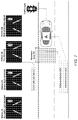
- FIGS. 5, 6 and 7 show information sequences displayed on a display of an automotive infotainment system of a motor vehicle approaching a road junction controlled by a traffic light system.
- FIG. 8 shows a functional block diagram of the estimation of control parameters used in the ACC functionality according to the present invention.
- FIG. 9 shows a functional block diagram of computation of two deceleration values used in the ACC functionality according to the present invention.
- FIG. 3 shows a basic functional block diagram of operations carried out by an automotive electronic control unit to implement the ACC functionality according to the present invention, which essentially provides for computing, in response to detecting, by a suitable sensor, a motor vehicle approaching a road junction controlled by a traffic light system (fixed or mobile), timings of warning and of any motor vehicle speed adjustment, taking account of the physical and environmental parameters measurable by the longitudinal control system of the motor vehicle.
- a traffic light system fixed or mobile
- the ACC functionality is designed to generate deceleration and engine torque requests, visual, acoustic and possibly also tactile warnings based on input data determined by the ECU based on the signals provided by the sensory system (radar, lidar, cameras) of the motor vehicle and/or stored in the ECU, and indicative of the following quantities: current speed of the host motor vehicle, current speed of a leading motor vehicle, current distance of the hot motor vehicle from a leading motor vehicle, adapted safety distance of the host motor vehicle, current distance of the host motor vehicle from a traffic light, estimation of the road adherence of the tyres of the host motor vehicle, as well as in the presence of the following indicators: visual, acoustic, and tactile warnings, and automatic slow-down.
- the deceleration and engine torque requests to the control system of the host motor are influenced by the current speed of the host motor vehicle, its distance from the traffic light, and an adapted safety distance DSA, which is settable by the driver of the host motor vehicle and is adjustable based on values learned during a manual driving mode and on the road adherence estimate.
- FIG. 4 shows a self-explanatory state diagram of a state machine describing the logical flow of warning a driver of a motor vehicle when the motor vehicle is approaching a road junction controlled by a traffic light system.
- the ACC functionality only alerts the driver of the motor vehicle approaching a road junction controlled by a traffic light system by means of a visual, acoustic, and/or tactile signal, while in an advanced version, the ACC functionality also progressively reduces the motor vehicle speed in order to (attempt to) stop it near the detected road traffic light system.
- the state machine when the automotive electronic control unit detects the presence of a traffic light system based on signals from an automotive sensory system, the state machine evolves to a “Detected Traffic Light” status [3], in which the driver of the host motor vehicle is immediately warned of the detection of the presence of a traffic light system ahead. If it is detected that the traffic light system is emitting a red or amber light signal, the state machine evolves to a “Pre-Warning” status [4], in which the reaction of the driver to the warning of the detection of the presence of a traffic light system ahead is verified.
- the reaction of the driver to the warning of the presence of the traffic light system is verified by computing (estimating) a driver reaction time TR based on the driving style, and two threshold distances SD 1 and SD 2 , one higher and one lower, in the manner described in detail below, which are used to cause the evolution or not of the state machine from the ‘Pre-Warning’ [4] to the ‘Active Warning Signal’ [5] status, in which the driver is warned of the need to intervene on the controls of the host motor vehicle to slow it down so as to stop it near the traffic light system.
- the motor vehicle is found not to have decreased its speed by more than a calibratable threshold speed, which may conveniently be a function of the motor vehicle speed at the moment of the detection of the traffic light system,
- the motor speed vehicle is higher than a minimum speed, e.g., 30 km/h,
- the distance of the vehicle from the detected traffic light system is less than the higher threshold distance SD 1 and the light signal emitted by the detected traffic light system is red, or the distance of the motor vehicle from the detected traffic light is between the higher and lower threshold distances SD 1 and SD 2 and the light emitted by the detected traffic light system is amber, and
- the state machine evolves from the ‘Pre-Warning’ [4] to the ‘Active Warning Signal’ [5] status, in which the driver is warned of the need to intervene on the controls of the motor vehicle to slow it down so as to stop it near the detected traffic light system.
- the ACC functionality can also intervene on the engine and the braking system of the host motor vehicle in order to progressively reduce the speed thereof in order to (attempt to) stop it near the detected traffic light system.
- FIGS. 5, 6 and 7 exemplarily show indications displayed on a display of the infotainment system of the host motor vehicle when approaching a road junction controlled by a traffic light system.
- FIG. 5 shows the information sequence displayed in the ‘Active Warning Signal’ status [5] when this is reached when a red traffic light is detected and at the end of the driver reaction time TR the host motor vehicle has not significantly decelerated and will therefore exceed the higher threshold distance SD 1 from the detected traffic light system.
- FIG. 6 shows the information sequence displayed in the ‘Active Warning Signal’ status [5] when this is reached when an amber traffic light is detected and at the end of the driver reaction time TR the host motor vehicle has not decelerated significantly, the higher distance threshold SD 1 will be exceeded but the lower distance threshold SD 2 from the detected traffic light system will not be exceeded.
- FIG. 7 shows the information sequence displayed in the ‘Active Warning Signal’ status [5] when this is reached when an amber traffic light is detected and at the end of the driver reaction time TR the host motor vehicle has not decelerated significantly, both the lower distance threshold SD 1 and the higher distance threshold SD 2 from the detected traffic light will be exceeded, and the subsequent evolution in the “Active Signalling End” status [6].
- FIG. 8 shows a functional block diagram implemented by the vehicle ECU of a driver-related parameter estimator designed to estimate the driver reaction time TR and the adapted safety distance SDA based on the driving style.
- the driver-related parameter estimator receives input data determined by the ECU based on signals from the sensory system (radar, lidar, cameras) of the host motor vehicle and/or stored in the ECU, and indicative of the following quantities: environmental quantities, automotive quantities, manual or automatic driving modes, which occur when the ACC functionality is disabled or, respectively, enabled, road adherence estimate, activation of the ACC functionality, and the distance of the host motor vehicle from a leading motor vehicle maintained by the driver during manual driving mode, i.e., when the ACC functionality is disabled.
- the sensory system radar, lidar, cameras
- the driver-related parameter estimator is designed to determine, based on the input data, and to store driving characteristics of the motor vehicle, such as the average distance (expressed in time) maintained relative to leading motor vehicles, average and maximum accelerations and decelerations and derived values, and then to estimate, based on the stored driving characteristics of the motor vehicle and on the control logic based on which switching from the cruise mode to the follow mode is caused and vice versa, the driver reaction time TR and the adapted safety distance SDA.
- the maximum attainable comfort deceleration D 1 and the maximum attainable deceleration D 2 are calculated as described below with reference to the functional block diagram illustrated in FIG. 9 .
- the road adherence of the host motor vehicle is first estimated based on input data determined by the ECU based on signals from the sensory system (radar, lidar, cameras) of the host motor vehicle and/or stored in the ECU, and indicative of the following quantities: current speed of the host motor vehicle, pressure of the tyres of the host motor vehicle, external temperature, wiper speed, rain rate measured by a rain sensor, a yaw speed of the host motor vehicle, the lateral acceleration of the host motor vehicle, the longitudinal acceleration of the host motor vehicle and the speed of the wheels of the host motor vehicle.
- radar radar, lidar, cameras
- the maximum comfort deceleration attainable D 1 and the maximum deceleration attainable D 2 are then computed based on two associated one-dimensional maps that are calibrated during a system calibration phase.
- the present invention allows the ACC functionality to be improved by signalling the approach of the motor vehicle to a road junction controlled by a traffic light system and controlling the longitudinal speed of the motor vehicle so as to make a comfortable stop of the motor vehicle that avoids the passage of the motor vehicle at the junction with a red or amber traffic light.
Abstract
-
- detect approaching to a traffic light and determine a light signal emitted thereby,
- signal to the driver the presence of the detected traffic light and the determined light signal,
- if the traffic light emits a red or amber light signal, estimating a driver reaction time, determining a higher threshold distance and a lower threshold distance from the traffic light, and warning the driver of the host vehicle of the need to slow it down if, after the driver reaction time has elapsed:
- i) the host motor vehicle has not decreased its speed by more than a calibratable threshold,
- ii) the current speed of the host vehicle is higher than a minimum speed,
- iii) either the distance of the host vehicle from the traffic light is lower than the higher threshold distance and the light signal emitted by the traffic light is red, or the distance of the host vehicle from the traffic light is between the higher and lower threshold distances and the light signal emitted by the traffic light is amber, and
- iv) a service brake of the host vehicle is unoperated.
Description
SD1=(motor vehicle speed)/(2·D1)
SD2=(motor vehicle speed)/(2·D2)
where D1 and D2 are the maximum attainable comfort deceleration and, respectively, the maximum attainable deceleration that are functions of a road adherence estimate and are dependent on the functional parameters of the host motor vehicle and on environmental parameters.
Claims (6)
SD1=(motor vehicle speed)2/(2·D1)
SD2=(motor vehicle speed)2/(2·D2)
Applications Claiming Priority (3)
| Application Number | Priority Date | Filing Date | Title |
|---|---|---|---|
| IT201700128738 | 2017-11-10 | ||
| IT102017000128738 | 2017-11-10 | ||
| PCT/IB2018/058838 WO2019092658A1 (en) | 2017-11-10 | 2018-11-09 | Warning and adjusting the longitudinal speed of a motor vehicle based on the recognized road traffic lights |
Publications (2)
| Publication Number | Publication Date |
|---|---|
| US20210221370A1 US20210221370A1 (en) | 2021-07-22 |
| US11192549B2 true US11192549B2 (en) | 2021-12-07 |
Family
ID=61868579
Family Applications (1)
| Application Number | Title | Priority Date | Filing Date |
|---|---|---|---|
| US16/760,823 Active 2039-01-22 US11192549B2 (en) | 2017-11-10 | 2018-11-09 | Warning and adjusting the longitudinal speed of a motor vehicle based on the recognized road traffic lights |
Country Status (3)
| Country | Link |
|---|---|
| US (1) | US11192549B2 (en) |
| EP (1) | EP3707045B1 (en) |
| WO (1) | WO2019092658A1 (en) |
Cited By (2)
| Publication number | Priority date | Publication date | Assignee | Title |
|---|---|---|---|---|
| US20220292958A1 (en) * | 2021-03-11 | 2022-09-15 | Toyota Jidosha Kabushiki Kaisha | Intersection control system, intersection control method, and non-transitory storage medium |
| US20220314999A1 (en) * | 2021-03-31 | 2022-10-06 | GM Global Technology Operations LLC | Systems and methods for intersection maneuvering by vehicles |
Families Citing this family (6)
| Publication number | Priority date | Publication date | Assignee | Title |
|---|---|---|---|---|
| JP7379033B2 (en) | 2019-09-12 | 2023-11-14 | 日産自動車株式会社 | Driving support method and driving support device |
| CN110949384B (en) * | 2019-11-20 | 2021-10-22 | 中国第一汽车股份有限公司 | Cruise control state display method and device and vehicle |
| CN111862635B (en) * | 2020-02-28 | 2022-08-09 | 重庆长安汽车股份有限公司 | Traffic signal lamp-based vehicle speed control method and device and automobile |
| US11396305B2 (en) * | 2020-07-30 | 2022-07-26 | Toyota Research Institute, Inc. | Systems and methods for improving driver warnings during automated driving |
| CN114655205A (en) * | 2022-04-06 | 2022-06-24 | 杨桂蝉 | Speed regulation prompting method in driving process |
| US20230326343A1 (en) * | 2022-04-08 | 2023-10-12 | Aptiv Technologies Limited | Interior Vehicle Alerting Based on an Object of Interest and an Environment of a Host Vehicle |
Citations (10)
| Publication number | Priority date | Publication date | Assignee | Title |
|---|---|---|---|---|
| US20060271265A1 (en) * | 2005-05-31 | 2006-11-30 | Nissan Technical Center North America, Inc. | Devices, systems and methods for prohibition of acceleration for cooperative speed control system |
| US20100106413A1 (en) | 2008-10-24 | 2010-04-29 | Gm Global Technology Operations, Inc. | Configurable vehicular time to stop warning system |
| US20120146811A1 (en) | 2010-12-14 | 2012-06-14 | Institute For Information Industry | Driving assisting system, method and computer readable storage medium for storing thereof |
| US20140240114A1 (en) * | 2011-11-01 | 2014-08-28 | Volkswagen Aktiengesellschaft | Method for outputting alert messages of a driver assistance system and associated driver assistance system |
| US20140309864A1 (en) * | 2013-04-15 | 2014-10-16 | Flextronics Ap, Llc | Configurable Dash Display Based on Detected Location and Preferences |
| WO2015093823A1 (en) | 2013-12-16 | 2015-06-25 | 엘지전자 주식회사 | Vehicle driving assistance device and vehicle equipped with same |
| US9305460B1 (en) | 2013-10-28 | 2016-04-05 | John Justine Aza | Roadway warning light detector and method of warning a motorist |
| US20160318490A1 (en) | 2015-04-28 | 2016-11-03 | Mobileye Vision Technologies Ltd. | Systems and methods for causing a vehicle response based on traffic light detection |
| US20170080930A1 (en) | 2015-09-18 | 2017-03-23 | Toyota Jidosha Kabushiki Kaisha | Vehicle control apparatus |
| US20170101107A1 (en) | 2015-10-08 | 2017-04-13 | Volkswagen Ag | Method for determining the activity of a driver of a motor vehicle and the adaptive response time and a corresponding assistance system |
-
2018
- 2018-11-09 US US16/760,823 patent/US11192549B2/en active Active
- 2018-11-09 WO PCT/IB2018/058838 patent/WO2019092658A1/en active Search and Examination
- 2018-11-09 EP EP18815341.5A patent/EP3707045B1/en active Active
Patent Citations (10)
| Publication number | Priority date | Publication date | Assignee | Title |
|---|---|---|---|---|
| US20060271265A1 (en) * | 2005-05-31 | 2006-11-30 | Nissan Technical Center North America, Inc. | Devices, systems and methods for prohibition of acceleration for cooperative speed control system |
| US20100106413A1 (en) | 2008-10-24 | 2010-04-29 | Gm Global Technology Operations, Inc. | Configurable vehicular time to stop warning system |
| US20120146811A1 (en) | 2010-12-14 | 2012-06-14 | Institute For Information Industry | Driving assisting system, method and computer readable storage medium for storing thereof |
| US20140240114A1 (en) * | 2011-11-01 | 2014-08-28 | Volkswagen Aktiengesellschaft | Method for outputting alert messages of a driver assistance system and associated driver assistance system |
| US20140309864A1 (en) * | 2013-04-15 | 2014-10-16 | Flextronics Ap, Llc | Configurable Dash Display Based on Detected Location and Preferences |
| US9305460B1 (en) | 2013-10-28 | 2016-04-05 | John Justine Aza | Roadway warning light detector and method of warning a motorist |
| WO2015093823A1 (en) | 2013-12-16 | 2015-06-25 | 엘지전자 주식회사 | Vehicle driving assistance device and vehicle equipped with same |
| US20160318490A1 (en) | 2015-04-28 | 2016-11-03 | Mobileye Vision Technologies Ltd. | Systems and methods for causing a vehicle response based on traffic light detection |
| US20170080930A1 (en) | 2015-09-18 | 2017-03-23 | Toyota Jidosha Kabushiki Kaisha | Vehicle control apparatus |
| US20170101107A1 (en) | 2015-10-08 | 2017-04-13 | Volkswagen Ag | Method for determining the activity of a driver of a motor vehicle and the adaptive response time and a corresponding assistance system |
Non-Patent Citations (2)
| Title |
|---|
| International Preliminary Report on Patentability issued in PCT/IB2018/058838 dated Oct. 30, 2019. |
| International Search Report and Written Opinion of the International Searching Authority issued in PCT/IB2018/058838 dated Feb. 27, 2019; ISA/SE. |
Cited By (3)
| Publication number | Priority date | Publication date | Assignee | Title |
|---|---|---|---|---|
| US20220292958A1 (en) * | 2021-03-11 | 2022-09-15 | Toyota Jidosha Kabushiki Kaisha | Intersection control system, intersection control method, and non-transitory storage medium |
| US20220314999A1 (en) * | 2021-03-31 | 2022-10-06 | GM Global Technology Operations LLC | Systems and methods for intersection maneuvering by vehicles |
| US11827223B2 (en) * | 2021-03-31 | 2023-11-28 | GM Global Technology Operations LLC | Systems and methods for intersection maneuvering by vehicles |
Also Published As
| Publication number | Publication date |
|---|---|
| WO2019092658A1 (en) | 2019-05-16 |
| EP3707045A1 (en) | 2020-09-16 |
| US20210221370A1 (en) | 2021-07-22 |
| EP3707045B1 (en) | 2021-04-28 |
Similar Documents
| Publication | Publication Date | Title |
|---|---|---|
| US11192549B2 (en) | Warning and adjusting the longitudinal speed of a motor vehicle based on the recognized road traffic lights | |
| US11173898B2 (en) | Driver assistance system for a motor vehicle | |
| EP3707046B1 (en) | Adjusting the longitudinal motion control of a host motor vehicle based on the estimation of the travel trajectory of a leading motor vehicle | |
| US10053067B2 (en) | Vehicle safety assist system | |
| JP6600001B2 (en) | How to control the distance between vehicles | |
| US10214215B2 (en) | Emergency vehicle control device | |
| US10286912B2 (en) | Emergency vehicle control device | |
| US9783201B2 (en) | Method and device for an overtaking assistant | |
| US8396642B2 (en) | Adaptive cruise control system | |
| JP6407431B2 (en) | In order to give a warning to the driver of the host vehicle or to autonomously control the host vehicle in response to the output indicating the vehicle approaching suddenly from the rear or the output indicating the vehicle approaching extremely rapidly from the rear Lane assist system and method | |
| US20170101102A1 (en) | Vehicle Safety System | |
| JP5163991B2 (en) | Vehicle speed control method in complex traffic situations | |
| US20170341652A1 (en) | Vehicle Control System | |
| US20100094509A1 (en) | System for Reducing The Braking Distance of a Vehicle | |
| CN106564502B (en) | method and device for determining the adaptive response time of a driver of a motor vehicle | |
| US10464420B2 (en) | Emergency vehicle control device | |
| JP2013543811A (en) | Method for detecting critical driving situations of trucks or passenger cars and method for avoiding collisions | |
| KR20120067762A (en) | The collision avoidance apparatus using low-speed and close-range collision avoidance algorithm for active safety | |
| CN109070852B (en) | Emergency braking system for a vehicle and method for controlling an emergency braking system | |
| US10279808B2 (en) | Adaptive cruise control system with speed based mode | |
| KR20170071272A (en) | Rear collision warning control method and apparatus | |
| JP5007167B2 (en) | Vehicle travel control device | |
| CN108382401B (en) | Highway driving assistance device, driving assistance method, and vehicle | |
| JP4831509B2 (en) | Collision warning method in automobile | |
| EP4015326A1 (en) | Vehicle control system, vehicle and method |
Legal Events
| Date | Code | Title | Description |
|---|---|---|---|
| FEPP | Fee payment procedure |
Free format text: ENTITY STATUS SET TO UNDISCOUNTED (ORIGINAL EVENT CODE: BIG.); ENTITY STATUS OF PATENT OWNER: LARGE ENTITY |
|
| STPP | Information on status: patent application and granting procedure in general |
Free format text: DOCKETED NEW CASE - READY FOR EXAMINATION |
|
| STPP | Information on status: patent application and granting procedure in general |
Free format text: NOTICE OF ALLOWANCE MAILED -- APPLICATION RECEIVED IN OFFICE OF PUBLICATIONS |
|
| AS | Assignment |
Owner name: C.R.F. SOCIETA' CONSORTILE PER AZIONI, ITALY Free format text: ASSIGNMENT OF ASSIGNORS INTEREST;ASSIGNOR:LANFRANCO, CLAUDIO;REEL/FRAME:057788/0862 Effective date: 20211005 |
|
| STPP | Information on status: patent application and granting procedure in general |
Free format text: PUBLICATIONS -- ISSUE FEE PAYMENT VERIFIED |
|
| STCF | Information on status: patent grant |
Free format text: PATENTED CASE |