US11190819B2 - Video transmission system - Google Patents
Video transmission system Download PDFInfo
- Publication number
- US11190819B2 US11190819B2 US16/645,909 US201716645909A US11190819B2 US 11190819 B2 US11190819 B2 US 11190819B2 US 201716645909 A US201716645909 A US 201716645909A US 11190819 B2 US11190819 B2 US 11190819B2
- Authority
- US
- United States
- Prior art keywords
- transmitter
- packets
- sequence numbers
- rtp
- video
- Prior art date
- Legal status (The legal status is an assumption and is not a legal conclusion. Google has not performed a legal analysis and makes no representation as to the accuracy of the status listed.)
- Active
Links
Images


Classifications
-
- H—ELECTRICITY
- H04—ELECTRIC COMMUNICATION TECHNIQUE
- H04N—PICTORIAL COMMUNICATION, e.g. TELEVISION
- H04N21/00—Selective content distribution, e.g. interactive television or video on demand [VOD]
- H04N21/20—Servers specifically adapted for the distribution of content, e.g. VOD servers; Operations thereof
- H04N21/23—Processing of content or additional data; Elementary server operations; Server middleware
- H04N21/242—Synchronisation processes, e.g. processing of PCR [Programme Clock References]
-
- H—ELECTRICITY
- H04—ELECTRIC COMMUNICATION TECHNIQUE
- H04L—TRANSMISSION OF DIGITAL INFORMATION, e.g. TELEGRAPHIC COMMUNICATION
- H04L1/00—Arrangements for detecting or preventing errors in the information received
- H04L1/08—Arrangements for detecting or preventing errors in the information received by repeating transmission, e.g. Verdan system
-
- H—ELECTRICITY
- H04—ELECTRIC COMMUNICATION TECHNIQUE
- H04L—TRANSMISSION OF DIGITAL INFORMATION, e.g. TELEGRAPHIC COMMUNICATION
- H04L1/00—Arrangements for detecting or preventing errors in the information received
- H04L1/22—Arrangements for detecting or preventing errors in the information received using redundant apparatus to increase reliability
-
- H—ELECTRICITY
- H04—ELECTRIC COMMUNICATION TECHNIQUE
- H04L—TRANSMISSION OF DIGITAL INFORMATION, e.g. TELEGRAPHIC COMMUNICATION
- H04L65/00—Network arrangements, protocols or services for supporting real-time applications in data packet communication
- H04L65/60—Network streaming of media packets
- H04L65/65—Network streaming protocols, e.g. real-time transport protocol [RTP] or real-time control protocol [RTCP]
-
- H—ELECTRICITY
- H04—ELECTRIC COMMUNICATION TECHNIQUE
- H04L—TRANSMISSION OF DIGITAL INFORMATION, e.g. TELEGRAPHIC COMMUNICATION
- H04L65/00—Network arrangements, protocols or services for supporting real-time applications in data packet communication
- H04L65/60—Network streaming of media packets
- H04L65/75—Media network packet handling
- H04L65/762—Media network packet handling at the source
-
- H—ELECTRICITY
- H04—ELECTRIC COMMUNICATION TECHNIQUE
- H04L—TRANSMISSION OF DIGITAL INFORMATION, e.g. TELEGRAPHIC COMMUNICATION
- H04L65/00—Network arrangements, protocols or services for supporting real-time applications in data packet communication
- H04L65/60—Network streaming of media packets
- H04L65/75—Media network packet handling
- H04L65/764—Media network packet handling at the destination
-
- H—ELECTRICITY
- H04—ELECTRIC COMMUNICATION TECHNIQUE
- H04L—TRANSMISSION OF DIGITAL INFORMATION, e.g. TELEGRAPHIC COMMUNICATION
- H04L69/00—Network arrangements, protocols or services independent of the application payload and not provided for in the other groups of this subclass
- H04L69/16—Implementation or adaptation of Internet protocol [IP], of transmission control protocol [TCP] or of user datagram protocol [UDP]
-
- H—ELECTRICITY
- H04—ELECTRIC COMMUNICATION TECHNIQUE
- H04L—TRANSMISSION OF DIGITAL INFORMATION, e.g. TELEGRAPHIC COMMUNICATION
- H04L69/00—Network arrangements, protocols or services independent of the application payload and not provided for in the other groups of this subclass
- H04L69/30—Definitions, standards or architectural aspects of layered protocol stacks
- H04L69/32—Architecture of open systems interconnection [OSI] 7-layer type protocol stacks, e.g. the interfaces between the data link level and the physical level
- H04L69/322—Intralayer communication protocols among peer entities or protocol data unit [PDU] definitions
- H04L69/329—Intralayer communication protocols among peer entities or protocol data unit [PDU] definitions in the application layer [OSI layer 7]
-
- H—ELECTRICITY
- H04—ELECTRIC COMMUNICATION TECHNIQUE
- H04L—TRANSMISSION OF DIGITAL INFORMATION, e.g. TELEGRAPHIC COMMUNICATION
- H04L69/00—Network arrangements, protocols or services independent of the application payload and not provided for in the other groups of this subclass
- H04L69/40—Network arrangements, protocols or services independent of the application payload and not provided for in the other groups of this subclass for recovering from a failure of a protocol instance or entity, e.g. service redundancy protocols, protocol state redundancy or protocol service redirection
-
- H—ELECTRICITY
- H04—ELECTRIC COMMUNICATION TECHNIQUE
- H04N—PICTORIAL COMMUNICATION, e.g. TELEVISION
- H04N21/00—Selective content distribution, e.g. interactive television or video on demand [VOD]
- H04N21/20—Servers specifically adapted for the distribution of content, e.g. VOD servers; Operations thereof
- H04N21/23—Processing of content or additional data; Elementary server operations; Server middleware
- H04N21/24—Monitoring of processes or resources, e.g. monitoring of server load, available bandwidth, upstream requests
- H04N21/2402—Monitoring of the downstream path of the transmission network, e.g. bandwidth available
-
- H—ELECTRICITY
- H04—ELECTRIC COMMUNICATION TECHNIQUE
- H04N—PICTORIAL COMMUNICATION, e.g. TELEVISION
- H04N21/00—Selective content distribution, e.g. interactive television or video on demand [VOD]
- H04N21/40—Client devices specifically adapted for the reception of or interaction with content, e.g. set-top-box [STB]; Operations thereof
- H04N21/43—Processing of content or additional data, e.g. demultiplexing additional data from a digital video stream; Elementary client operations, e.g. monitoring of home network or synchronising decoder's clock; Client middleware
- H04N21/4302—Content synchronisation processes, e.g. decoder synchronisation
- H04N21/4305—Synchronising client clock from received content stream, e.g. locking decoder clock with encoder clock, extraction of the PCR packets
-
- H—ELECTRICITY
- H04—ELECTRIC COMMUNICATION TECHNIQUE
- H04N—PICTORIAL COMMUNICATION, e.g. TELEVISION
- H04N21/00—Selective content distribution, e.g. interactive television or video on demand [VOD]
- H04N21/60—Network structure or processes for video distribution between server and client or between remote clients; Control signalling between clients, server and network components; Transmission of management data between server and client, e.g. sending from server to client commands for recording incoming content stream; Communication details between server and client
- H04N21/63—Control signaling related to video distribution between client, server and network components; Network processes for video distribution between server and clients or between remote clients, e.g. transmitting basic layer and enhancement layers over different transmission paths, setting up a peer-to-peer communication via Internet between remote STB's; Communication protocols; Addressing
- H04N21/631—Multimode Transmission, e.g. transmitting basic layers and enhancement layers of the content over different transmission paths or transmitting with different error corrections, different keys or with different transmission protocols
-
- H—ELECTRICITY
- H04—ELECTRIC COMMUNICATION TECHNIQUE
- H04N—PICTORIAL COMMUNICATION, e.g. TELEVISION
- H04N21/00—Selective content distribution, e.g. interactive television or video on demand [VOD]
- H04N21/60—Network structure or processes for video distribution between server and client or between remote clients; Control signalling between clients, server and network components; Transmission of management data between server and client, e.g. sending from server to client commands for recording incoming content stream; Communication details between server and client
- H04N21/63—Control signaling related to video distribution between client, server and network components; Network processes for video distribution between server and clients or between remote clients, e.g. transmitting basic layer and enhancement layers over different transmission paths, setting up a peer-to-peer communication via Internet between remote STB's; Communication protocols; Addressing
- H04N21/643—Communication protocols
- H04N21/64322—IP
-
- H—ELECTRICITY
- H04—ELECTRIC COMMUNICATION TECHNIQUE
- H04N—PICTORIAL COMMUNICATION, e.g. TELEVISION
- H04N21/00—Selective content distribution, e.g. interactive television or video on demand [VOD]
- H04N21/80—Generation or processing of content or additional data by content creator independently of the distribution process; Content per se
- H04N21/85—Assembly of content; Generation of multimedia applications
- H04N21/854—Content authoring
- H04N21/8547—Content authoring involving timestamps for synchronizing content
-
- H—ELECTRICITY
- H04—ELECTRIC COMMUNICATION TECHNIQUE
- H04J—MULTIPLEX COMMUNICATION
- H04J3/00—Time-division multiplex systems
- H04J3/02—Details
- H04J3/06—Synchronising arrangements
- H04J3/0635—Clock or time synchronisation in a network
- H04J3/0638—Clock or time synchronisation among nodes; Internode synchronisation
- H04J3/0658—Clock or time synchronisation among packet nodes
- H04J3/0661—Clock or time synchronisation among packet nodes using timestamps
- H04J3/0667—Bidirectional timestamps, e.g. NTP or PTP for compensation of clock drift and for compensation of propagation delays
Definitions
- This disclosure relates to a video transmission system, and more specifically, to a video transmission system for setting the same RTP sequence numbers to the IP-packets including the same payloads among the redundant transmitters.
- RTP Real-time Transport Protocol
- the IP-packets may not be transmitted. In order to address this situation, it is well-known to make the transmission path redundant. Making the transmission path redundant allows for, in the case of failure of an active transmission path, transmitting the IP-packets by switching the IP-packets from the active transmission path to a backup transmission path, thereby avoiding the interruption of transmitting the IP-packets.
- the video signals are switched without any control, the corruption of videos are visible to a viewer. Therefore, in switching the IP-packets, it is necessary to switch the IP-packets seamlessly.
- SMPTE Society of Motion Picture and Television Engineers 2022-7 Standard specifies the transmission scheme for switching the IP-packets and transmitting the video signals.
- SMPTE2022-7 specifies that a transmission side (transmitter) transmits a plurality of IP-packets including the same payload data to a destination via a plurality of different transmission paths (Ethernet).
- FIG. 1 shows the packet transmission scheme according to SMPTE2022-7.
- a transmitter 1 and a receiver 2 are connected via a transmission path 4 (active) and a transmission path 5 (backup) over an IP-network 3 .
- the transmitter 1 receives input video signals (SDI signals, DVB-ASI signals or video and audio information contained in a payload in IP-packets received over Ethernet) transmitted from a broadcast station, encapsulate the input video signals into series of IP-packets (hereinafter referred to as “IP-packet stream”), duplicates the IP-packet (two IP-packet streams including the same payload data are generated by the duplication), and transmits the two IP-packet streams via the transmission paths 4 and 5 , respectively.
- IP-packet stream series of IP-packets
- the same RTP sequence numbers are set to the duplicated two IP-packet streams. Since the IP-packets are transmitted via the transmission paths 4 and 5 , respectively, different IP-headers, different MAC-headers, or different VLAN-tags, or all of them are set to the IP-packets, respectively.
- the receiver 2 receives the two IP-packet streams transmitted via the transmission paths 4 and 5 , respectively, and normally reconstructs the video signals based on the IP-packet stream transmitted via the transmission path 4 .
- the receiver 2 controls such that the delays in receiving the IP-packet stream via the transmission paths 4 and 5 match at a switching point by buffering the IP-packet streams in buffer memories 2 a and 2 b for controlling the delay times (delay buffer). Thereby, it is possible to switch the IP-packet stream without corrupting the videos.
- FIG. 1 shows that the transmission path 4 fails when the receiver 2 receives the IP-packet including the RTP sequence number “2”. In this case, the receiver 2 cannot receive the IP-packets including the RTP sequence number “3” or “4” via the transmission path 4 . On the other hand, the receiver 2 receives the IP-packets including the RTP sequence numbers “3” and “4” subsequent to receiving the IP-packet including the RTP sequence number “2” via the transmission path 5 .
- the receiver 2 When the receiver 2 reconstructs one IP-packet stream from the two IP-packet streams received via the transmission paths 4 and 5 , the receiver 2 detects that the IP-packet including the RTP sequence number “3” is not in the delay buffer in the transmission path 4 , and switches to the transmission path 5 . Thereby, it can avoid the packet loss and the corruption of the reconstructed video signals by reconstructing the IP-packet stream from the IP-packets including the RTP sequence numbers “3” and “4” in the delay buffer in the transmission path 5 . It can achieve the seamless video signal switching.
- the transmitter fails, it may not be possible to transmit the IP-packet streams via any of the two transmission paths. Accordingly, when it requires higher reliability, it is necessary to make the transmitter redundant (e.g. using a plurality of devices and/or cards).
- the transmitter redundant e.g. using a plurality of devices and/or cards.
- the video signals are reconstructed using the RTP sequence numbers, it is necessary to match the RTP sequence numbers among the plurality of redundant transmitters.
- there is no technique for matching the RTP sequence numbers among the plurality of transmitters It is not possible to make the transmitter redundant in the scheme of reconstructing the video signals based on the RTP sequence numbers.
- an example scheme of matching the RTP sequence numbers among the redundant transmitters includes exchanging the RTP sequence numbers among a plurality of transmitters for example.
- such scheme takes considerable time to exchange the RTP sequence numbers in transmitting uncompressed video data at high speed according to SMPTE2022-6, and increasing the overhead for the processes according to the protocol, and thus cannot be practical in existing technologies.
- the embodiment provides a video transmission system for setting the same RTP sequence numbers to the IP-packets including the same payloads among the redundant transmitters and transmitting the IP-packets over the IP-network without exchanging the RTP sequence numbers among the plurality of transmitters.
- the video transmission system includes a PTP grand master, a first transmitter configured to synchronize a time with the PTP grand master according to PTP, a second transmitter configured to synchronize a time with the PTP grand master according to PTP, and a receiver connected to the first transmitter and the second transmitter over an IP-network, wherein the first transmitter and the second transmitter respectively, receive video signals distributed from one video signal, divide the video signals into a plurality of IP-packets, calculate an initial value for RTP sequence numbers based on PTP timestamps in accordance with the synchronized time according to PTP, and set the RTP sequence numbers sequential from the initial value to a RTP sequence fields in the plurality of IP-packets respectively, the first transmitter sends to the receiver, the plurality of IP-packets set the RTP sequence numbers as first IP-packets via a first transmission path according to RTP, and the second transmitter sends to the receiver, the plurality of IP-packets set the RTP sequence numbers as second
- the video transmission system includes a first transmitter configured to receive video signals distributed from one video signal, divide the video signals into a plurality of first IP-packets, and send the plurality of first IP-packets via a first transmission path, a second transmitter configured to receive the distributed video signals, divide the video signals into a plurality of second IP-packets, and send the plurality of second IP-packets via a second transmission path, and a receiver connected to the first transmitter and the second transmitter over an IP-network, wherein the first transmitter, sets the sequence numbers as first RTP sequence numbers to RTP sequence fields in the plurality of first IP-packets respectively, send to the receiver, the plurality of first IP-packets set the first RTP sequence numbers via a first transmission path according to RTP, and issues an initialization instruction to the second transmitter at a predetermined timing, wherein the second transmitter, sets the sequence numbers as second RTP sequence numbers to RTP sequence fields in the plurality of second IP-packets respectively, send to
- each of the plurality of redundant transmitters can independently set the RTP sequence numbers to the IP-packets and transmit the IP-packets according to RTP without exchanging the RTP sequence numbers among the plurality of redundant transmitters.
- FIG. 1 shows a scheme for transmitting video signals according to SMPTE2022-7.
- FIG. 2 shows operations based on PTP performed in a video transmission system according to a first embodiment.
- FIG. 3 shows a configuration of a video transmission system according to a first embodiment.
- FIG. 4 shows a configuration of a transmitter according to a first embodiment.
- FIG. 5 shows a method of setting of RTP sequence numbers according to a first embodiment.
- FIG. 6 shows a configuration of a transmitter according to a second embodiment.
- FIG. 7 shows a method of setting of RTP sequence numbers according to a second embodiment.
- IEEE1588v2 specifies a time delivering method with high accuracy over a LAN (Local Area Network).
- a network according to PTP includes a PTP grand master and a PTP slave.
- the PTP grand master is generally implemented as hardware for using for example GPS signals with high accuracy, atomic clock signals, or BB (Black Burst) signals for synchronizing video signals as a reference clock source.
- the PTP slave synchronizes a time with the PTP grand master.
- the PTP grand master 201 sends a Announce message to the PTP slave 202 , and a relation between the PTP grand master 201 and the PTP slave 202 is established (step S 201 ).
- the PTP grand master 201 sends a Sync message to the PTP slave 202 (step S 202 ).
- the Sync message includes a time t 1 at which it was sent.
- a time t 2 at which it was received is recorded.
- the PTP slave 202 sends a Delay_Req message to the PTP slave 202 (step S 203 ).
- the Delay_Req message includes a time t 3 at which it was actually sent.
- the PTP grand master 201 sends a Delay_Resp message to the PTP slave 202 (step S 204 ).
- the Delay_Resp message includes a time t 4 at which it was actually received.
- the PTP slave 202 calculates a round trip delay times and an offset (time difference) between the times in the PTP grand master 201 and the PTP slave 202 .
- the PTP slave 202 maintains the time synchronization with the PTP grand master 201 by repeating the operations of PTP multiple times per second, smoothing the calculated offset values, and reflecting the offset values in the time information.
- the embodiment describes the operations of PTP in the one step clock and the E2E (End-to-End) delay mechanism.
- PTP also specifies the two step clock and the P2P (Peer-to-Peer) delay mechanism. Further time correction operations are performed, and the time synchronization with higher accuracy is achieved.
- the disclosure does not provide further detailed description.
- the video transmission system according to the embodiments operates according to the protocol such as SMPTE2022-2 (specifying the transmission of MPEG-2 transport streams (TS) over IP-network) and SMPTE2022-6 (specifying the transmission of media signals with high bit rate over IP-network). Also, it is assumed that the IP-packets are transmitted over the IP-network according to RTP (Real-time Transport Protocol)/UDP (User Datagram Protocol).
- RTP Real-time Transport Protocol
- UDP User Datagram Protocol
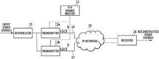
- the video transmission system comprises a distributor 11 , a PTP grand master 12 , a transmitter 13 a , a transmitter 13 b , and a receiver 14 .
- the transmitter 13 a , the transmitter 13 b , and the receiver 14 are connected over an IP-network 15 .
- a transmission path 16 is between the transmitter 13 a and the receiver 14
- a transmission path 17 is between the transmitter 13 b and the receiver 14 .
- the distributor 11 receives input video signals transmitted from a broadcast station for example, and distributes the input video signals to the transmitters 13 a and 13 b . That is, the distributor 11 duplicates the input video signals.
- the distributor 11 corresponds a distributor including a connector with a coaxial cable or optical fiber cable.
- the distributor 11 corresponds to an Ethernet switch.
- the PTP grand master 12 functions as the PTP grand master described in reference to FIG. 2 .
- the PTP grand master 12 synchronizes the time with the transmitters 13 a and 13 b .
- the grand master 12 may also synchronizes the time with the receiver 14 .
- Each of the transmitters 13 a and 13 b divides the input video signals distributed by the distributor 11 into IP-packets, and sends the IP-packets to the receiver 14 over the IP-network 15 .
- the transmitter 13 a sends to the receiver 14 , the IP-packets A that are divided and IP-packetized from the input video signals via the transmission path 16 according to RTP.
- the transmitter 13 b sends to the receiver 14 , the IP-packets B that are divided and IP-packetized from the input video signals via the transmission path 17 according to RTP. That is, each of the transmitters 13 a and 13 b sends the IP-packets including the same payloads via a separate transmission path.
- the same RTP sequence numbers are set to the IP-packets including the same payloads, and the details will be described hereinafter.
- Each of the transmitters 13 a and 13 b functions as a PTP slave, and synchronizes the time with the PTP grand master 12 according to PTP.
- the time corresponds to the SMPTE Epoch, that is, numerical values representing the time since the time 00:00:00 UTC on 1 Jan. 1970. That is, the transmitters 13 a and 13 b have the elapsed time with the accuracy within a nanosecond level error at the particular time point since the epoch.
- the embodiment employs the redundant system including two transmitters: the transmitter 13 a and the transmitter 13 b , the number of transmitters is not limited to two, and any number of transmitters are possible. Any number of transmission paths are possible according to the number of transmitters.
- the PTP grand master 12 may be also implemented in the transmitter 13 a , the transmitter 13 b , or a third transmitter (not shown) other than the transmitters 13 a and 13 b .
- the transmitter 13 b synchronizes the time with the transmitter 13 a .
- each of the transmitters 13 a and 13 b synchronizes the time with the third transmitter.
- the receiver 14 receives both of the IP-packets A sent via the transmission path 16 and the IP-packets B sent via the transmission path 17 . In the normal state, the receiver 14 reconstructs the video signals based on the IP-packets A (the IP-packets B are discarded).
- the receiver 14 switches from the IP-packets A to the IP-packets B to reconstruct the video signals based on the IP-packets B.
- the receiver 14 controls such that the timing of outputting the IP-packets including the same payloads is matched at the switching timing by buffering the IP-packets A and B in the delay buffers of the receiver 14 .
- the receiver 14 determines whether the IP-packets B includes the same payloads as those of the IP-packets A by referring the RTP sequence numbers set in the IP-packets A and B (specified in SMPTE2022-7).
- the transmitter 13 comprises a video signal receiving unit 131 , an IP-packet generating unit 132 , a PTP controlling unit 133 , a PTP timestamp counter 134 , a frame boundary determining unit 135 , a sequence number setting unit 136 , a sending unit 137 , a data network interface 138 , and a control network interface 139 .
- the video signal receiving unit 131 receives the video signals distributed by the distributor 11 .
- the IP-packet generating unit 132 generates the IP-packets from the received video signals according to RTP/UDP/IP for transmission over the IP-network 15 . More specifically, the IP-packet generating unit 132 generates the IP-packets by adding the RTP headers, the UDP headers, the IP headers, and/or the MAC headers.
- the PTP controlling unit 133 receives a PTP messages from the PTP grand master 12 via the control network interface 139 , and synchronizes the time with the PTP grand master 12 .
- the PTP timestamp counter 134 is incremented based on the time synchronization.
- the frame boundary determining unit 135 determines the video frame boundaries in the video signals inputted to the video signal receiving unit 131 . In the case that the video signals correspond to uncompressed video signals, the frame boundary determining unit 135 determines the video frame boundaries according to SMPTE424M, SMPTE292M, or SMPTE259M. In the case that the video signals are compatible to DVB-ASI, the frame boundary determining unit 135 determines the video frame boundaries by referring the payload unit start indicator in the TS header (when the video signals are compatible to SMPTE2022-s) in the IP-packets.
- the frame boundary determining unit 135 determines the video frame boundaries by referring the M (marker) bit in the RTP header in the IP-packets.
- the frame boundary determining unit 135 determines the video frame boundaries by referring the payload unit start indicator in the TS header.
- the sequence number setting unit 136 calculates the RTP sequence numbers based on the timestamps according to the increment of the PTP timestamp counter 134 .
- the calculated number is set to the RTP sequence number field (specified in RTP) in the RTP header of the first IP-packet in the video frame as a reference of the video frame boundary determined by the frame boundary determining unit 135 .
- a method of setting the RTP sequence numbers is described in reference to FIG. 5 .
- FIG. 5 shows a relation between the video frame boundaries of the IP-packets to be sent and the time.
- the horizontal axis corresponds to the time axis.
- one video frame includes a predetermined numbers of IP-packets.
- the sequence number setting unit 136 refers the timestamps according to the increment of the PTP timestamp counter 134 , and samples, when one seconds elapses, that is, the time is updated in seconds (at a second boundary (“second boundary 1 ” is shown in FIG. 5 )), the lower 16 bits of integer part of values calculated according to the equation (1)
- Sampling values ( SV ) ((32 CV ⁇ PSV )* VFN*IPN ) (2)
- 32 CVs are the 32 bits count values with seconds or more of the updated PTP timestamp counter 134
- PSVs are the values with seconds or more of the preset time
- VFN is the number of video frames per second
- IPN is the number of IP-packets per video frame.
- the preset time is common values between the transmitters 13 a and 13 b , and is the time since the SMPTE Epoch specified in SMPTE2059-1 in the embodiment in reference to FIG. 5 .
- the preset time is zero. It is noted that the above calculation may be easily implemented in a normal embedded processor or a logical circuit.
- the sequence number setting unit 136 sets as initial values the calculated RTP sequence numbers in IP-packets at which the video frame starts (video frame start IP-packet) as a reference of the video frame boundary (video frame boundary IP-packet) determined by the frame boundary determining unit 135 .
- the video frame boundary IP-packet means the last IP-packet per video frame.
- the second boundary is reached while the predetermined numbers of IP-packets in video frame N ⁇ 1 are generated.
- the values of the PTP timestamp counter 134 are ahead of the SMPTE Epoch by 16,890 days (46 years and one hundred days), one hour, two minutes, and three seconds at this time point. In this case, 32CV is 1,459,299,723 seconds.
- the format in which the video signals are sent is 1080P
- the size per video frame is 6,187,500 bytes.
- IPN is 4497.
- the frequencies in video frame is 59.94 Hz
- VFN is (60 Hz*1000/1001).
- PSV is zero
- the integer values on which the sampling values at the second boundary shown in FIG. 5 are calculated based are calculated according to the equation (2) 1,459,299,723*(60*1000/1001)*4497 (3)
- the following values can be obtained by rounding down the calculated values according to the equation (3) 393,354,896,363,496 (0x165C112DE4FE8 in hexadecimal number).
- the lower 16 bits of the calculated sampling values are 0x4FE8.
- the initial values “0x4FE8” are set to the RTP sequence number of the frame start IP-packet in the video frame N.
- the RTP sequence numbers added sequentially one are set to the IP-packets to be sent subsequently until the next “second boundary” (“second boundary 2 ” is shown in FIG. 5 ).
- Each of the transmitters 13 a and 13 b synchronizes the time with the accuracy within a nanosecond level error according to PTP. Therefore, the difference between the video signals distributed by the distributor 11 to the transmitters 13 a and 13 b is only the sum of delay times in the length of cables in which the video signals are delivered and the delay times in distributor 11 . If the difference between the timings of “second boundary” and video frame boundary is greater than the above difference between the delay times, for the IP-packets A and B including the same payloads sent via the transmission paths 16 and 17 , the calculated values according to the equation (1) are equal, and the IP-packets A and B include the same RTP sequence numbers.
- the calculated values according to the equation (1) may not be equal.
- the sampling values are not set to the RTP sequence numbers at the timing of “next second boundary” (“second boundary 2 ” as a reference of “second boundary 1 ” in FIG. 5 ), and it may be repeated to add one to the RTP sequence numbers sequentially.
- the calculated values according to the equation (1) are equal, and the IP-packets A and B can include the same RTP sequence numbers.
- the RTP sequence numbers are calculated at the timing of “second boundary”, and the calculated RTP sequence numbers are set at the start of video frame. After that, the RTP sequence numbers added sequentially one are set to the IP-packet to be sent subsequently until the next second boundary.
- each of the transmitters 13 a and 13 b can set the same RTP sequence numbers to the IP-packets including the same payloads without matching the RTP sequence numbers each other.
- calculating the sampling values and setting the RTP sequence numbers are performed at every second, that is, at the “second boundary”, it is merely illustrative and calculating and setting may be performed at any time interval such as 0.5 seconds or two seconds. It may also be possible to calculate the sampling values and set the RTP sequence numbers in response to the manual instruction via the GUI or command line input from the control network interfaces 139 of the transmitters 13 a and 13 b , or to the software program instruction, alternative to calculate the sampling values and set the RTP sequence numbers periodically at any time interval.
- the sending unit 137 sends packet-by-packet the IP-packet stream generated by the IP-packet generating unit 132 via the data network interface 138 over the IP-network 15 .
- each of the transmitters 13 a and 13 b can set the RTP sequence numbers to the IP-packets including the same payloads and send the IP-packets to the receiver 14 without matching the RTP sequence numbers each other.
- the receiver 14 when detecting that the active system fails, switches from the IP-packets A sent via the transmission path 16 to the IP-packets B sent via the transmission path 17 .
- the receiver 14 determines the IP-packets including the same payloads from the IP-packets A and B based on the RTP sequence numbers, and matches the timings of outputting the IP-packets including the same payloads by buffering the IP-packets according to SMPTE2077-7, thereby avoiding that the instantaneous interruption occurs in reconstructing the video signals (No instantaneous interruption (hit) is generally referred to as seamless or hitless). It is noted that the operations for the receiver to reconstruct the video signals based on the IP-packets are specified in SMPTE2022-7, and can be easily implemented in existing technique, and thus the disclosure does not provide further detailed description.
- the first embodiment provides the example of switching to the backup system when the transmission path of the active system fails, and embodiment is not limited to such example.
- the first embodiment may be applied to the case that the active system does not fail (e.g. transmission paths are not switched), and a portion of IP-packets A is lost.
- it can identify the IP-packets B including the same payloads as those in the IP-packets A from the IP-packets B sent via the transmission path 17 .
- the identified IP-packets B are used as alternative to the lost IP-packets A.
- FIG. 6 shows a configuration of a transmitter according to the second embodiment.
- the transmitter 13 a issues an initialization instruction to the transmitter 13 b at a predetermined timing, and the transmitter 13 b initializes the RTP sequence numbers at the same timing as the transmitter 13 a in response to the initialization instruction.
- the video transmission system according to the second embodiment is the same as that in the first embodiment except for the configuration of the transmitter.
- the transmitter according to the second embodiment comprises an initialization instructing unit 140 instead of the PTP controlling unit 133 and the PTP timestamp counter 134 .
- the initialization instructing unit 140 issues the initialization instruction to another transmitter (e.g. the transmitter 13 a issues to the transmitter 13 b ) in wait for a predetermined time.
- the initialization instruction may be issued in the dedicated UDP packet or the MAC frame for example.
- the initialization instruction may be issued in predetermined messages in the TCP/IP session established between the transmitters 13 a and 13 b . It is apparent that it can easily implement to issue the initialization instruction using other existing technique. Referring to FIG. 7 , a method of setting of the RTP sequence numbers is described.
- FIG. 7 shows a relation between the video frame boundaries of the IP-packets to be sent and the time.
- An upper part in FIG. 7 shows operations performed by the transmitter 13 a .
- a lower part in FIG. 7 shows operations performed by the transmitter 13 b.
- the initialization instructing unit 140 issues the initialization instruction to the transmitter 13 b in wait for the predetermined time (prohibition period for issuing initialization instruction).
- the initialization instructing unit 140 initializes the RTP sequence numbers with predetermined numbers.
- the initialization instructing unit 140 initializes the RTP sequence numbers with predetermined numbers.
- the predetermined numbers used by the transmitters 13 a and 13 b for initialization are the same numbers.
- the initialization instructing unit 140 of the transmitter 13 a waits for the predetermined time (prohibition period for issuing initialization instruction). This is because that if the initialization instruction is issued to the transmitter 13 b immediately after determining the video frame boundary, transmitter 13 b may incorrectly determine the video frame boundary for which the RTP sequence number is initialized due to the difference between the delay times in inputting the video signals to the transmitter 13 a and 13 b . As shown in FIG.
- the RTP sequence number is initialized for the first IP-packet in the video frame 2 , not for the first IP-packet in the video frame 3 , which leads to the mismatch of the IP-packets between the transmitters 13 a and 13 b .
- the mismatch can be avoided by making the prohibition period for issuing initialization instruction by the transmitter 13 a be greater than the difference between the delay times in inputting the video signals to the transmitters 13 a and 13 b.
- the transmitters 13 a and 13 b can initialize the RTP sequence numbers at the same timing after immediately determining the same subsequent video frame boundaries. After that, the RTP sequence numbers added sequentially one are set to the IP-packets to be sent subsequently. Therefore, each of the transmitters 13 a and 13 b can set the same sequence numbers to the IP-packets including the same payloads.
- the second embodiment it can match the RTP sequence numbers between the transmitters 13 a and 13 b without being compatible to PTP by the transmitter 13 a issuing the initialization instruction to the transmitter 13 b at a certain interval, thereby implementing the transmitters 13 a and 13 b with the configurations easier than those in the first embodiment.
- the prohibition period for issuing initialization instruction refers to the predetermined period until the subsequent video frame boundary since the video frame boundary is determined
- the prohibition period is not limited to the above example.
- the initialization instruction may waited to be issued until the predetermined numbers of IP-packets are sent since the video frame boundary is determined.
Landscapes
- Engineering & Computer Science (AREA)
- Signal Processing (AREA)
- Multimedia (AREA)
- Computer Networks & Wireless Communication (AREA)
- Computer Security & Cryptography (AREA)
- Data Exchanges In Wide-Area Networks (AREA)
- Two-Way Televisions, Distribution Of Moving Picture Or The Like (AREA)
Abstract
Description
Offset=(t2−t1)−(one way delay time)
(One way delay time)={(T2−T1)+(T4−T3)}/2 (1)
The
Sampling values (SV)=((32CV−PSV)*VFN*IPN) (2)
32 CVs are the 32 bits count values with seconds or more of the updated
1,459,299,723*(60*1000/1001)*4497 (3)
The following values can be obtained by rounding down the calculated values according to the equation (3)
393,354,896,363,496 (0x165C112DE4FE8 in hexadecimal number).
The lower 16 bits of the calculated sampling values are 0x4FE8.
-
- A IP-packet
- B IP-packet
- 16 transmission path
- 17 transmission path
Claims (6)
Applications Claiming Priority (1)
| Application Number | Priority Date | Filing Date | Title |
|---|---|---|---|
| PCT/JP2017/033319 WO2019053857A1 (en) | 2017-09-14 | 2017-09-14 | Video transmission system |
Publications (2)
| Publication Number | Publication Date |
|---|---|
| US20200280750A1 US20200280750A1 (en) | 2020-09-03 |
| US11190819B2 true US11190819B2 (en) | 2021-11-30 |
Family
ID=65722575
Family Applications (1)
| Application Number | Title | Priority Date | Filing Date |
|---|---|---|---|
| US16/645,909 Active US11190819B2 (en) | 2017-09-14 | 2017-09-14 | Video transmission system |
Country Status (2)
| Country | Link |
|---|---|
| US (1) | US11190819B2 (en) |
| WO (1) | WO2019053857A1 (en) |
Families Citing this family (13)
| Publication number | Priority date | Publication date | Assignee | Title |
|---|---|---|---|---|
| US12425357B2 (en) * | 2017-02-12 | 2025-09-23 | Mellanox Technologies Ltd. | Communication apparatus generating and eliminating redundant data packets |
| WO2021044560A1 (en) | 2019-09-04 | 2021-03-11 | ローランド株式会社 | Arpeggiator and program equipped with function therefor |
| WO2021044621A1 (en) * | 2019-09-06 | 2021-03-11 | ローランド株式会社 | Information processing method, information processing device, and program |
| US12493879B2 (en) | 2020-01-05 | 2025-12-09 | Ironvest, Inc. | User authentication and transaction verification via a shared video stream |
| US20210209606A1 (en) * | 2020-01-05 | 2021-07-08 | Obsecure Inc. | System, Device, and Method of User Authentication and Transaction Verification |
| US12548025B2 (en) * | 2020-01-05 | 2026-02-10 | Ironvest, Inc. | System, device, and method of transaction verification based on challenge and response messages |
| US12095655B2 (en) * | 2020-01-08 | 2024-09-17 | Nevion As | Redundant transmission system |
| WO2022013916A1 (en) * | 2020-07-13 | 2022-01-20 | 日本電信電話株式会社 | Transmission-side transport device, reception-side transport device, transmission-side transport device redundancy method, reception-side transport device redundancy method, program, and transport device |
| US11604751B1 (en) * | 2021-05-10 | 2023-03-14 | Xilinx, Inc. | Optimizing hardware design throughput by latency aware balancing of re-convergent paths |
| US11777628B2 (en) * | 2021-11-23 | 2023-10-03 | Ciena Corporation | Hitless protection for packet based digitized clock distribution |
| EP4228271B1 (en) * | 2022-02-09 | 2025-01-29 | EVS Broadcast Equipment SA | Media data transmission and processing system and method for operating such system |
| CN115314643B (en) * | 2022-07-28 | 2023-12-15 | 中央广播电视总台 | Method, system, equipment and storage medium for realizing net switching |
| US11838193B1 (en) * | 2022-12-16 | 2023-12-05 | Amazon Technologies, Inc. | Real-time load limit measurement for a plurality of nodes |
Citations (6)
| Publication number | Priority date | Publication date | Assignee | Title |
|---|---|---|---|---|
| JP2003174632A (en) | 2001-12-06 | 2003-06-20 | Kddi Corp | Synchronous video transmission equipment |
| JP2010109978A (en) | 2008-10-17 | 2010-05-13 | Thomson Licensing | Method for reception of signal, and corresponding transmission method |
| US20130003757A1 (en) * | 2011-06-30 | 2013-01-03 | Harman International Industries, Incorporated | Syntonized communication system |
| WO2014181381A1 (en) | 2013-05-10 | 2014-11-13 | ネクシオン株式会社 | Video data distributed transmission system |
| US20170070772A1 (en) * | 2015-09-09 | 2017-03-09 | Media Global Links Co., Ltd. | Video transmission system and video receiver |
| US20170264665A1 (en) * | 2014-09-30 | 2017-09-14 | British Telecommunications Public Limited Company | Managing streamed communication |
-
2017
- 2017-09-14 US US16/645,909 patent/US11190819B2/en active Active
- 2017-09-14 WO PCT/JP2017/033319 patent/WO2019053857A1/en not_active Ceased
Patent Citations (7)
| Publication number | Priority date | Publication date | Assignee | Title |
|---|---|---|---|---|
| JP2003174632A (en) | 2001-12-06 | 2003-06-20 | Kddi Corp | Synchronous video transmission equipment |
| JP2010109978A (en) | 2008-10-17 | 2010-05-13 | Thomson Licensing | Method for reception of signal, and corresponding transmission method |
| US20130003757A1 (en) * | 2011-06-30 | 2013-01-03 | Harman International Industries, Incorporated | Syntonized communication system |
| WO2014181381A1 (en) | 2013-05-10 | 2014-11-13 | ネクシオン株式会社 | Video data distributed transmission system |
| US20170264665A1 (en) * | 2014-09-30 | 2017-09-14 | British Telecommunications Public Limited Company | Managing streamed communication |
| US20170070772A1 (en) * | 2015-09-09 | 2017-03-09 | Media Global Links Co., Ltd. | Video transmission system and video receiver |
| JP2017055273A (en) | 2015-09-09 | 2017-03-16 | 株式会社メディアグローバルリンクス | Video transmission system and video receiver |
Non-Patent Citations (1)
| Title |
|---|
| SMPTE 2022-7 "Seamless Protection Switching" for DekTec network adapters, DekTec., Dec. 19, 2014, pp. 1-6. |
Also Published As
| Publication number | Publication date |
|---|---|
| US20200280750A1 (en) | 2020-09-03 |
| WO2019053857A1 (en) | 2019-03-21 |
Similar Documents
| Publication | Publication Date | Title |
|---|---|---|
| US11190819B2 (en) | Video transmission system | |
| US11122310B2 (en) | Video switching system | |
| EP2150062B1 (en) | Improved method, system and apparatus for synchronizing signals | |
| JP6796233B2 (en) | Video switching system | |
| EP3142377B1 (en) | Video transmission system and video receiver | |
| CA2684227C (en) | Improved method, system and apparatus for synchronizing signals | |
| US20200287644A1 (en) | Stream synchronization | |
| JP5902477B2 (en) | Delivery delay compensation for synchronous communication devices in packet-switched networks | |
| CN104581188A (en) | Method and apparatus for IP video signal synchronization | |
| JP6796234B2 (en) | Video transmission system | |
| Heiko et al. | Time synchronization of spatial separated areas for AV-production | |
| US20250211813A1 (en) | Method of streaming synchronized audio over a network | |
| JP7625773B1 (en) | Ancillary data inserter and program according to SMPTE ST2110 | |
| JP2025166728A (en) | Transmitting system, receiving system, and transmission system | |
| JP2024042198A (en) | Packet synchronization control device, packet synchronous reproduction device, packet synchronization control method, packet synchronous reproduction method, and program | |
| JP2013065958A (en) | Packet transmission system and method |
Legal Events
| Date | Code | Title | Description |
|---|---|---|---|
| AS | Assignment |
Owner name: MEDIA LINKS CO., LTD., JAPAN Free format text: ASSIGNMENT OF ASSIGNORS INTEREST;ASSIGNORS:NAKAMURA, KAZUNORI;NARITA, KAZUKI;REEL/FRAME:052067/0060 Effective date: 20200227 |
|
| FEPP | Fee payment procedure |
Free format text: ENTITY STATUS SET TO UNDISCOUNTED (ORIGINAL EVENT CODE: BIG.); ENTITY STATUS OF PATENT OWNER: LARGE ENTITY |
|
| STPP | Information on status: patent application and granting procedure in general |
Free format text: DOCKETED NEW CASE - READY FOR EXAMINATION |
|
| STPP | Information on status: patent application and granting procedure in general |
Free format text: NON FINAL ACTION MAILED |
|
| STPP | Information on status: patent application and granting procedure in general |
Free format text: RESPONSE TO NON-FINAL OFFICE ACTION ENTERED AND FORWARDED TO EXAMINER |
|
| STPP | Information on status: patent application and granting procedure in general |
Free format text: NOTICE OF ALLOWANCE MAILED -- APPLICATION RECEIVED IN OFFICE OF PUBLICATIONS |
|
| STPP | Information on status: patent application and granting procedure in general |
Free format text: PUBLICATIONS -- ISSUE FEE PAYMENT VERIFIED |
|
| STCF | Information on status: patent grant |
Free format text: PATENTED CASE |
|
| CC | Certificate of correction | ||
| FEPP | Fee payment procedure |
Free format text: ENTITY STATUS SET TO SMALL (ORIGINAL EVENT CODE: SMAL); ENTITY STATUS OF PATENT OWNER: SMALL ENTITY |
|
| MAFP | Maintenance fee payment |
Free format text: PAYMENT OF MAINTENANCE FEE, 4TH YR, SMALL ENTITY (ORIGINAL EVENT CODE: M2551); ENTITY STATUS OF PATENT OWNER: SMALL ENTITY Year of fee payment: 4 |