JP6796233B2 - Video switching system - Google Patents
Video switching system Download PDFInfo
- Publication number
- JP6796233B2 JP6796233B2 JP2016172759A JP2016172759A JP6796233B2 JP 6796233 B2 JP6796233 B2 JP 6796233B2 JP 2016172759 A JP2016172759 A JP 2016172759A JP 2016172759 A JP2016172759 A JP 2016172759A JP 6796233 B2 JP6796233 B2 JP 6796233B2
- Authority
- JP
- Japan
- Prior art keywords
- packet
- packets
- stream
- video signal
- transmitter
- Prior art date
- Legal status (The legal status is an assumption and is not a legal conclusion. Google has not performed a legal analysis and makes no representation as to the accuracy of the status listed.)
- Active
Links
- 230000005540 biological transmission Effects 0.000 claims description 81
- 230000001360 synchronised effect Effects 0.000 claims description 6
- 239000000872 buffer Substances 0.000 description 110
- 230000015654 memory Effects 0.000 description 30
- 238000000034 method Methods 0.000 description 16
- 230000007274 generation of a signal involved in cell-cell signaling Effects 0.000 description 14
- 238000012545 processing Methods 0.000 description 8
- 230000001934 delay Effects 0.000 description 7
- 230000006870 function Effects 0.000 description 7
- 238000006243 chemical reaction Methods 0.000 description 6
- 239000003550 marker Substances 0.000 description 2
- 238000004891 communication Methods 0.000 description 1
- 238000007796 conventional method Methods 0.000 description 1
- 238000012937 correction Methods 0.000 description 1
- 238000010586 diagram Methods 0.000 description 1
- 239000000835 fiber Substances 0.000 description 1
- 238000005259 measurement Methods 0.000 description 1
- 230000010076 replication Effects 0.000 description 1
- 230000008054 signal transmission Effects 0.000 description 1
Images


Description
本発明は、映像切替システムに関し、特に、IPパケット化された映像信号をシームレスに切り替える映像切替システムに関する。 The present invention relates to a video switching system, and more particularly to a video switching system that seamlessly switches an IP packetized video signal.
スポーツ中継での映像を競技場から放送用の中継センター、もしくは直接放送局に伝送する放送システム、または(基幹)放送局から他の放送局に映像信号をマルチキャストで伝送する映像伝送システムが知られている。このような映像信号を伝送する場合、その映像信号はIPパケットに変換されて、RTP(Real-time Transport Protocol)に従ってIPネットワークを経由して伝送されることが多い。RTPは、音声や動画などのデータ信号をリアルタイムに配信するためのデータ通信プロトコルである。 A broadcasting system that transmits video from a sports broadcast from a stadium to a broadcasting center or a direct broadcasting station, or a video transmission system that transmits a video signal from a (core) broadcasting station to another broadcasting station by multicast is known. ing. When such a video signal is transmitted, the video signal is often converted into an IP packet and transmitted via an IP network according to RTP (Real-time Transport Protocol). RTP is a data communication protocol for delivering data signals such as voice and moving images in real time.
上述したIPパケットを伝送する場合に使用される伝送経路に障害が発生した場合、IPパケットを伝送することができないことがある。このような事象に対処するために、伝送経路を冗長化することが一般的に行われている。伝送経路を冗長化することによって、現用系の伝送経路に障害が発生した場合に、予備系の伝送経路からのIPパケットに切り替えてIPパケットを伝送することができる。このような構成によって、IPパケットの伝送が中断されることを防止することができる。ここで、映像信号の場合、何ら制御をせずに切り替えを行うと、映像の乱れが視聴者の目に見えることになる。よって、上述したような切り替えを行う際に、シームレスな切り替えを行うことが要求される。 If a failure occurs in the transmission path used to transmit the IP packet described above, the IP packet may not be transmitted. In order to deal with such an event, it is common practice to make the transmission path redundant. By making the transmission path redundant, when a failure occurs in the transmission path of the active system, the IP packet can be transmitted by switching to the IP packet from the transmission path of the backup system. With such a configuration, it is possible to prevent the transmission of the IP packet from being interrupted. Here, in the case of a video signal, if the switching is performed without any control, the disturbance of the video becomes visible to the viewer. Therefore, seamless switching is required when switching as described above.
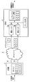
上述したIPパケットの切り替えを行うための映像信号の伝送方式に関する標準規格として、SMPTE(Society of Motion Picture and Television Engineers)2022−7が規定されている。SMPTE2022−7は、IPネットワーク上でIPパケットを送信する送信側(送信機)が、同一のペイロードデータを有する複数のIPパケットを複数の異なる伝送経路(イーサネット:登録商標)上で宛先に送信することを規定している。図1は、SMPTE2022−7に従ったパケット伝送の方式を示す。 SMPTE (Society of Motion Picture and Television Engineers) 2022-7 is defined as a standard for a video signal transmission method for switching IP packets as described above. In SMPTE2022-7, a transmitter (transmitter) that transmits an IP packet on an IP network transmits a plurality of IP packets having the same payload data to a destination on a plurality of different transmission paths (Ethernet: registered trademark). It stipulates that. FIG. 1 shows a packet transmission method according to SMPTE2022-7.
図1に示すように、送信機1と受信機2との間にはIPネットワーク3が存在し、伝送経路4(現用系)および伝送経路5(予備系)を介して両者が接続される。放送局などから伝送される入力映像信号(SDI信号、DVB−ASI信号、またはイーサネット経由で受信するIPパケット内のペイロードに含まれる映像および音声情報)を受信した送信機1は、入力映像信号を一連のIPパケット群(以下、「IPパケットストリーム」と呼ぶ)にカプセル化し、さらに各IPパケットを複製し(この複製によって同一のペイロードデータを有する2つのIPパケットストリームが生成される)、2つのIPパケットストリームを伝送経路4および伝送経路5のそれぞれを介して送信する。複製された2つのIPパケットには、同一のRTPシーケンス番号が設定される。ただし、2つのIPパケットは、伝送経路4および伝送経路5のそれぞれを通じて送信されるために、IPヘッダ、MACヘッダ、およびVLANタグの一部、または必要とあれば全てについて各々異なった値が設定される。受信機2は、伝送経路4および伝送経路5で送信された2つのIPパケットストリームをそれぞれ受信し、通常は、伝送経路4から受信したIPパケットストリームに基づいて、映像信号を再構築する。
As shown in FIG. 1, an
ここで、伝送経路4に障害が発生した場合、伝送経路5から受信したIPパケットに切り替える必要がある。この切り替え時に、伝送経路4から受信したIPパケットストリームおよび伝送経路5から受信したIPパケットストリームを、受信機2における遅延時間調整用のバッファメモリ(遅延バッファ)2aおよび2bによってそれぞれバッファリングすることによって、切り替え点での両系の遅延が同一となるように調整する。これにより、切り替え時に出力する映像を乱さずに切り替えることが可能となる。
Here, if a failure occurs in the
図1では、受信機2が、RTPシーケンス番号に「2」が設定されたIPパケットを受信した時点で、伝送経路4に障害が発生したことを示している。この場合、受信機2は、伝送経路4からはRTPシーケンス番号に「3」あるいは「4」が設定されたIPパケットを受信することができない。一方で、受信機2は、伝送経路5からはRTPシーケンス番号が「2」のIPパケットに引き続いて「3」および「4」のIPパケットを受信する。受信機2は、受信した2つのIPパケットストリームから1つのIPパケットストリームの構築を行う段階で、伝送経路4の遅延バッファにはRTPシーケンス番号が「3」のIPパケットが存在しないことを検出し、伝送経路5への切り替えを行う。そして、伝送経路5の遅延バッファが出力するRTPシーケンス番号が「3」および「4」のIPパケットをIPパケットストリームの構築に使用することによりパケットロスを発生させず、結果としての出力する再構築済み映像信号を乱すことはない。これにより、映像信号のシームレスな切り替えが実現される。
FIG. 1 shows that a failure has occurred in the
上述した方式でも、当然ながら、送信機が故障した場合は、2つの伝送経路のうちのいずれにおいてもIPパケットストリームを送信することができないことがある。従って、より高い信頼性が要求される場合には、(複数の筐体および/またはカードを使用することによって)送信機が冗長化されることが必要となる。ここで、SMPTE2022−7で規定された方式では、RTPシーケンス番号を使用して、映像信号を再構築しているので、冗長化された複数の送信機間でRTPシーケンス番号を合わせる必要がある。しかしながら、従来技術では、複数の送信機間でRTPシーケンス番号を合わせる技術が存在せず、RTPシーケンス番号に基づいて映像信号を再構築する方法では、送信機を冗長化することができなかった。 Even with the above method, of course, if the transmitter fails, it may not be possible to transmit the IP packet stream on either of the two transmission paths. Therefore, if higher reliability is required, the transmitter needs to be redundant (by using multiple enclosures and / or cards). Here, in the method specified by SMPTE2022-7, since the video signal is reconstructed by using the RTP sequence number, it is necessary to match the RTP sequence number between a plurality of redundant transmitters. However, in the prior art, there is no technique for matching RTP sequence numbers between a plurality of transmitters, and the method of reconstructing a video signal based on the RTP sequence numbers cannot make the transmitters redundant.
引用文献1は、ザッピングサービスにおいて、入力画像シーケンスの同一の画像が元になったデータを含む複数のRTPパケットに同一のタイムスタンプを持たせることによって、ザッピングサービスに収容された特定の個別の画像の、メインサービスデータシーケンスに対する位置を知ることができる動画エンコーダおよびデコーダを開示している。引用文献1では、同一の画像の複数のRTPパケットに同一のタイムスタンプを持たせているが、これは複数のRTPパケットに同じRTPシーケンス番号を持たせることと何ら変わりはなく、上述した課題を解決するものではない。
本発明は、このような問題に鑑みてなされたものであり、複数の送信機間でRTPシーケンス番号を合わせる必要なく、RTPに従って映像信号をIPネットワーク上で送信し、送信されたIPパケットを受信機側で切り替えることができる映像切替システムを提供することを目的とする。 The present invention has been made in view of such a problem, and it is not necessary to match RTP sequence numbers between a plurality of transmitters, a video signal is transmitted on an IP network according to RTP, and a transmitted IP packet is received. The purpose is to provide a video switching system that can be switched on the machine side.
上記の課題を解決するために、本発明に係る映像切替システムは、PTPグランドマスタと、前記PTPグランドマスタとPTPに従って時刻同期し、1つの映像信号から分配された映像信号を入力とする第1の送信機および第2の送信機と、前記第1の送信機および前記第2の送信機とIPネットワークを介して接続された受信機とを備え、前記第1の送信機および前記第2の送信機のそれぞれは、前記分配された映像信号を複数のIPパケットに分割する事でIPパケットストリームを作成し、前記PTPに従って時刻同期された時刻情報をベースにしたタイムスタンプを、前記IPパケットストリームにおけるIPパケットのそれぞれに設定し、前記第1の送信機は、前記IPパケットストリームを第1のIPパケットストリームとして、RTPに従って、第1の伝送経路を介して前記受信機に送信し、前記第2の送信機は、前記IPパケットストリームを第2のIPパケットストリームとして、RTPに従って、第2の伝送経路を介して前記受信機に送信し、前記受信機はIPパケットストリームにおけるタイムスタンプに基づいてシームレス切替えを行うことをすることを特徴とする。
In order to solve the above problems, the video switching system according to the present invention has a first method in which the PTP ground master and the PTP ground master are time-synchronized according to the PTP, and the video signal distributed from one video signal is input. The first transmitter and the second transmitter are provided with a transmitter and a second transmitter, and a receiver connected to the first transmitter and the second transmitter via an IP network. Each of the transmitters creates an IP packet stream by dividing the distributed video signal into a plurality of IP packets, and sets a time stamp based on the time information time-synchronized according to the PTP to the IP packet stream. The first transmitter transmits the IP packet stream as the first IP packet stream to the receiver via the first transmission path according to the RTP, and is set for each of the IP packets in the above. The
上記の課題を解決するために、本発明に係る別の映像切替システムは、第1の送信機と、第2の送信機と、前記第1の送信機および前記第2の送信機とIPネットワークを介して接続された受信機とを備え、前記第1の送信機は入力映像信号から第1のIPパケットストリームを作成して前記IPネットワークを介して前記受信機に送信し、前記第2の送信機は入力映像信号から第2のIPパケットストリームを作成して前記IPネットワークを介して前記受信機に送信し、前記受信機は、受信する前記第1および第2のIPパケットストリームから入力映像信号の映像フレーム境界を示すIPパケットを検出し、検出した前記入力映像信号の境界を示すIPパケットの位置とRTPシーケンス番号に基づいて前記第1のIPパケットストリームにおけるIPパケットと前記第2のIPパケットストリームにおけるIPパケットの位置とを対応付けすることにより異なったRTPシーケンス番号を有するIPパケットストリーム間のシームレス切替えを行うことを特徴とする。 In order to solve the above problems, another video switching system according to the present invention includes a first transmitter, a second transmitter, the first transmitter, the second transmitter, and an IP network. The first transmitter creates a first IP packet stream from the input video signal and transmits the first IP packet stream to the receiver via the IP network, and the second transmitter is provided with the receiver connected to the receiver. The transmitter creates a second IP packet stream from the input video signal and transmits it to the receiver via the IP network, and the receiver receives the input video from the first and second IP packet streams to be received. The IP packet indicating the boundary of the video frame of the signal is detected, and the IP packet in the first IP packet stream and the second IP are based on the position of the detected IP packet indicating the boundary of the input video signal and the RTP sequence number. It is characterized in that seamless switching between IP packet streams having different RTP sequence numbers is performed by associating with the position of the IP packet in the packet stream.
本発明に係る映像切替システムによれば、冗長化された複数の送信機がRTPシーケンス番号を合わせる必要なく、現用系に障害が発生した際にIPパケットのシームレスな切り替えが可能になる。 According to the video switching system according to the present invention, it is not necessary for a plurality of redundant transmitters to match RTP sequence numbers, and IP packets can be seamlessly switched when a failure occurs in the working system.
<第1の実施形態>
以下、図面を参照して、本発明の実施形態について説明する。図2は、本発明の第1の実施形態に係る映像切替システムが使用するPTP(Precision Time Protocol)の処理を示す図である。PTPは、IEEE(Institute of Electrical and Electronics Engineers)1588v2で規定された、ナノ秒のレベルでの誤差精度を実現する時刻同期プロトコルである。
<First Embodiment>
Hereinafter, embodiments of the present invention will be described with reference to the drawings. FIG. 2 is a diagram showing processing of PTP (Precision Time Protocol) used by the video switching system according to the first embodiment of the present invention. PTP is a time synchronization protocol that achieves error accuracy at the nanosecond level, as defined by the Institute of Electrical and Electronics Engineers (IEEE) 1588v2.
IEEE1588v2は、LAN(Local Area Network)経由での高精度な時刻の配信方法について規定している。PTPで時刻同期するネットワークは、PTPグランドマスタとPTPスレーブから構成される。PTPグランドマスタは、通常、高精度のGPS信号、電波時計信号あるいは映像信号の同期用のBB(Black Burst)信号などをリファレンスクロックのソースとして使用することができるハードウェアとして実装される。PTPスレーブはPTPグランドマスタとの間で時刻同期する。 IEEE1588v2 defines a highly accurate time distribution method via a LAN (Local Area Network). A network that synchronizes time with PTP is composed of a PTP grand master and a PTP slave. The PTP grand master is usually implemented as hardware that can use a high-precision GPS signal, a radio clock signal, a BB (Black Burst) signal for synchronizing a video signal, or the like as a reference clock source. The PTP slave synchronizes time with the PTP grand master.
図2に示すように、PTPグランドマスタ201がPTPスレーブ202にAnnounceメッセージを送信することによって、PTPグランドマスタ201とPTPスレーブ202との関係が確立される(ステップS201)。
As shown in FIG. 2, the relationship between the PTP
次に、PTPグランドマスタ201がPTPスレーブ202にSyncメッセージを送信する(ステップS202)。Syncメッセージには、メッセージの送信時刻(t1)が含まれ、PTPスレーブ202が受信すると到着時刻(t2)が記録される。
Next, the PTP
PTPスレーブ202がPTPグランドマスタ201にDelay_Reqメッセージを送信する(ステップS203)。Delay_Reqメッセージには、メッセージの送信時刻の実際の値(t3)が記録される。
The
次に、PTPグランドマスタ201がPTPスレーブ202にDelay_Respメッセージを送信する(ステップS204)。Delay_Respメッセージには、Delay_Reqメッセージの実際の到着時刻(t4)が記録される。
Next, the PTP
PTPスレーブ202は、t1、t2、t3、およびt4を使用して、往復の遅延時間とPTPグランドマスタ201の時刻とPTPスレーブ202の時刻とのオフセット(時間差)を算出する。片道の遅延時間が往復の遅延時間の半分であると仮定すると、PTPスレーブ202のオフセットは以下の式によって算出される。
PTPスレーブのクロックのオフセット=(t2−t1)−(片道の遅延時間)
(片道の遅延時間)={(T2−T1) + (T4−T3)} / 2
式1
PTPスレーブ202が上記の処理を1秒間に複数回繰り返し、処理結果のオフセット値の平滑化を行い時刻情報にフィードバックすることによって、PTPグランドマスタ201との時刻の同期が維持される。
The
PTP slave clock offset = (t2-t1)-(one-way delay time)
(One-way delay time) = {(T2-T1) + (T4-T3)} / 2
The
本説明は1ステップクロック(1−step clock)とE2Eディレイメカニズム (End−to−End delay mechanism)でのPTPの動作を説明したものである。 実際には、PTPでは2ステップクロック(2−step clock)、あるいはP2Pディレイメカニズム (Peer−to−Peer delay mechanism)の仕様も定義されており、さらなる補正などの処理が行われ、より誤差精度の高い時刻同期が実現されるが、本明細書では、これ以上の詳細な説明は行わない。 This description describes the operation of PTP with a 1-step clock (1-step clock) and an E2E delay mechanism (End-to-End delay mechanism). Actually, in PTP, the specifications of the 2-step clock (2-step clock) or the P2P delay mechanism (Peer-to-Peer delay mechanism) are also defined, and further correction and other processing are performed to improve the error accuracy. Although high time synchronization is achieved, no further details will be given herein.
次に、図3を参照して、本発明の第1の実施形態に係る映像切替システムの構成の例を説明する。本実施形態に係る映像切替システムは、SMPTE2022−2(IPネットワーク上でのMPEG−2トランスポートストリーム(TS)の伝送を規定)、SMPTE2022−6(IPネットワーク上での高ビットレートメディア信号の伝送を規定)などの、SMPTE2022で規定されたプロトコルに準拠することを前提とする。また、IPネットワーク上でのIPパケットの伝送においては、RTP/UDPに準拠することを前提とする。 Next, an example of the configuration of the video switching system according to the first embodiment of the present invention will be described with reference to FIG. The video switching system according to the present embodiment includes SMPTE2022-2 (which defines the transmission of MPEG-2 transport stream (TS) over an IP network) and SMPTE2022-6 (transmission of a high bit rate media signal over an IP network). It is assumed that the protocol specified in SMPTE2022, such as), is compliant. In addition, the transmission of IP packets on the IP network is premised on conforming to RTP / UDP.
図3に示すように、本発明の第1の実施形態に係る映像切替システムは、分配器11、PTPグランドマスタ12、送信機13a、送信機13b、および受信機14を備える。送信機13aおよび送信機13b、ならびに受信機14は、IPネットワーク15を介して相互に接続される。送信機13aと受信機14との間には伝送経路16が存在し、送信機13bと受信機14との間には伝送経路17が存在する。
As shown in FIG. 3, the video switching system according to the first embodiment of the present invention includes a
分配器11は、放送局などから伝送された入力映像信号を受信すると、その入力映像信号を送信機13aおよび13bに分配する。つまり、分配器11によって、入力映像信号が複製される。映像信号がSDI信号またはDVB−ASI信号の場合は、分配器11は同軸ケーブルまたは光ファイバーケーブルのコネクタを備えた分配器である。映像信号がイーサネット経由で受信される場合は、分配器11はイーサネットのスイッチである。
When the
PTPグランドマスタ12は、図2で説明したRTPグランドマスタとして機能し、送信機13aおよび13bとPTPによる時刻同期を行う。PTPグランドマスタ12は、受信機14ともPTPによる時刻同期を行ってもよいが、受信機14との時刻同期は必須ではない。
The PTP
送信機13aおよび13bはそれぞれ、分配器11によって分配された入力映像信号からIPパケットストリームを生成し、そのIPパケットストリームをIPネットワーク15上で受信機14に送信する機器である。送信機13aは、IPパケットストリームAを、RTPに従って伝送経路16上で受信機14に送信する。送信機13bは、IPパケットストリームBを、RTPに従って伝送経路17上で受信機14に送信する。つまり、送信機13aおよび13bの各々は、同一のペイロードを有するIPパケットを含むIPパケットストリームを、別個の伝送経路上で送信する。
The
受信機14がIPパケットストリームAを使用して映像信号の再構築を行っている場合、送信機13aおよび伝送経路16のいずれか(以下、現用系)に障害が発生すると、受信機14は、伝送経路17を介して送信されたIPパケットストリームBを使用して映像信号を再構築するように切り替えを行う。ここで、送信機13aと13bから送信されるIPパケットストリームにおけるそれぞれのIPパケットのRTPシーケンス番号は、互いに独立しており同一の番号が設定されるわけではない。
When the
送信機13aおよび13bは、PTPスレーブとして機能し、PTPグランドマスタ12との間でPTPに従って時刻同期を行う。送信機13aから送信されるIPパケットのRTPタイムスタンプ(RTPヘッダにおけるタイムスタンプフィールド)には、PTPにより時刻同期された時刻情報をベースにしたタイムスタンプ値が設定される。同様に、送信機13bから送信されるIPパケットのRTPタイムスタンプには、PTPにより時刻同期された時刻情報をベースにしたPTPタイムスタンプ値が設定される。PTPタイムスタンプをRTPタイムスタンプに変換する方法の詳細は後述する。IPパケットストリームAおよびIPパケットストリームBにおいて同一のペイロードを有するIPパケットは、同一の映像信号を同一の時刻にIPパケット化したものなので、両方のRTPタイムスタンプ値の差は、PTPのスレーブ間の時刻差程度のものとなり、僅かな差となる。
The
なお、本実施形態では、2台の送信機、送信機13aおよび13bによって冗長化を図っているが、構成する送信機の数は2に限定されず、任意の数で送信機を構成してもよい。この場合、伝送経路も送信機の数に対応した数で構成される。
In the present embodiment, two transmitters,
また、PTPグランドマスタ12は、送信機13aおよび13bのいずれかで実装されてもよく、または、送信機13aおよび13b以外の第3の送信機(図示せず)で実装されてもよい。例えば、PTPグランドマスタ12を送信機13aで実装する場合、その送信機13bが、送信機13aと時刻同期を行う。PTPグランドマスタ12を第3の送信機で実装する場合、送信機13aおよび13bが第3の送信機と時刻同期を行う。
Further, the
受信機14は、伝送経路16上で送信されたIPパケットストリームA、および伝送経路17上で送信されたIPパケットストリームBの両方を受信する。ここで、通常状態であれば、受信機14は、例えば、IPパケットストリームAのみに基づいて映像信号を再構築する(IPパケットストリームBは破棄される)。一方、例えば、現用系に障害が発生した場合などには、受信機14は、IPパケットストリームAではなくIPパケットストリームBに基づいて再構築するように切り替えを行う。ここで、出力する映像信号が乱れることなく切り替えるために、受信機14における遅延バッファでIPパケットストリームAおよびIPパケットストリームBのバッファリングを行うことによって、切り替え点での両系の遅延が同一となるように調整する。二つのIPパケットストリームにおいてどのIPパケット同士が同一のペイロードを有するかは、双方のIPパケットストリームのIPパケットのRTPタイムスタンプ値(設定された値は、PTPに従って時刻同期されたタイムスタンプ値から変換されたタイムスタンプ値である)の差が所定の範囲内にあるかにより判定される。
The
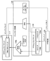
次に、図4を参照して、図3で説明した送信機13aおよび13b(図4では、総称して「送信機13」)の構成の例を説明する。図4に示すように、送信機13は、映像信号受信部131、IPパケット生成部132、PTP制御部133、PTPタイムスタンプカウンタ134、タイムスタンプ変換部135、RTPタイムスタンプカウンタ136、送信部137、およびデータネットワークインタフェース部138、および制御ネットワークインタフェース部139を備える。
Next, an example of the configuration of the
映像信号受信部131は、分配器11によって分配された映像信号を受信する。IPパケット生成部132は、映像信号をIP伝送するために、受信した映像信号からRTP/UDP/IPプロトコルで規定されたIPパケットを生成する。具体的には、RTPヘッダ、UDPヘッダ、IPヘッダ、およびMACヘッダなどを付加して、IPパケットを生成する。
The video
PTP制御部133は、制御ネットワークインタフェース部139を介してPTPグランドマスタ12からPTPのメッセージを受信し、PTPグランドマスタ12との間で時刻同期を行う。その時刻同期に基づいて、PTPタイムスタンプカウンタ134がカウントアップされる。
The
タイムスタンプ変換部135は、PTPタイムスタンプカウンタ134によってカウントアップされたタイムスタンプを、RTPタイムスタンプに変換する。SMPTE2022−2では90KHz、SMPTE2022−6では27MHzのクロックレートを使用して、32ビットのRTPタイムスタンプを設定するよう規定している。一方、PTPタイムスタンプカウンタ134は、ナノ秒カウンタを有するので、PTPのタイムスタンプとRTPのタイムスタンプとはクロックレートが大きく異なる。このPTPタイムスタンプを90KHzまたは27MHzのクロックレートによるRTPタイムスタンプに変換することによって、RTPで規定されたタイムスタンプフィールド(32ビット)を使用することができる。つまり、PTPによる誤差精度を有しつつ、従来通りのRTPで規定されたフォーマットでIPパケットを送信することができる。
The time
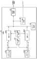
タイムスタンプの変換の具体例を図5に示す。タイムスタンプ変換部135は、PTPタイムスタンプカウンタ134のナノ秒カウンタ134aが0になったときに、秒カウンタ134bのカウンタ値と27,000,000(10進数表示)または90,000(10進数表示)とを乗算器135aで乗算した値をRTPタイムスタンプカウンタ136に設定する。SMPTE2022−6の場合には27,000,000を乗算対象として使用し、SMPTE2022−2の場合は、90,000を乗算対象として使用する。なお、説明の都合上、乗算する値は10進数で説明しているが、実際の回路においては2進数演算となることは言うまでもない。
A specific example of time stamp conversion is shown in FIG. When the
タイムスタンプ変換部135は、PTPタイムスタンプカウンタ134を更新するクロックに同期したクロックを、PTP制御部133からリファレンスクロックとして受信する。そして、そのレファレンスクロックに基づいて、PLLまたはDLLを使用して90KHzまたは27MHzのクロックを作成する。そして、作成した90KHzまたは27MHzのクロックでRTPタイムスタンプカウンタ136をカウントアップする。このようにすることによって、PTPの誤差精度を実現しつつ、RTPで規定されたタイムスタンプを生成することができる。
The time
カウントアップされたRTPタイムスタンプカウンタ136の値は、IPパケット生成部132が生成するIPパケットのRTPヘッダのRTPタイムスタンプフィールドに設定される。なお、上述した形態に限定されず、例えば、伝送する映像信号がSMPTE2022−6に従った映像信号の場合、RTPタイムスタンプカウンタ136の値をメディアペイロードヘッダにおけるビデオタイムスタンプフィールドに設定してもよい。RTPフォーマットでは、RTPヘッダの中にメディアペイロードヘッダを有し、その中にビデオタイムスタンプが規定されている。また、上述したようなPTPタイムスタンプを、RTPタイムスタンプに変換せず、RTPヘッダまたはRTPペイロードの未使用フィールドに設定してもよい。この場合、以下で説明するタイムスタンプ判定部143は、PTPタイムスタンプの値を使用して2つのIPパケットストリーム内で同一のペイロードを有するIPパケットを判定することになる。
The value of the counted-up RTP
送信部137は、IPパケット生成部132により生成されたIPパケットストリームを、データネットワークインタフェース部138を介してIPネットワーク15にパケット単位で送信する。
The
データネットワークインタフェース部138は、IPストリーム送信用のイーサネットネットワークへのインタフェース機能を有する。制御ネットワークインタフェース部139は、PTP用のイーサネットネットワークへのインタフェース機能を有する。データネットワークインタフェース部138と制御ネットワークインタフェース部139とを1つのインタフェースとして構成してもよいが、この場合には1つのネットワークインタフェースが、データネットワークインタフェース部138および制御ネットワークインタフェース部139の両機能を兼ねることになる。
The data
次に、図6を参照して、図3で説明した受信機14の構成の例を説明する。受信機14は、ネットワークインタフェース部141aおよび141b、IPパケット選択部142、タイムスタンプ判定部143、遅延バッファ144aおよび144b、シーケンス番号設定部145、ならびに映像信号生成部146を備える。
Next, an example of the configuration of the
ネットワークインタフェース部141aおよびネットワークインタフェース部141bは、伝送経路16を介して送信されるIPパケットストリームAおよび伝送経路17を介して送信されるIPパケットストリームBをそれぞれ受信する。
The
遅延バッファ144a、遅延バッファ144b(以下、総称して「遅延バッファ144」と呼ぶ)はまず、それぞれネットワークインタフェース部141aより受信したIPパケットストリームAおよびネットワークインタフェース部141bより受信したIPパケットストリームBを格納する。そして、IPパケット選択部142が映像信号生成部146に送信するIPパケットを選択する時点で両方のIPパケットストリームにおける同一のペイロードを有するIPパケットが同一のタイミングで出力されるように遅延時間を調整する。遅延バッファ144の具体的な構成の一例を図7に示す。
The
遅延バッファ144は、パケットメモリ1441、先頭空きアドレスレジスタ1442、読み出しアドレスレジスタ1443、書き込みアドレスレジスタ1444、タイムスタンプメモリ1445、ベースシーケンス番号レジスタ1446、およびシーケンス番号比較演算部1447を備える。
The
パケットメモリ1441は、遅延バッファ144が受信したIPパケットを格納する。パケットメモリ1441は再構築する映像信号に同期し、継続的に読み出される。
The
先頭空きアドレスレジスタ1442は、パケットメモリ1441における空きエリアの先頭を示す。先頭空きアドレスレジスタは、新しいIPパケットがパケットメモリ1441に書き込まれ、空きエリアが変更された時に新しい先頭空きアドレスを示すように更新される。
The start
読み出しアドレスレジスタ1443は、IPパケット選択部142に出力するIPパケットの読み出しアドレスを指示する。遅延バッファ144は、読み出しアドレスレジスタ1443により先頭位置が示され、先頭空きアドレスレジスタ1442により最終位置を示すFIFO(First In First Out)として動作する。
The read
書き込みアドレスレジスタ1444は、遅延バッファ144が受信したIPパケットを書き込むアドレスを指示する。
The
タイムスタンプメモリ1445は、パケットメモリ1441に書き込んだIPパケットのRTPタイムスタンプ値とそのIPパケットを格納したパケットメモリのアドレスの対応を示す。ベースシーケンス番号レジスタ1446は、パケットメモリ1441において読み出しアドレスレジスタ1443が指示するアドレスに格納されているIPパケットのRTPシーケンス番号を示す。シーケンス番号比較演算部1447は、ベースシーケンス番号レジスタ1446と受信したIPパケットのRTPシーケンス番号の差分を計算し読み出しアドレスレジスタ1443に加算することにより受信したIPパケットの書き込みアドレスを決定する。
The
なお、本実施形態では、説明の簡素化のために読み出しアドレス、書き込みアドレス、先頭空きアドレスは1つのIPパケットを1アドレスとするものとする。すなわち、パケットメモリの1ワードの大きさが1つのIPパケットのバイト数となる。実際の実装においては、上記のアドレスの下位にオフセットを与えて、例えば32ビットあるいは64ビットのワード幅でパケットメモリを構成することが可能である。 In the present embodiment, for the sake of simplification of the description, one IP packet is set as one address for the read address, the write address, and the first free address. That is, the size of one word in the packet memory is the number of bytes in one IP packet. In an actual implementation, it is possible to give an offset to the lower part of the above address to configure the packet memory with a word width of, for example, 32 bits or 64 bits.
読み出しアドレスレジスタ1443は、パケットメモリ1441よりIPパケットを読み出した時に、次に読み出すIPパケットを示すように更新され、読み出したIPパケットが格納されていたパケットメモリ1441におけるエリアは「空き」とされる。「空き」にする方法の一例として、例えば全て0にクリアされる。同時に、更新された読み出しアドレスレジスタ1443の示すアドレスに格納されているIPパケットのRTPシーケンス番号の値でベースシーケンス番号レジスタ1446が更新される。
When the IP packet is read from the
以下、遅延バッファ144aにIPパケットが入力された場合の動作を、タイムスタンプ判定部143の動作を含めて説明する。
Hereinafter, the operation when the IP packet is input to the
図6の説明に戻ると、タイムスタンプ判定部143はネットワークインタフェース部141aからIPパケットを受信すると、そのIPパケットのRTPタイムスタンプ値と遅延バッファ144bにおけるタイムスタンプメモリ1445における全てのエントリのタイムスタンプ値の差を取得する。そして、差が所定の範囲内にあるタイムスタンプ値が検出されなかった場合、同一のペイロードを有するIPパケットがネットワークインタフェース部141bによって受信されていないと判定する。この場合には、遅延バッファ144aのシーケンス番号比較演算部1447により当該受信IPパケットのRTPシーケンス番号がベースシーケンス番号レジスタ1446の内容と比較され、読み出しアドレスレジスタ1443の値と加算される。加算した結果の値が書き込みアドレスレジスタ1444に書き込まれ、受信したIPパケットがパケットメモリの対応するアドレスに書き込まれる。書き込みアドレスレジスタ1444に書き込まれたアドレスが、読み出しアドレスレジスタ1443の示すアドレスと、先頭空きアドレスレジスタ1442の示すアドレスの一つ前のアドレスとの間に含まれていない場合、すなわち空きエリアにある場合には、先頭空きアドレスレジスタ1442の値を、書き込まれたアドレスの次のアドレスに設定する。同時に、遅延バッファ144aにおけるタイムスタンプメモリ1445に、パケットメモリ1441に書き込んだアドレスと受信したIPパケットのタイムスタンプ値との組み合わせを登録する。
Returning to the description of FIG. 6, when the time
遅延バッファ144aのタイムスタンプメモリ1445に登録した情報は、ネットワークインタフェース部141bよりIPパケットを受信した場合に、タイムスタンプ判定部143により読み出され、IPパケットストリームAとIPパケットストリームBにおいて同一のペイロードを有するIPパケットを検出するのに使用される。
The information registered in the
タイムスタンプ判定部143は、IPパケットのRTPタイムスタンプ値と遅延バッファ144bにおけるタイムスタンプメモリ1445における全てのエントリのタイムスタンプ値との差を取得する。その結果、差が所定の範囲内にあるタイムスタンプ値が検出された場合、同一のペイロードを有するIPパケットがネットワークインタフェース部141bによってすでに受信されていると判定する。そして、受信したIPパケットを遅延バッファ144aにおいて、遅延バッファ144bと「同一の位置」に格納する。同時に遅延バッファ144aにおけるタイムスタンプメモリ1445に、パケットメモリ1441に書き込んだアドレスと受信したIPパケットのタイムスタンプ値との組み合わせを登録する。ここで「同一の位置」とは、遅延バッファ144aに格納する当該IPパケットが遅延バッファ144aより出力されるまでの遅延時間が、同一のペイロードを有するIPパケットの遅延バッファ144bでの出力までの遅延時間と等しくなる遅延バッファ144aにおける位置である。
The time
具体的には次の手順で導きだされる。
(1)遅延バッファ144bのタイムスタンプメモリ1445における同一のペイロードを有するIPパケットのタイムスタンプ値に対応するアドレス値を読み出す。
(2)(1)で読み出したアドレス値から遅延バッファ144bの読み出しアドレスレジスタ1443の値を減算する。
(3)(2)で減算した値に、遅延バッファ144aの読み出しアドレスレジスタ1443の値を加算した値を、遅延バッファ144aの書き込みアドレスとし、遅延バッファ144aの書き込みアドレスレジスタ1444に設定する。
Specifically, it is derived by the following procedure.
(1) The address value corresponding to the time stamp value of the IP packet having the same payload in the
(2) The value of the read
(3) The value obtained by adding the value of the read
上記の動作で書き込みアドレスレジスタ1444に書き込まれたアドレスが、読み出しアドレスレジスタ1443の示すアドレスと、先頭空きアドレスレジスタ1442の示すアドレスの一つ前のアドレスとの間に含まれていない場合、すなわち空きエリアにある場合には、先頭空きアドレスレジスタ1442の値を書き込んだアドレスの次のアドレスに設定する。
When the address written to the
このように二つの遅延バッファにおいて「同一の位置」に同一のペイロードを有するIPパケットを格納することにより、二つの遅延バッファの出力において現用系と予備系の両系の遅延が同一となるように調整する。 By storing IP packets having the same payload at the "same position" in the two delay buffers in this way, the delays of both the active system and the backup system are the same in the output of the two delay buffers. adjust.
IPパケットが伝送経路16あるいは17において消失した場合には、そのIPパケットが格納されるはずのパケットメモリ1441のアドレスにはIPパケットが書き込まれず、「空き」のままとなる。パケットメモリ1441の読み出しアドレスと先頭空きアドレスとの間には書き込まれたIPパケットストリームの中に「空き」のエリアが存在することとなる。
When the IP packet is lost in the
上記動作はネットワークインタフェース部141aよりIPパケットを受信した場合について記述したが、ネットワークインタフェース部141bよりIPパケットを受信した場合には、遅延バッファ144bが、上記遅延バッファ144aについて説明したのと同様の動作をする。
The above operation describes the case where the IP packet is received from the
遅延バッファ144aおよび遅延バッファ144bにおけるタイムスタンプメモリ1445に登録されたアドレスとタイムスタンプ値との組み合わせは、対象となるIPパケットがパケットメモリ1441より読み出された時に削除される。
The combination of the address registered in the
上記述べたように、タイムスタンプ判定部143は、ネットワークインタフェース部141aにより受信したIPパケットのRTPタイムスタンプ値を、ネットワークインタフェース部141bにより受信したIPパケットのRTPタイムスタンプ値と比較する。そして、比較した結果が所定の範囲内にある場合、両パケットが同一のペイロードを有するIPパケットであると判定する。具体的には、両方のIPパケットのタイムスタンプ値の差が、PTPに従って時刻同期している複数の送信機間で許容される時刻差に基づく閾値内にある場合に、同一のペイロードを有していると識別する。
As described above, the time
閾値は、例えば、分配器11によって分配された入力映像信号を送信機13aおよび13bのそれぞれが受信するタイミング誤差の統計的な最大値を考慮した値であってもよい。代わりに、受信機14が同一のペイロードを有すると判定した2つのIPパケットが生成された時刻の統計的なタイミング誤差の最大値を考慮した値であってもよい。閾値は、予め設定された固定値であってもよい。この場合、試験的に得られた統計値から閾値が設定される。また、送信機13aおよび13bのそれぞれが分配器11から映像信号を受信した時刻/各IPパケットを生成した時刻を受信機14に送信することによって、閾値が動的に更新されてもよい(この時刻は、PTPグランドマスタ12との時刻同期を行うことで得られる時刻であってもよい)。
The threshold value may be, for example, a value in consideration of the statistical maximum value of the timing error received by each of the
上記をまとめると、タイムスタンプ判定部143は、IPパケットストリームAにおけるIPパケットとIPパケットストリームBにおけるIPパケットとが同一のペイロードを有していると識別すると、各々をそれぞれ遅延バッファ144aと遅延バッファ144bの同一の位置に格納する。ここで同一の位置とは、遅延バッファの出力までの遅延が等しくなる遅延バッファにおける位置である。これにより現用系、予備系、両系の遅延が同一となるように調整する。
Summarizing the above, when the time
IPパケット選択部142は、遅延バッファ144aおよび遅延バッファ144bから継続的に読み出されて出力されるIPパケットの中から、映像信号生成部146に送信するIPパケットを選択する。
The IP
現用系および予備系の両方が正常な場合には、遅延バッファ144aにIPパケットストリームAが格納され、遅延バッファ144bにはIPパケットストリームBが格納される。両IPパケットストリーム上で同一ペイロードを有するIPパケットはタイムスタンプ判定部143の制御により遅延バッファ144aと遅延バッファ144bの「同一の位置」に置かれる。したがって、遅延バッファ144aと遅延バッファ144bにおいて同一ストリームを有するIPパケットは同一のタイミングでそれぞれの遅延バッファより出力される。IPパケット選択部142は、現用系のIPパケット、すなわち遅延バッファ144aの出力を映像信号生成部146に送信する。
When both the active system and the standby system are normal, the IP packet stream A is stored in the
現用系に障害が発生した場合、IPパケットストリームAが受信されず、遅延バッファ144aにはIPパケットが格納されず、そのIPパケット用のエリアは「空き」となる。したがって、障害発生した時のIPパケットに関しては、遅延バッファ144aからはIPパケットが出力されず、遅延バッファ144bからのみIPパケットが出力される。IPパケット選択部142は遅延バッファ144aからのIPパケットが出力されないことを検出したら即時に、遅延バッファ144bからのIPパケットを選択し映像信号生成部146に送信するように切替える。
When a failure occurs in the active system, the IP packet stream A is not received, the IP packet is not stored in the
なお、タイムスタンプ判定部143は、上述した判定処理において、IPパケットのRTPヘッダにおけるマーカービット(Mビット)(入力映像信号がSMPTE2022−6に準拠している場合)、またはTSヘッダにおけるペイロードユニット開始インジケータ(入力映像信号がSMPTE2022−2に準拠している場合)の値を参照してもよい。ここで、Mビットまたはペイロードユニット開始インジケータは、映像フレームの境界を示す値が設定される。すなわち、IPパケットのMビット(またはペイロードユニット開始インジケータ)に映像境界を示す値が設定されている場合、IPパケットが映像フレーム境界を示すパケット(以下、映像フレーム境界IPパケットと呼ぶ)であることを意味する。
In the determination process described above, the time
両系のIPパケットストリームのIPパケットが同一のタイミングで映像フレーム境界パケットである場合、両方のIPパケットが同一のペイロードを有している可能性が高いと判断することができる。つまり、RTPタイムスタンプが所定の閾値内にあると判定することに加え、両方のIPパケットが同一のタイミングで映像フレーム境界にあると判定することによって、両方のIPパケットが同一のペイロードを有していると判定することの精度がさらに高まることになる。 When the IP packets of the IP packet streams of both systems are video frame boundary packets at the same timing, it can be determined that there is a high possibility that both IP packets have the same payload. That is, in addition to determining that the RTP time stamp is within a predetermined threshold, both IP packets have the same payload by determining that both IP packets are at the video frame boundary at the same timing. The accuracy of determining that the packet is correct will be further improved.
映像信号生成部146は、IPパケット選択部142から送られたIPパケットに基づいて、映像信号を再構築する。再構築された映像信号は、中継局などの受信機に伝送される。
The video
シーケンス番号設定部145は、IPパケット選択部142から送信されたIPパケットのMACヘッダ、IPヘッダ、UTPヘッダの一部または全部を変更し、連番でRTPシーケンス番号を設定する。そして、シーケンス番号が設定されたIPパケットから新しいIPパケットストリームを作成し、受信機14より出力する。上述したように、送信機13aおよび13bがそれぞれのIPパケットに設定するRTPシーケンス番号には、同一の値が設定されるとは限らない。これを、正確な順序付けに対応したRTPシーケンス番号を新たに設定することによって、受信機が後続の中継装置に伝送する場合など(受信機が中継機として機能する場合)、後続の機器が上述したタイムスタンプによる判定処理を行わずに、RTPシーケンス番号のみに基づいて映像信号を再構築することができる。
The sequence
以上説明したように、受信機は、複数の伝送経路で送信された複数のIPパケットに対し、タイムスタンプに基づいて同一ペイロードを有するかの判定を行っているので、冗長化された送信機間でRTPシーケンス番号を合わせる必要がない。つまり、冗長化された複数の送信機のそれぞれは、PTPによって時刻同期されたタイムスタンプを設定してIPパケットを送信することのみでよい。そして、そのタイムスタンプ値が、PTPに従って設定されるので、高精度の判定が可能になる。 As described above, since the receiver determines whether or not the plurality of IP packets transmitted by the plurality of transmission paths have the same payload based on the time stamp, the redundant transmitters are used. There is no need to match the RTP sequence number with. That is, each of the plurality of redundant transmitters only needs to set a time stamp time-synchronized by PTP and transmit the IP packet. Then, since the time stamp value is set according to PTP, highly accurate determination becomes possible.
また、送信機はPTPタイムスタンプをRTPタイムスタンプに変換しているので、従来通りのRTPに従ったフォーマットでIPパケットを送信することができる。さらに、受信機において正確な順序付けに対応したRTPシーケンス番号を設定しているので、本実施形態に係る映像切替システム以外の中継機、受信機でも、本実施形態の受信機からのIPパケットストリームを受信し、RTPに従った従来通りの方式で中継あるいは映像信号の再構成が可能になる。 Further, since the transmitter converts the PTP time stamp into the RTP time stamp, the IP packet can be transmitted in the format according to the conventional RTP. Further, since the RTP sequence number corresponding to the accurate ordering is set in the receiver, the IP packet stream from the receiver of the present embodiment can be transmitted to the repeater and the receiver other than the video switching system according to the present embodiment. Upon reception, the relay or video signal can be reconstructed in the conventional manner according to RTP.
次に、図8を参照して、IPパケットの一部が消失(ロスト)した場合の例を説明する。 Next, an example in which a part of the IP packet is lost (lost) will be described with reference to FIG.
図8に示すように、送信機13aが送信する現用系のIPパケットストリームAの各IPパケットは、「1」乃至「4」のRTPシーケンス番号が設定される。一方、送信機13bが送信する予備系のIPパケットストリームBの各IPパケットは、「5」乃至「8」のRTPシーケンス番号が設定され、それぞれが、「1」乃至「4」のRTPシーケンス番号が設定された4つのIPパケットと同一のペイロードを有する。上述したように、送信機13aと13bとの間で、シーケンス番号を合わせないので、同一のペイロードを有するIPパケットであっても、必ずしも同一のシーケンス番号が設定されない。図8の例では、IPパケットストリームAの4つのIPパケットのうちRTPシーケンス番号に「3」が設定されたIPパケット(切替対象IPパケット)が何らかの理由で、IPネットワーク15上で消失したものとする。
As shown in FIG. 8, each IP packet of the active system IP packet stream A transmitted by the
まず、受信機14のIPパケット選択部142は、伝送経路16を介して受信されたIPパケットストリームAの2つのIPパケットを選択し、映像信号生成部146へ送信する。次のIPパケットの選択時に、RTPシーケンス番号「3」のIPパケットが存在しないと判定され、遅延バッファ144bの出力のRTPシーケンス番号「7」のIPパケットに切り替えられる。その後、IPパケット選択部142は遅延バッファ144aの出力であるRTPシーケンス番号4のIPパケットと、遅延バッファ144bの出力であるRTPシーケンス番号「8」のIPパケットとを検出し、現用系のRTPシーケンス番号「4」のIPパケットを選択し映像信号生成部146へ送信する。
First, the IP
図8に示す例では、予備系のIPパケットを選択するように切り替えた後、現用系のRTPシーケンス番号「4」のIPパケットを検出しても、予備系のIPパケットを選択し続ける実施形態も考えられる。 In the example shown in FIG. 8, after switching to select the spare system IP packet, even if the IP packet of the active system RTP sequence number “4” is detected, the backup system IP packet is continuously selected. Is also possible.
図8の例でも、冗長化された複数の送信機が相互にRTPシーケンス番号を合わせる必要なく、消失したIPパケットと同一のペイロードを有する予備系のIPパケットを判定することができる。このようにして、現用系に障害が発生しなくとも、IPパケットの一部が消失した場合に対処することができる。 Also in the example of FIG. 8, it is possible for a plurality of redundant transmitters to determine a backup IP packet having the same payload as the lost IP packet without having to match the RTP sequence numbers with each other. In this way, even if a failure does not occur in the active system, it is possible to deal with the case where a part of the IP packet is lost.
<第2の実施形態>
次に、本発明の第2の実施形態を説明する。第2の実施形態では、入力映像信号がSMPTE2022−6に準拠している場合にはMビット(または、入力映像信号がSMPTE2022−2に準拠している場合、TSヘッダにおけるペイロードユニット開始インジケータ)およびRTPシーケンス番号に基づいて、同一のペイロードを有するIPパケットを判定することによって伝送経路の切り替えを行う。
<Second embodiment>
Next, a second embodiment of the present invention will be described. In the second embodiment, the M bits (or the payload unit start indicator in the TS header if the input video signal conforms to SMPTE2022-2) and if the input video signal conforms to SMPTE2022-6. The transmission path is switched by determining IP packets having the same payload based on the RTP sequence number.
図9に第2の実施形態の構成を示す。本実施形態に係る映像切替システムは、分配器11、送信機13a、送信機13b、受信機94を備える。送信機13aおよび送信機13b、受信機94は、IPネットワーク95を介して相互に接続される。送信機13aと受信機94との間には伝送経路96が存在し、送信機13bと受信機94との間には伝送経路97が存在する。ここで、伝送経路96の遅延時間は伝送経路97より大きいものとする。
FIG. 9 shows the configuration of the second embodiment. The video switching system according to the present embodiment includes a
図9に示す第2の実施形態に係る映像切替システムは、PTPを使用しないことおよび受信機94の構成以外については、第1の実施形態に係る構成要素と同一である。
The video switching system according to the second embodiment shown in FIG. 9 is the same as the components according to the first embodiment except that PTP is not used and the configuration of the
図10に第2の実施形態に係る受信機94の構成を示す。受信機94は第1の実施形態に係る受信機14が備えるタイムスタンプ判定部を含まず、フレーム境界判定部948およびシーケンス番号判定部949を含む。また、第2の実施形態の遅延バッファ944aおよび944bは、第1の実施形態に係る受信機14の遅延バッファ144aおよび144bが供えるタイムスタンプメモリを必要とせず、図11に示す単純なFIFOの構造となる。その他の構成要素については、第1の実施形態の受信機14に係る構成要素と同一である。
FIG. 10 shows the configuration of the
フレーム境界判定部948は、ネットワークインタフェース部141aおよびネットワークインタフェース部141bを介して受信した2つのIPパケットストリームにおけるIPパケットが映像フレームの境界のIPパケット(映像フレーム境界IPパケット)であるかを判定する。具体的には、受信したIPパケットがSMPTE2022−6に準拠している場合には、RTPヘッダのマーカービットの値を参照し、該当のIPパケットが映像フレーム境界IPパケットであるか否かを判定する。該当のIPパケットが映像フレーム境界IPパケットである場合、映像フレーム境界IPパケットを格納した遅延バッファのRTPシーケンス番号がシーケンス番号判定部949に渡される。なお、受信したIPパケットがSMPTE2022−2に準拠している場合、TSヘッダにおけるペイロードユニット開始インジケータの値が参照されて、映像フレーム境界IPパケットであるかを判定する。
The frame
IPパケットストリームAおよびBはそれぞれ、独立してRTPシーケンス番号が設定されている。シーケンス番号判定部949は、フレーム境界判定部948によって判定された両系の映像フレーム境界IPパケットのRTPシーケンス番号を渡される。IPパケットストリームAが伝送される伝送経路96の遅延時間はIPパケットストリームBが伝送される伝送経路97より大きい。したがって、同一のペイロードを有する映像フレーム境界IPパケットに関しては、IPパケットストリームBにおけるIPパケットがより早く受信機14によって受信され、シーケンス番号判定部949にRTPシーケンス番号が渡される。その後IPパケットストリームAにおけるIPパケットが受信機14によって受信され、シーケンス番号判定部949にRTPシーケンス番号が渡される。
RTP sequence numbers are set independently for each of the IP packet streams A and B. The sequence
遅延バッファ944bにネットワークインタフェース部141aから受信IPパケットが渡されると、図11のシーケンス番号比較演算部1447により当該受信IPパケットのRTPシーケンス番号がベースシーケンス番号レジスタ1446の内容と比較され、読み出しアドレスレジスタ1443の値と加算される。加算した結果の値が書き込みアドレスレジスタ1444に書き込まれ、受信したIPパケットがパケットメモリの対応するアドレスに書き込まれる。書き込みアドレスレジスタ1444に書き込まれたアドレスが、読み出しアドレスレジスタ1443の示すアドレスと、先頭空きアドレスレジスタ1442の示すアドレスの一つ前のアドレスとの間に含まれていない場合、すなわち空きエリアにある場合には、先頭空きアドレスレジスタ1442の値を書き込んだアドレスの次のアドレスに設定する。
When the received IP packet is passed from the
シーケンス番号判定部949は、フレーム境界判定部948から受信したIPパケットストリームBにおける映像フレーム境界IPパケットのRTPシーケンス番号(基準番号B)を記憶する。同時に、遅延バッファ944bにおける書き込みアドレスレジスタ1444の値を読み、当該映像フレーム境界IPパケットを格納したアドレス(フレーム境界アドレスb)を記憶する。
The sequence
その後、シーケンス番号判定部949はフレーム境界判定部948からIPパケットストリームAにおける映像フレーム境界IPパケットのRTPシーケンス番号(基準番号A)を受信すると、IPパケットストリームBにおけるフレーム境界IPパケットの遅延バッファ144bにおける「同一の位置」で遅延バッファ944aに格納する。ここで「同一の位置」とは、遅延バッファ144aに格納する映像フレーム境界IPパケットが遅延バッファ144aより出力されるまでの遅延時間が、遅延バッファ144bで映像フレーム境界IPパケットの出力までの遅延時間と等しくなる遅延バッファ144aにおける位置である。具体的には次の手順で導きだされる。
(1)遅延バッファ944bのフレーム境界アドレスbから遅延バッファ944bの読み出しアドレスレジスタ1443の値を減算する。
(2)(1)の値を遅延バッファ944aの読み出しアドレスレジスタの値に加算した値を書き込みアドレス(フレーム境界アドレスa)とする。
After that, when the sequence
(1) The value of the read
(2) The value obtained by adding the value of (1) to the value of the read address register of the
上記の動作で書き込みアドレスレジスタ1444に書き込まれたアドレスが、読み出しアドレスレジスタ1443の示すアドレスと、先頭空きアドレスレジスタ1442の示すアドレスの一つ前のアドレスとの間に含まれていない場合、すなわち空きエリアにある場合には、先頭空きアドレスレジスタ1442の値を書き込んだアドレスの次のアドレスに設定する。
When the address written to the
遅延バッファ944aおよび944bに映像フレーム境界IPパケットを書き込んだ後、IPパケットストリームAにおけるIPパケットを受信した場合、シーケンス番号判定部949はRTPシーケンス番号から基準番号Aを減算する。そして、その差分に対応する値をフレーム境界アドレスaに加算した値を書き込みアドレスレジスタ1444に書き込み、当該IPパケットを遅延バッファ944aに書き込む。この時に書き込みアドレスレジスタ1444に書き込まれたアドレスが、読み出しアドレスレジスタ1443の示すアドレスと、先頭空きアドレスレジスタ1442の示すアドレスの一つ前のアドレスのと間に含まれていない場合、すなわち空きエリアにある場合には、遅延バッファ944aにおける先頭空きアドレスレジスタ1442の値を書き込んだアドレスの次のアドレスに設定する。
When the IP packet in the IP packet stream A is received after writing the video frame boundary IP packet to the
同様にIPパケットストリームBにおけるIPパケットを受信した場合、シーケンス番号判定部949はRTPシーケンス番号から基準番号Bを減算する。そして、その差分に対応する値をフレーム境界アドレスbに加算した値を書き込みアドレスレジスタ1444に書き込み、当該IPパケットを遅延バッファ944bに書き込む。この時に書き込みアドレスレジスタ1444に書き込まれたアドレスが、読み出しアドレスレジスタ1443の示すアドレスと、先頭空きアドレスレジスタ1442の示すアドレスの一つ前のアドレスとの間に含まれていない場合、すなわち空きエリアにある場合には、遅延バッファ944bにおける先頭空きアドレスレジスタ1442の値を書き込んだアドレスの次のアドレスに設定する。
Similarly, when the IP packet in the IP packet stream B is received, the sequence
上記をまとめると、シーケンス番号判定部949は、IPパケットストリームAにおける映像フレーム境界IPパケットとIPパケットストリームBにおける映像フレーム境界IPパケットとを識別し、各々をそれぞれ遅延バッファ944aと遅延バッファ944bとの「同一の位置」に格納する。ここで「同一の位置」とは、遅延バッファの出力までの遅延が等しくなる遅延バッファにおける位置である。これにより現用系と予備系の両系の遅延が同一となるように調整する。
Summarizing the above, the sequence
表1は、RTPシーケンス番号の具体的な値を一例として示す。 Table 1 shows specific values of RTP sequence numbers as an example.

表1に示すように、IPパケットストリームAにおいてRTPシーケンス番号1029のIPパケットが映像フレーム境界IPパケットの場合、基準番号Aは1029である。IPパケットストリームBにおいてRTPシーケンス番号3016のIPパケットが映像フレーム境界IPパケットの場合、基準番号Bは3016である。 As shown in Table 1, when the IP packet of RTP sequence number 1029 is a video frame boundary IP packet in the IP packet stream A, the reference number A is 1029. In the IP packet stream B, when the IP packet of RTP sequence number 3016 is a video frame boundary IP packet, the reference number B is 3016.
IPパケット選択部142は、遅延バッファ944aおよび遅延バッファ944bから継続的に読み出されて出力されるIPパケットの中から、映像信号生成部147に送信するIPパケットを選択する。
The IP
現用系、予備系とも正常な場合には、遅延バッファ944aにIPパケットストリームAが格納され、遅延バッファ944bにはIPパケットストリームBが格納される。両IPパケットストリーム上で同一ペイロードを有するIPパケットはシーケンス番号判定部949の制御により遅延バッファ944aと遅延バッファ944bの「同一の位置」に置かれる。したがって、遅延バッファ944aと遅延バッファ944bにおいて同一ペイロードを有する二つのIPパケットは同一のタイミングでそれぞれの遅延バッファより出力される。IPパケット選択部142は、現用系のIPパケット、すなわち遅延バッファ944aの出力を映像信号生成部147に送信する。
When both the active system and the standby system are normal, the IP packet stream A is stored in the
現用系に障害が発生した場合、IPパケットストリームAが受信されず、遅延バッファ944aにはIPパケットが格納されず、そのIPパケット用のエリアは「空き」となる。したがって、障害発生した時のIPパケットに関しては、遅延バッファ944aからはIPパケットが出力されず、遅延バッファ944bからのみIPパケットが出力される。IPパケット選択部142は遅延バッファ944aからIPパケットが出力されないことを検出したら即時に、遅延バッファ944bからのIPパケットを選択し、映像信号生成部147に送信するように切替える。表1の例では、受信するIPパケットストリームAにRTPシーケンス番号1033のIPパケットが含まれない。したがって、遅延バッファ944aの出力にRTPシーケンス番号1032のIPパケットに連続するIPパケットが無いことをIPパケット選択部142が検出し、IPパケット選択部142が映像信号生成部147に送信するIPパケットのソースを遅延バッファ944aから遅延バッファ944bへ切替え、RTPシーケンス番号3020のIPパケットを映像信号生成部147に送信する。
When a failure occurs in the active system, the IP packet stream A is not received, the IP packet is not stored in the
映像信号生成部147は、IPパケット選択部142から送信されたIPパケットに基づいて、映像信号を再構築する。再構築された映像信号は、中継局などの受信機に伝送される。
The video
シーケンス番号設定部145は、IPパケット選択部142から送信されたIPパケットのMACヘッダ、IPヘッダ、UTPヘッダの一部または全部を変更し、連番でRTPシーケンス番号を設定し、新しいIPパケットストリームを作成し、受信機94より出力する。上述したように、送信機13aおよび13bがそれぞれのIPパケットに設定するRTPシーケンス番号には、同一の値が設定されるとは限らない。これを、正確な順序付けに対応したRTPシーケンス番号を新たに設定することによって、受信機が後続の中継装置に伝送する場合など(受信機が中継機として機能する場合)、後続の機器が上述したタイムスタンプによる判定処理を行わずに、RTPシーケンス番号のみに基づいて映像信号を再構築することができる。
The sequence
以上説明したように、受信機は、複数の伝送経路で送信された複数のIPパケットに対し、映像フレーム境界IPパケットとRTPシーケンス番号に基づいて同一ペイロードを有するかの判定を行っているので、冗長化された送信機間でRTPシーケンス番号を合わせる必要がない。 As described above, since the receiver determines whether or not the plurality of IP packets transmitted by the plurality of transmission paths have the same payload based on the video frame boundary IP packet and the RTP sequence number. There is no need to match RTP sequence numbers between redundant transmitters.
本実施形態の説明においては、伝送経路96の遅延時間は伝送経路97より大きいこととその遅延時間の差が1映像フレーム時間以内であることを前提としている。もし、伝送経路97の遅延時間が伝送経路96より大きい場合、前述した受信機94における処理はIPパケットストリームAとIPパケットストリームBを入れ替えたものとなる。また、遅延時間の差が1映像フレームより大きい場合には図12に示す様に遅延バッファ944bの前段に遅延バッファ944a、944bの入り口での遅延時間を1映像フレーム以内にするための別の遅延バッファ947を設ける必要がある。
In the description of the present embodiment, it is assumed that the delay time of the
図12では遅延時間が4映像フレームから5映像フレームでの構成を示しており、4映像フレームの固定遅延を与える遅延バッファ947を設けている。遅延バッファ947は遅延バッファ944a、944bと同一の構成だが、先頭空きアドレスと読み出しアドレスの差を常に4映像フレーム分、すなわち
4×IPパケット数/映像フレーム
空けるように制御し、IPパケットを受信した時は先頭空きアドレスレジスタの値を書き込みアドレスレジスタに移し、IPパケットを書き込み、その後、先頭空きアドレスレジスタの値を更新する。
FIG. 12 shows a configuration in which the delay time is from 4 video frames to 5 video frames, and a
なお、上記の制御を行うには、伝送経路96と97の遅延時間の差を計る必要があるが、従来の技術で容易に実現可能であり、一例をあげて、詳細な説明は省略する。この遅延時間差測定の一例としては、カラーバーなどの特定の映像信号をIPパケットストリームAおよびIPパケットストリームBで伝送し、内部遅延時間が同一の二つの受信機によりIPパケットストリームAおよびIPパケットストリームBを受信し、再構築済みの映像信号間の遅延時間を計ることである。
In order to perform the above control, it is necessary to measure the difference in delay time between the
なお、本実施形態においては、2つのIPパケットストリームにおけるIPパケットのRTPヘッダまたはRTPペイロードの未使用フィールドに、IPパケットストリームにおいて映像フレーム境界IPパケットからのIPパケット数を示すカウント値のフィールドを設けるように構成してもよい。このカウント値は、映像フレーム境界IPパケットを示す場合に初期化される。IPパケットストリームAとIPパケットストリームBのIPパケットのカウンタ値が一致する場合、両方のIPパケットが同一のペイロードを有していると判定することができる。このカウント値は、送信機13aおよび13bに実装される。この場合、同一ペイロードを有するIPパケットの判定にRTPシーケンス番号を使用する必要はない。
In the present embodiment, a count value field indicating the number of IP packets from the video frame boundary IP packet in the IP packet stream is provided in the unused field of the RTP header or RTP payload of the IP packet in the two IP packet streams. It may be configured as follows. This count value is initialized when indicating a video frame boundary IP packet. When the counter values of the IP packets of the IP packet stream A and the IP packet stream B match, it can be determined that both IP packets have the same payload. This count value is implemented in
以上説明したように、第2の実施形態では、IPパケットストリームAおよびBにおけるIPパケットが、映像フレーム境界から何番目のIPパケットであるかに基づいて両方のIPパケットを特定しているので、送信機13aおよび13bが相互にRTPシーケンス番号を合わせる必要がない。また、RTPシーケンス番号または映像フレーム境界IPパケットからのカウント値に基づいて同一のペイロードを有するか否かを判定しているので、送信機13aおよび13bがPTPスレーブを実装する必要がない。
As described above, in the second embodiment, both IP packets are specified based on the number of IP packets from the video frame boundary as the IP packets in the IP packet streams A and B. The
上述した第2の実施形態で説明した方式は、図8で説明したIPパケットの一部が消失(ロスト)した場合にも適用することができる。 The method described in the second embodiment described above can also be applied to the case where a part of the IP packet described in FIG. 8 is lost.
以上のように、本発明に係る映像切替システムを説明した。上記説明した各構成要素が実行する処理、およびその処理の順序は例示的なものであることに留意されたい。 As described above, the video switching system according to the present invention has been described. It should be noted that the processing performed by each component described above and the order of the processing are exemplary.
A IPパケットストリーム
B IPパケットストリーム
4 伝送経路
5 伝送経路
16 伝送経路
17 伝送経路
A IP packet stream B
Claims (11)
前記PTPグランドマスタとPTPに従って時刻同期する第1の送信機と、
前記PTPグランドマスタとPTPに従って時刻同期する第2の送信機と、
前記第1の送信機および前記第2の送信機とIPネットワークを介して接続された受信機とを備え、
前記第1の送信機および前記第2の送信機のそれぞれは、
1つの映像信号から分配された映像信号を入力とし、
前記入力された映像信号を複数のIPパケットに分割し、
前記PTPに従って同期した時刻に基づいたタイムスタンプを、前記分割した複数のIPパケットのそれぞれに設定し、前記第1の送信機によって分割された第1の複数のIPパケットおよび前記第2の送信機によって分割された第2の複数のIPパケットは、同一のペイロードを有し、
前記第1の送信機は、前記タイムスタンプが設定された前記第1の複数のIPパケットを第1のIPパケットストリームとして、RTPに従って、第1の伝送経路を介して送信し、
前記第2の送信機は、前記タイムスタンプが設定された前記第2の複数のIPパケットを第2のIPパケットストリームとして、RTPに従って、第2の伝送経路を介して送信する
ことを特徴とする映像切替システム。 With PTP Grand Master,
A first transmitter that synchronizes time with the PTP ground master according to PTP,
A second transmitter that synchronizes time with the PTP ground master according to PTP,
The first transmitter and the second transmitter are provided with a receiver connected via an IP network.
Each of the first transmitter and the second transmitter
The video signal distributed from one video signal is used as the input.
The input video signal is divided into a plurality of IP packets, and the input video signal is divided into a plurality of IP packets.
A time stamp based on the time synchronized according to the PTP is set for each of the divided IP packets, and the first plurality of IP packets divided by the first transmitter and the second transmitter are used. The second plurality of IP packets divided by have the same payload and
The first transmitter transmits the first plurality of IP packets set with the time stamp as the first IP packet stream, according to RTP, via the first transmission path.
The second transmitter is characterized in that the second plurality of IP packets set with the time stamp are transmitted as a second IP packet stream via the second transmission path according to RTP. Video switching system.
前記第1のIPパケットストリームおよび前記第2のIPパケットストリームにおいてそれぞれのIPパケットに設定された前記タイムスタンプを比較し、
比較結果が所定の範囲内にあることに基づいて、前記第1のIPパケットストリームおよび前記第2のIPパケットストリームにおいてそれぞれ同一のペイロードを有する2つのIPパケットを含むIPパケット対を識別し、
前記IPパケット対を受信する場合は、前記IPパケット対のうちのいずれかのIPパケットを選択して映像信号を再構築し、
前記IPパケット対のうちの1つのIPパケットのみを受信する場合は、前記1つのIPパケットを使用して映像信号を再構築する
ことを特徴とする請求項1に記載の映像切替システム。 The receiver
The time stamps set for each IP packet in the first IP packet stream and the second IP packet stream are compared.
Based on the comparison result being within a predetermined range, an IP packet pair containing two IP packets having the same payload in the first IP packet stream and the second IP packet stream is identified.
When receiving the IP packet pair, one of the IP packet pairs is selected to reconstruct the video signal.
The video switching system according to claim 1, wherein when receiving only one IP packet out of the IP packet pair, the video signal is reconstructed using the one IP packet.
前記第1の送信機および前記第2の送信機は、PTPによる時刻情報をRTPタイムスタンプに変換する
ことを特徴とする請求項1乃至3のいずれか一項に記載の映像切替システム。 The time stamp based on the time synchronized according to the PTP is an RTP time stamp.
The video switching system according to any one of claims 1 to 3, wherein the first transmitter and the second transmitter convert time information by PTP into an RTP time stamp.
前記第1のIPパケットストリームおよび前記第2のIPパケットストリームにおいてそれぞれのIPパケットに設定された前記タイムスタンプを比較し、
比較結果が所定の範囲内にあることに基づいて、前記第1のIPパケットストリームおよび前記第2のIPパケットストリームにおいてそれぞれ同一のペイロードを有する2つのIPパケットを含むIPパケット対を識別し、
前記IPパケット対を受信する場合は、前記IPパケット対のうちのいずれかのIPパケットを選択して第3のIPストリームを構築し、
前記IPパケット対のうちの1つのIPパケットのみを受信する場合は、前記1つのIPパケットを使用して前記第3のIPストリームを構築する
ことを特徴とする請求項1に記載の映像切替システム。 The receiver
The time stamps set for each IP packet in the first IP packet stream and the second IP packet stream are compared.
Based on the comparison result being within a predetermined range, an IP packet pair containing two IP packets having the same payload in the first IP packet stream and the second IP packet stream is identified.
When receiving the IP packet pair, one of the IP packet pairs is selected to construct a third IP stream.
The video switching system according to claim 1, wherein when only one IP packet out of the IP packet pair is received, the third IP stream is constructed by using the one IP packet. ..
前記IPパケットのMACヘッダ、IPヘッダ、UDPヘッダのうちの少なくとも1つを変更し、新たな連番のRTPシーケンス番号を前記第3のIPストリームに設定することを特徴とする請求項5に記載の映像切替システム。 The receiver
The fifth aspect of claim 5, wherein at least one of the MAC header, the IP header, and the UDP header of the IP packet is changed and a new serial number RTP sequence number is set in the third IP stream. Video switching system.
前記複数の送信機のうちの第1の送信機は、
PTPグランドマスタとPTPに従って時刻同期し、
前記分配された入力映像信号を第1の複数のIPパケットに分割し、
前記PTPに従って同期した時刻に基づくタイムスタンプを、前記分割した第1の複数のIPパケットのそれぞれに設定し、
前記タイムスタンプが設定された前記第1の複数のIPパケットを第1のIPパケットストリームとして、RTPに従って、第1の伝送経路を介して送信し、
前記複数の送信機のうちの第2の送信機は、
前記PTPグランドマスタとPTPに従って時刻同期し、
前記分配された入力映像信号を第2の複数のIPパケットに分割し、
前記PTPに従って同期した時刻に基づくタイムスタンプを、前記分割した第2の複数のIPパケットのそれぞれに設定し、前記第1の複数のIPパケットおよび前記第2の複数のIPパケットは、同一のペイロードを有し、
前記タイムスタンプが設定された前記第2の複数のIPパケットを第2のIPパケットストリームとして、RTPに従って、第2の伝送経路を介して送信する
ことを特徴とする映像送信機。 A plurality of transmitters that input video signals distributed from one video signal.
The first transmitter among the plurality of transmitters is
Time synchronization with PTP grand master according to PTP,
The distributed input video signal is divided into a first plurality of IP packets, and the distributed input video signal is divided into a plurality of first IP packets.
A time stamp based on the time synchronized according to the PTP is set for each of the divided first plurality of IP packets.
The first plurality of IP packets set with the time stamp are transmitted as the first IP packet stream via the first transmission path according to RTP.
The second transmitter of the plurality of transmitters is
Time synchronization with the PTP grand master according to PTP,
The distributed input video signal is divided into a second plurality of IP packets, and the distributed input video signal is divided into a plurality of second IP packets.
A time stamp based on the time synchronized according to the PTP is set for each of the divided second IP packets, and the first plurality of IP packets and the second plurality of IP packets have the same payload. Have,
A video transmitter characterized in that the second plurality of IP packets set with the time stamp are transmitted as a second IP packet stream via a second transmission path according to RTP.
入力された前記映像信号を第1の複数のIPパケットに分割し、
前記第1の複数のIPパケットを第1のIPパケットストリームとして、RTPに従って、第1の伝送経路を介して送信する第1の送信機と、
前記分配された映像信号を入力とし、
入力された前記映像信号を第2の複数のIPパケットに分割し、前記第1の複数のIPパケットおよび前記第2の複数のIPパケットは、同一のペイロードを有し、
前記第2の複数のIPパケットを第2のIPパケットストリームとして、RTPに従って、第2の伝送経路を介して送信する第2の送信機と、
前記第1の送信機および前記第2の送信機とIPネットワークを介して接続された受信機と
を備え、
前記受信機は、
前記第1のIPパケットストリームのうちの映像フレーム境界を示す第1のIPパケットを判定し、
前記第2のIPパケットストリームのうちの映像フレーム境界を示す第2のIPパケットを判定し、
前記第1のIPパケットストリームのうちのいずれかのIPパケットのシーケンス番号と、前記第1のIPパケットのシーケンス番号との第1の比較を行い、
前記第2のIPパケットストリームのうちのいずれかのIPパケットのシーケンス番号と、前記第2のIPパケットのシーケンス番号との第2の比較を行い、
前記第1の比較と前記第2の比較との結果が一致したことに基づいて、前記第1のIPパケットストリームおよび前記第2のIPパケットストリームにおいてそれぞれ同一のペイロードを有する2つのIPパケットを含むIPパケット対を識別し、
前記IPパケット対を受信する場合は前記IPパケット対のうちのいずれかのIPパケットを選択して映像信号を再構築し、
前記IPパケット対のうちの1つのIPパケットのみを受信する場合は、前記1つのIPパケットを使用して映像信号を再構築する
ことを特徴とする映像切替システム。 The video signal distributed from one video signal is used as the input.
The input video signal is divided into a first plurality of IP packets, and the video signal is divided into a plurality of first IP packets.
A first transmitter that transmits the first plurality of IP packets as a first IP packet stream through a first transmission path according to RTP.
Using the distributed video signal as an input
Dividing the input video signal to a second plurality of IP packets, the first plurality of IP packets and the second plurality of IP packets have the same payload,
A second transmitter that transmits the second plurality of IP packets as a second IP packet stream via a second transmission path according to RTP.
The first transmitter and the second transmitter are provided with a receiver connected via an IP network.
The receiver
The first IP packet indicating the video frame boundary in the first IP packet stream is determined, and the result is determined.
The second IP packet indicating the video frame boundary in the second IP packet stream is determined and determined.
A first comparison is made between the sequence number of any IP packet in the first IP packet stream and the sequence number of the first IP packet.
A second comparison is made between the sequence number of any IP packet in the second IP packet stream and the sequence number of the second IP packet.
Based on the agreement between the results of the first comparison and the second comparison, the first IP packet stream and the second IP packet stream include two IP packets having the same payload. Identify IP packet pairs and
When receiving the IP packet pair, one of the IP packet pairs is selected to reconstruct the video signal.
A video switching system characterized in that a video signal is reconstructed using the one IP packet when receiving only one IP packet out of the IP packet pair.
第1のIPパケットストリームを、RTPに従って、第1の伝送経路を介して受信し、
第2のIPパケットストリームを、RTPに従って、第2の伝送経路を介して受信し、
前記第1のIPパケットストリームのうちの映像フレーム境界を示す第1のIPパケットを判定し、
前記第2のIPパケットストリームのうちの映像フレーム境界を示す第2のIPパケットを判定し、
前記第1のIPパケットストリームのうちのいずれかのIPパケットのシーケンス番号と、前記第1のIPパケットのシーケンス番号との第1の比較を行い、
前記第2のIPパケットストリームのうちのいずれかのIPパケットのシーケンス番号と、前記第2のIPパケットのシーケンス番号との第2の比較を行い、
前記第1の比較と前記第2の比較の結果が一致したことに基づいて、前記第1のIPパケットストリームおよび前記第2のIPパケットストリームにおいてそれぞれ同一のペイロードを有する2つのIPパケットを含むIPパケット対を識別し、
前記IPパケット対を受信する場合は前記IPパケット対のうちのいずれかのIPパケットを選択して映像信号を再構築し、
前記IPパケット対のうちの1つのIPパケットのみを受信する場合は、前記1つのIPパケットを使用して映像信号を再構築する
ことを特徴とする映像受信機。 Connected to the first and second transmitters via an IP network,
The first IP packet stream is received via the first transmission path according to RTP.
The second IP packet stream is received via the second transmission path according to RTP.
The first IP packet indicating the video frame boundary in the first IP packet stream is determined, and the result is determined.
The second IP packet indicating the video frame boundary in the second IP packet stream is determined and determined.
A first comparison is made between the sequence number of any IP packet in the first IP packet stream and the sequence number of the first IP packet.
A second comparison is made between the sequence number of any IP packet in the second IP packet stream and the sequence number of the second IP packet.
Based on the agreement between the results of the first comparison and the second comparison, an IP containing two IP packets having the same payload in the first IP packet stream and the second IP packet stream, respectively. Identify packet pairs and
When receiving the IP packet pair, one of the IP packet pairs is selected to reconstruct the video signal.
A video receiver characterized in that, when receiving only one IP packet out of the IP packet pair, the video signal is reconstructed using the one IP packet.
入力された前記映像信号を第1の複数のIPパケットに分割し、
前記第1の複数のIPパケットを第1のIPパケットストリームとして、RTPに従って、第1の伝送経路を介して送信する第1の送信機と、
前記分配された映像信号を入力とし、
入力された前記映像信号を第2の複数のIPパケットに分割し、
前記第2の複数のIPパケットを第2のIPパケットストリームとして、RTPに従って、第2の伝送経路を介して送信する第2の送信機であって、前記第1の複数のIPパケットおよび前記第2の複数のIPパケットは、同一のペイロードを有する、第2の送信機と、
前記第1の送信機および前記第2の送信機とIPネットワークを介して接続された受信機と
を備え、
前記受信機は、
前記第1のIPパケットストリームのうちの映像フレーム境界を示す第1のIPパケットを判定し、
前記第2のIPパケットストリームのうちの映像フレーム境界を示す第2のIPパケットを判定し、
前記第1のIPパケットストリームのうちのいずれかのIPパケットのシーケンス番号と、前記第1のIPパケットのシーケンス番号との第1の比較を行い、
前記第2のIPパケットストリームのうちのいずれかのIPパケットのシーケンス番号と、前記第2のIPパケットのシーケンス番号との第2の比較を行い、
前記第1の比較と前記第2の比較の結果が一致したことに基づいて、前記第1のIPパケットストリームおよび前記第2のIPパケットストリームにおいてそれぞれ同一のペイロードを有する2つのIPパケットを含むIPパケット対を識別し、
前記IPパケット対を受信する場合は、前記IPパケット対のうちのいずれかのIPパケットを選択して第3のIPストリームを構築し、
前記IPパケット対のうちの1つのIPパケットのみを受信する場合は、前記1つのIPパケットを使用して前記第3のIPストリームを構築する
ことを特徴とする映像切替システム。 The video signal distributed from one video signal is used as the input.
The input video signal is divided into a first plurality of IP packets, and the video signal is divided into a plurality of first IP packets.
A first transmitter that transmits the first plurality of IP packets as a first IP packet stream through a first transmission path according to RTP.
Using the distributed video signal as an input
The input video signal is divided into a second plurality of IP packets, and the video signal is divided into a plurality of second IP packets.
A second transmitter that transmits the second plurality of IP packets as a second IP packet stream in accordance with RTP via a second transmission path , the first plurality of IP packets and the first plurality of IP packets. The second plurality of IP packets have the same payload, and the second transmitter and
The first transmitter and the second transmitter are provided with a receiver connected via an IP network.
The receiver
The first IP packet indicating the video frame boundary in the first IP packet stream is determined, and the result is determined.
The second IP packet indicating the video frame boundary in the second IP packet stream is determined and determined.
A first comparison is made between the sequence number of any IP packet in the first IP packet stream and the sequence number of the first IP packet.
A second comparison is made between the sequence number of any IP packet in the second IP packet stream and the sequence number of the second IP packet.
Based on the agreement between the results of the first comparison and the second comparison, an IP containing two IP packets having the same payload in the first IP packet stream and the second IP packet stream, respectively. Identify packet pairs and
When receiving the IP packet pair, one of the IP packet pairs is selected to construct a third IP stream.
A video switching system characterized in that when only one IP packet out of the IP packet pair is received, the third IP stream is constructed by using the one IP packet.
第1のIPパケットストリームを、RTPに従って、第1の伝送経路を介して受信し、
第2のIPパケットストリームを、RTPに従って、第2の伝送経路を介して受信し、
前記第1のIPパケットストリームのうちの映像フレーム境界を示す第1のIPパケットを判定し、
前記第2のIPパケットストリームのうちの映像フレーム境界を示す第2のIPパケットを判定し、
前記第1のIPパケットストリームのうちのいずれかのIPパケットのシーケンス番号と、前記第1のIPパケットのシーケンス番号との第1の比較を行い、
前記第2のIPパケットストリームのうちのいずれかのIPパケットのシーケンス番号と、前記第2のIPパケットのシーケンス番号との第2の比較を行い、
前記第1の比較と前記第2の比較の結果が一致したことに基づいて、前記第1のIPパケットストリームおよび前記第2のIPパケットストリームにおいてそれぞれ同一のペイロードを有する2つのIPパケットを含むIPパケット対を識別し、
前記IPパケット対を受信する場合は、前記IPパケット対のうちのいずれかのIPパケットを選択して第3のIPストリームを構築し、
前記IPパケット対のうちの1つのIPパケットのみを受信する場合は、前記1つのIPパケットを使用して前記第3のIPストリームを構築する
ことを特徴とする映像受信機。 Connected to the first and second transmitters via an IP network,
The first IP packet stream is received via the first transmission path according to RTP.
The second IP packet stream is received via the second transmission path according to RTP.
The first IP packet indicating the video frame boundary in the first IP packet stream is determined, and the result is determined.
The second IP packet indicating the video frame boundary in the second IP packet stream is determined and determined.
A first comparison is made between the sequence number of any IP packet in the first IP packet stream and the sequence number of the first IP packet.
A second comparison is made between the sequence number of any IP packet in the second IP packet stream and the sequence number of the second IP packet.
Based on the agreement between the results of the first comparison and the second comparison, an IP containing two IP packets having the same payload in the first IP packet stream and the second IP packet stream, respectively. Identify packet pairs and
When receiving the IP packet pair, one of the IP packet pairs is selected to construct a third IP stream.
A video receiver characterized in that when only one IP packet out of the IP packet pair is received, the third IP stream is constructed by using the one IP packet.
Priority Applications (1)
| Application Number | Priority Date | Filing Date | Title |
|---|---|---|---|
| JP2016172759A JP6796233B2 (en) | 2016-09-05 | 2016-09-05 | Video switching system |
Applications Claiming Priority (1)
| Application Number | Priority Date | Filing Date | Title |
|---|---|---|---|
| JP2016172759A JP6796233B2 (en) | 2016-09-05 | 2016-09-05 | Video switching system |
Publications (3)
| Publication Number | Publication Date |
|---|---|
| JP2018042019A JP2018042019A (en) | 2018-03-15 |
| JP2018042019A5 JP2018042019A5 (en) | 2019-10-10 |
| JP6796233B2 true JP6796233B2 (en) | 2020-12-09 |
Family
ID=61626588
Family Applications (1)
| Application Number | Title | Priority Date | Filing Date |
|---|---|---|---|
| JP2016172759A Active JP6796233B2 (en) | 2016-09-05 | 2016-09-05 | Video switching system |
Country Status (1)
| Country | Link |
|---|---|
| JP (1) | JP6796233B2 (en) |
Families Citing this family (7)
| Publication number | Priority date | Publication date | Assignee | Title |
|---|---|---|---|---|
| JP7030602B2 (en) * | 2018-04-13 | 2022-03-07 | 株式会社東芝 | Synchronous control device and synchronous control method |
| JP7210272B2 (en) * | 2018-12-28 | 2023-01-23 | 株式会社東芝 | Broadcast system, encoder, multiplexing device, multiplexing method, system switching device, and synchronization control device |
| CN111629158B (en) * | 2019-02-28 | 2021-08-03 | 华为技术有限公司 | Audio stream and video stream synchronous switching method and device |
| JP7242389B2 (en) * | 2019-04-11 | 2023-03-20 | 株式会社東芝 | Packet generator and method |
| CN115022117A (en) * | 2019-05-03 | 2022-09-06 | 微芯片技术股份有限公司 | Emulating conflicts in wired local area networks and related systems, methods, and devices |
| JP7355609B2 (en) | 2019-11-05 | 2023-10-03 | 日本放送協会 | Receiver that receives video signals |
| JP7034397B2 (en) * | 2020-02-03 | 2022-03-11 | 三菱電機株式会社 | Route redundancy system, sender device, receiver device, route redundancy method, and route redundancy program |
Family Cites Families (6)
| Publication number | Priority date | Publication date | Assignee | Title |
|---|---|---|---|---|
| JP2008283300A (en) * | 2007-05-08 | 2008-11-20 | Sanyo Electric Co Ltd | Reception device |
| JP5235800B2 (en) * | 2009-06-24 | 2013-07-10 | 日本電信電話株式会社 | IP stream transmission / reception system, IP stream transmission / reception method, IP stream transmission / reception program, and recording medium recording the program |
| JP5598155B2 (en) * | 2010-08-12 | 2014-10-01 | ソニー株式会社 | Information processing apparatus and method, and transmission / reception system |
| WO2013131561A1 (en) * | 2012-03-06 | 2013-09-12 | Appear Tv As | Method, device and system for packet transmission over ip networks |
| JP6313170B2 (en) * | 2013-09-30 | 2018-04-18 | パナソニック インテレクチュアル プロパティ コーポレーション オブ アメリカPanasonic Intellectual Property Corporation of America | Transmission method, reception method, transmission device, and reception device |
| JP6298305B2 (en) * | 2014-01-23 | 2018-03-20 | 株式会社メディアリンクス | Broadcast signal IP transmission system and broadcast signal IP transmission method |
-
2016
- 2016-09-05 JP JP2016172759A patent/JP6796233B2/en active Active
Also Published As
| Publication number | Publication date |
|---|---|
| JP2018042019A (en) | 2018-03-15 |
Similar Documents
| Publication | Publication Date | Title |
|---|---|---|
| JP6796233B2 (en) | Video switching system | |
| WO2019053853A1 (en) | Video switching system | |
| US8095615B2 (en) | System for synchronizing signals including a slave signal generator generating elapsed time data with respect to an initial time point and related methods | |
| US8767778B2 (en) | Method, system and apparatus for synchronizing signals | |
| US8964790B2 (en) | Communication apparatus | |
| US11190819B2 (en) | Video transmission system | |
| US8014423B2 (en) | Reference time distribution over a network | |
| US9553713B2 (en) | Method and system for transmitting clock reference streams with timestamps directly to audio/video end nodes in an audio/video bridging network | |
| EP2580883B1 (en) | Node and system for a synchronous network | |
| JP2010171697A (en) | Video delivering system, video delivering device, and synchronization correcting processing device | |
| US10355799B2 (en) | Pseudowire clock recovery | |
| JP6796234B2 (en) | Video transmission system | |
| US20230327970A1 (en) | Integrated network evaluation troubleshooting tool |
Legal Events
| Date | Code | Title | Description |
|---|---|---|---|
| A521 | Request for written amendment filed |
Free format text: JAPANESE INTERMEDIATE CODE: A523 Effective date: 20190902 |
|
| A621 | Written request for application examination |
Free format text: JAPANESE INTERMEDIATE CODE: A621 Effective date: 20190902 |
|
| A977 | Report on retrieval |
Free format text: JAPANESE INTERMEDIATE CODE: A971007 Effective date: 20200515 |
|
| A131 | Notification of reasons for refusal |
Free format text: JAPANESE INTERMEDIATE CODE: A131 Effective date: 20200616 |
|
| A521 | Request for written amendment filed |
Free format text: JAPANESE INTERMEDIATE CODE: A523 Effective date: 20200706 |
|
| TRDD | Decision of grant or rejection written | ||
| A01 | Written decision to grant a patent or to grant a registration (utility model) |
Free format text: JAPANESE INTERMEDIATE CODE: A01 Effective date: 20200908 |
|
| A61 | First payment of annual fees (during grant procedure) |
Free format text: JAPANESE INTERMEDIATE CODE: A61 Effective date: 20201008 |
|
| R150 | Certificate of patent or registration of utility model |
Ref document number: 6796233 Country of ref document: JP Free format text: JAPANESE INTERMEDIATE CODE: R150 |
|
| R250 | Receipt of annual fees |
Free format text: JAPANESE INTERMEDIATE CODE: R250 |