US11190333B2 - Apparatus and method for estimating synchronization of broadcast signal in time domain - Google Patents
Apparatus and method for estimating synchronization of broadcast signal in time domain Download PDFInfo
- Publication number
- US11190333B2 US11190333B2 US16/839,916 US202016839916A US11190333B2 US 11190333 B2 US11190333 B2 US 11190333B2 US 202016839916 A US202016839916 A US 202016839916A US 11190333 B2 US11190333 B2 US 11190333B2
- Authority
- US
- United States
- Prior art keywords
- signal
- signals
- synchronization
- correlated
- synchronization estimation
- Prior art date
- Legal status (The legal status is an assumption and is not a legal conclusion. Google has not performed a legal analysis and makes no representation as to the accuracy of the status listed.)
- Active
Links
Images


Classifications
-
- H—ELECTRICITY
- H04—ELECTRIC COMMUNICATION TECHNIQUE
- H04L—TRANSMISSION OF DIGITAL INFORMATION, e.g. TELEGRAPHIC COMMUNICATION
- H04L7/00—Arrangements for synchronising receiver with transmitter
- H04L7/0016—Arrangements for synchronising receiver with transmitter correction of synchronization errors
- H04L7/0033—Correction by delay
-
- H—ELECTRICITY
- H04—ELECTRIC COMMUNICATION TECHNIQUE
- H04L—TRANSMISSION OF DIGITAL INFORMATION, e.g. TELEGRAPHIC COMMUNICATION
- H04L7/00—Arrangements for synchronising receiver with transmitter
- H04L7/04—Speed or phase control by synchronisation signals
- H04L7/041—Speed or phase control by synchronisation signals using special codes as synchronising signal
- H04L7/042—Detectors therefor, e.g. correlators, state machines
-
- H—ELECTRICITY
- H04—ELECTRIC COMMUNICATION TECHNIQUE
- H04L—TRANSMISSION OF DIGITAL INFORMATION, e.g. TELEGRAPHIC COMMUNICATION
- H04L27/00—Modulated-carrier systems
- H04L27/26—Systems using multi-frequency codes
- H04L27/2601—Multicarrier modulation systems
- H04L27/2647—Arrangements specific to the receiver only
- H04L27/2655—Synchronisation arrangements
- H04L27/2657—Carrier synchronisation
-
- H—ELECTRICITY
- H04—ELECTRIC COMMUNICATION TECHNIQUE
- H04L—TRANSMISSION OF DIGITAL INFORMATION, e.g. TELEGRAPHIC COMMUNICATION
- H04L27/00—Modulated-carrier systems
- H04L27/26—Systems using multi-frequency codes
- H04L27/2601—Multicarrier modulation systems
- H04L27/2647—Arrangements specific to the receiver only
- H04L27/2655—Synchronisation arrangements
- H04L27/2662—Symbol synchronisation
- H04L27/2663—Coarse synchronisation, e.g. by correlation
-
- H—ELECTRICITY
- H04—ELECTRIC COMMUNICATION TECHNIQUE
- H04L—TRANSMISSION OF DIGITAL INFORMATION, e.g. TELEGRAPHIC COMMUNICATION
- H04L27/00—Modulated-carrier systems
- H04L27/26—Systems using multi-frequency codes
- H04L27/2601—Multicarrier modulation systems
- H04L27/2647—Arrangements specific to the receiver only
- H04L27/2655—Synchronisation arrangements
- H04L27/2668—Details of algorithms
- H04L27/2673—Details of algorithms characterised by synchronisation parameters
- H04L27/2675—Pilot or known symbols
-
- H—ELECTRICITY
- H04—ELECTRIC COMMUNICATION TECHNIQUE
- H04L—TRANSMISSION OF DIGITAL INFORMATION, e.g. TELEGRAPHIC COMMUNICATION
- H04L27/00—Modulated-carrier systems
- H04L27/26—Systems using multi-frequency codes
- H04L27/2601—Multicarrier modulation systems
- H04L27/2647—Arrangements specific to the receiver only
- H04L27/2655—Synchronisation arrangements
- H04L27/2689—Link with other circuits, i.e. special connections between synchronisation arrangements and other circuits for achieving synchronisation
- H04L27/2695—Link with other circuits, i.e. special connections between synchronisation arrangements and other circuits for achieving synchronisation with channel estimation, e.g. determination of delay spread, derivative or peak tracking
-
- H—ELECTRICITY
- H04—ELECTRIC COMMUNICATION TECHNIQUE
- H04L—TRANSMISSION OF DIGITAL INFORMATION, e.g. TELEGRAPHIC COMMUNICATION
- H04L7/00—Arrangements for synchronising receiver with transmitter
- H04L7/0054—Detection of the synchronisation error by features other than the received signal transition
-
- H—ELECTRICITY
- H04—ELECTRIC COMMUNICATION TECHNIQUE
- H04L—TRANSMISSION OF DIGITAL INFORMATION, e.g. TELEGRAPHIC COMMUNICATION
- H04L7/00—Arrangements for synchronising receiver with transmitter
- H04L7/04—Speed or phase control by synchronisation signals
-
- H—ELECTRICITY
- H04—ELECTRIC COMMUNICATION TECHNIQUE
- H04L—TRANSMISSION OF DIGITAL INFORMATION, e.g. TELEGRAPHIC COMMUNICATION
- H04L27/00—Modulated-carrier systems
- H04L27/26—Systems using multi-frequency codes
- H04L27/2601—Multicarrier modulation systems
- H04L27/2647—Arrangements specific to the receiver only
- H04L27/2655—Synchronisation arrangements
-
- H—ELECTRICITY
- H04—ELECTRIC COMMUNICATION TECHNIQUE
- H04L—TRANSMISSION OF DIGITAL INFORMATION, e.g. TELEGRAPHIC COMMUNICATION
- H04L7/00—Arrangements for synchronising receiver with transmitter
- H04L7/04—Speed or phase control by synchronisation signals
- H04L7/08—Speed or phase control by synchronisation signals the synchronisation signals recurring cyclically
Definitions
- the present description relates to an apparatus and method for estimating synchronization of a broadcast signal in a time domain by using a synchronization estimation signal.
- the digital broadcasting standard ATSC 3.0 which has been standardized in the United States in 2017, supports 4K, 8K Ultra High Definition (UHD) resolution media that is higher than the HD (High Definition) resolution media supported by the existing ATSC standard.
- UHD Ultra High Definition
- the ATSC 3.0 standard uses Orthogonal Frequency Division Multiplexing (OFDM) method, unlike the existing standard that uses 8-level Vestigial SideBand Modulation (8VSBM) as the signal transmission method.
- OFDM Orthogonal Frequency Division Multiplexing
- 8VSBM 8-level Vestigial SideBand Modulation
- the bootstrap signal of a transmission frame of the ATSC 3.0 standard has a repeated pattern (or a repeating section) in the time domain.
- time and frequency domain offsets are estimated by using all repeated patterns. Since the estimation error in the time domain can affect the performance of the estimation in the frequency domain, improvement is required.
- An exemplary embodiment provides an apparatus for estimating synchronization of a signal in a time domain by using a synchronization estimation signal.
- Another exemplary embodiment provides a method for estimating synchronization of a signal in a time domain by using a synchronization estimation signal.
- an apparatus for estimating synchronization of a broadcast signal in a time domain using a synchronization estimation signal includes: a correlator configured to perform a correlation operation using a correlation window on a plurality of synchronization estimation signals separated to a plurality of paths and output a plurality of correlated signals; a delayer configured to delay the plurality of correlated signals to output a plurality of delayed signals; and a synchronization estimator configured to estimate the synchronization using the plurality of delayed signals, wherein the correlator further configured to perform an over-correlation operation on a first synchronization estimation signal among the plurality of synchronization estimation signals, and to perform a general correlation operation on a second synchronization estimation signal among the plurality of synchronization estimation signals.
- the correlator may perform a moving sum operation on the first synchronization estimation signal by using a first correlation window having a first length.
- the correlator may perform a moving average operation on the second synchronization estimation signal by using a second correlation window having a second length shorter than the first length.
- the correlator may include: a first correlator for performing the over-correlation operation on the first synchronization estimation signal separated to a first path among the plurality of paths to generate a first correlated signal and outputting the first correlated signal; a second correlator for performing the general correlation operation on the second synchronization estimation signal separated to a second path among the plurality of paths to generate a second correlated signal and outputting the second correlated signal; and a third correlator for performing the over-correlation operation for a third synchronization estimation signal among the plurality of synchronization estimation signals separated to a third path among the plurality of paths to generate a third correlated signal and outputting the third correlated signal, wherein the over-correlation operation corresponds to a moving sum operation on the first synchronization estimation signal and the third synchronization estimation signal by using a first correlation window having a first length, and the general correlation operation corresponds to a moving average operation on a second synchronization estimation signal by using a second correlation window having a
- the first correlator may perform a dividing operation for a result of the moving sum operation by a third length shorter than the first length.
- the third correlator may perform a dividing operation a result of the moving sum operation by the second length.
- the delayer may perform delaying the plurality of correlated signals of which shape is trapezoid and outputting the plurality of delayed signals of which shape is triangle with a plurality of identical sample intervals.
- the delayer may include: a first delayer for performing an delaying operation on the first correlated signal to generate a first delayed signal and outputting the first delayed signal; a second delayer for performing an delaying operation on the second correlated signal to generate a second delayed signal outputting the second delayed signal; and a third delayer for performing an delaying operation on the third correlated signal to generate a third delayed signal and outputting the third delayed signal.
- the synchronization estimator may include: a first estimator for performing a correlation operation on the third delayed signal and a signal delayed from the second delayed signal to generate a first estimated signal, and outputting the first estimated signal; and a second estimator for performing a correlation operation on a signal delayed from the first estimated signal and the first delayed signal to generate a second estimated signal, and outputting the second estimated signal.
- a method for estimating synchronization of a broadcast signal in a time domain using a synchronization estimation signal includes: performing a correlation operation using a correlation window on a plurality of synchronization estimation signals separated to a plurality of paths and outputting a plurality of correlated signals; delaying the plurality of correlated signals to output a plurality of delayed signals; and estimating the synchronization using the plurality of delayed signals, wherein the performing a correlation operation using a correlation window on a plurality of synchronization estimation signals separated to a plurality of paths and outputting a plurality of correlated signals includes: performing an over-correlation operation on a first synchronization estimation signal among the plurality of synchronization estimation signals; and performing a general correlation operation on a second synchronization estimation signal among the plurality of synchronization estimation signals.
- the performing of the over-correlation operation may include performing a moving sum operation on the first synchronization estimation signal by using a first correlation window having a first length.
- the performing of the general correlation operation may include performing a moving average operation on the second synchronization estimation signal by using a second correlation window having a second length shorter than the first length.
- the performing a correlation operation using a correlation window on a plurality of synchronization estimation signals separated to a plurality of paths and outputting a plurality of correlated signals may include: performing the over-correlation operation on the first synchronization estimation signal separated to a first path among the plurality of paths to generate a first correlated signal and outputting the first correlated signal; performing the general correlation operation on the second synchronization estimation signal separated to a second path among the plurality of paths to generate a second correlated signal and outputting the second correlated signal; and performing the over-correlation operation on a third synchronization estimation signal among the plurality of synchronization estimation signals separated to a third path among the plurality of paths to generate a third correlated signal and outputting the third correlated signal, wherein the over-correlation operation corresponds to a moving sum operation on the first synchronization estimation signal and the third synchronization estimation signal by using a first correlation window having a first length, and the general correlation operation corresponds to a moving average operation on a second synchronization
- the outputting of the first correlated signal may include performing a dividing operation for a result of the moving sum operation by a third length shorter than the first length.
- the outputting of the third correlated signal may include performing a dividing operation for a result of the moving sum operation by the second length.
- the delaying the plurality of correlated signals to output a plurality of delayed signals may include delaying the plurality of correlated signals of which shape is trapezoid and outputting the plurality of delayed signals of which shape is triangle with a plurality of identical sample intervals.
- the delaying the plurality of correlated signals to output a plurality of delayed signals may include outputting a first delayed signal by delaying the first correlated signal, outputting a second delayed signal by delaying the second correlated signal, and outputting a third delayed signal by delaying the third correlated signal.
- the estimating the synchronization using the plurality of delayed signals may include: performing a correlation operation on the third delayed signal and a signal delayed from the second delayed signal to generate a first estimated signal, and outputting the first estimated signal; and performing a correlation operation on a signal delayed from the first estimated signal and the first delayed signal to generate a second estimated signal, and outputting the second estimated signal.
- an apparatus for estimating synchronization of a broadcast signal in a time domain using a synchronization estimation signal includes a processor and memory, wherein the processor executes a program stored in the memory to perform: performing a correlation operation using a correlation window on a plurality of synchronization estimation signals separated to a plurality of paths and outputting a plurality of correlated signals; delaying the plurality of correlated signals to output a plurality of delayed signals; and estimating the synchronization using the plurality of delayed signals, wherein when performing the correlation operation using the correlation window on the plurality of synchronization estimation signals separated to the plurality of paths and outputting the plurality of correlated signals, the processor executes the program to perform: an over-correlation operation on a first synchronization estimation signal among the plurality of synchronization estimation signals and a general correlation operation on a second synchronization estimation signal among the plurality of synchronization estimation signals.
- FIG. 1 is a diagram illustrating a structure of a transmission frame of the ATSC 3.0 standard.
- FIG. 2 is a diagram illustrating symbols having a CAB structure of the bootstrap signal in a time domain.
- FIG. 3 is a diagram illustrating symbols of a BCA structure of the bootstrap signal in a time domain.
- FIG. 4 is a block diagram of a synchronization device according to an embodiment.
- FIG. 5 is a block diagram of a synchronization estimation apparatus according to an embodiment.
- FIG. 6 is a graph of a correlated signal in a synchronization estimation apparatus according to an embodiment.
- FIG. 7 is a graph illustrating alignment of correlated signals in a synchronization estimation apparatus according to an embodiment.
- FIG. 8 is a diagram illustrating a correlation window when a maximum correlation value is output according to an embodiment.
- FIGS. 9 and 10 are flowcharts of a method for estimating the synchronization of the broadcast signal in the time domain according to an embodiment.
- FIG. 11 is a block diagram of a synchronization estimation apparatus according to another embodiment.
- FIG. 1 is a diagram illustrating a structure of a transmission frame of the ATSC 3.0 standard.
- the bootstrap signal is a signal informing information about a frame and disaster-related information.
- the bootstrap signal according to an embodiment is an example for a synchronization estimation signal used to estimate a synchronization of a frame, and the description is not limited thereto.
- the transmission parameters of the bootstrap signal are fixed except for data such as a sampling interval for the bootstrap signal, a fast Fourier transform (FFT) size, and subcarrier spacing.
- FFT fast Fourier transform
- FIG. 2 is a diagram illustrating symbols having a CAB structure of the bootstrap signal in a time domain.
- FIG. 3 is a diagram illustrating symbols of a BCA structure of the bootstrap signal in a time domain.
- a structure of the bootstrap signal in the time domain has repeated patterns as shown in FIGS. 2 and 3 .
- the bootstrap signal may include four OFDM symbols in the time domain.
- the first symbol may be transmitted as the structure shown in FIG. 2 .
- the structure of FIG. 2 may be expressed by Equation 1.
- the remaining symbols may be transmitted as the structure of FIG. 3 .
- the structure of FIG. 3 may be expressed by Equation 2.
- the repeated pattern of the bootstrap signal enables time and frequency synchronization of the signal through a correlation calculation on the repeated pattern at the receiving side.
- FIG. 4 is a block diagram of a synchronization device according to an embodiment.
- a synchronization device may estimate synchronization of a signal in the time domain and the frequency domain through a correlation result in the same sample interval.
- the synchronization device may divide the bootstrap signal into three paths to perform correlation operations, and perform the correlation operations between signals respectively delayed by N A , N B , and N A +N B in each path and non-delayed signals.
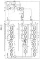
- FIG. 5 is a block diagram of a synchronization estimation apparatus according to an embodiment.
- a synchronization estimation apparatus includes a correlator 100 , a delayer 200 , and a synchronization estimator 300 .
- the correlator 100 may perform a correlation operation using a correlation window on a plurality of synchronization estimation signals separated to a plurality of paths, and output a plurality of correlated signals.
- Each of the plurality of synchronization estimation signals may be a bootstrap signal.
- Equation 3 r(k) represents a received bootstrap signal, x(k) represents a transmitted bootstrap signal, and w(k) represents a Gaussian noise. Further, f 0 represents a frequency domain error, and T S represents a sampling ratio for the bootstrap signal.
- the correlator 100 may perform an over-correlation operation on the first synchronization estimation signal 11 b among the plurality of synchronization estimation signals, perform a general correlation operation on the second synchronization estimation signal 12 b among the plurality of synchronization estimation signals, and perform an over-correlation operation on the third synchronization estimation signal 13 b among the plurality of synchronization estimation signals.
- the correlator 100 may include a first correlator 110 , a second correlator 120 , and a third correlator 130 .
- the first correlator 110 may perform an over-correlation operation on the first synchronization estimation signal 11 b separated to a first path 1 among a plurality of paths to generate a first correlated signal and output the first correlated signal 11 .
- the first correlator 110 may perform a moving sum operation on the first synchronization estimation signal 11 b by using a correlation window having a first length N X and a dividing operation for a result of the moving sum operation by a third length N C shorter than the first length.
- the first length N X is a preset and stored window length, and may be sufficiently longer than a second length N B and the third length N C .
- N X means an integer greater than the N B and the N C , and a correlation operation with a longer length may be performed through the value of N X .
- the third length N C may be shorter than the second length N B .
- the third length N C may be longer than or equal to the second length N B .
- the first synchronization estimation signal 11 b may be a correlated signal obtained by a correlation operation between the synchronization estimation signal 10 and a signal 11 a delayed by a preset interval from a synchronization estimation signal 10 .
- the preset interval for example, may be a fourth length N A shorter than the third length N C .
- the second correlator 120 may perform the general correlation operation on the second synchronization estimation signal 12 b separated to a second path 2 among the plurality of paths to generate a second correlated signal, and output the second correlated signal 12 .
- the second correlator 120 may perform a moving average operation on the second synchronization estimation signal 12 b by using a correlation window having the second length N B shorter than the first length N X .
- the second synchronization estimation signal 12 b may be a correlated signal obtained by a correlation operation between the synchronization estimation signal 10 and a signal 12 a delayed by a preset interval from a frequency-shifted synchronization estimation signal 10 .
- the preset interval for example, may be the second length N B . Since two consecutive same sample intervals are included in a correlation window when the correlation window having the first length N X is used by the second correlator 120 , the correlation window having the second length N B may be used.
- the third correlator 130 may perform an over-correlation operation on the third synchronization estimation signal 13 b among the plurality of synchronization estimation signals separated to a third route 3 among the plurality of paths to generate a third correlated signal, and output the third correlated signal 13 .
- the third correlator 130 may perform a moving sum operation on the third synchronization estimation signal 13 b by using a correlation window having the first length N X and a dividing operation for a result of the moving sum operation by the second length N B .
- the third synchronization estimation signal 13 b may be a correlated signal obtained by a correlation operation between the synchronization estimation signal 10 and a signal 13 a delayed by a preset interval from a frequency-shifted synchronization estimation signal 10 .
- the preset interval for example, may be a length obtained by adding the second length N B and the fourth length N A .
- the frequency-shifting operation may be performed by the second correlator 120 and the third correlator 130 according to a subcarrier interval.
- the structure of the bootstrap signal in the time domain may be considered.
- the first correlated signal 11 of the first path 1 may be expressed by Equation 4.
- Equation 4 ⁇ Denotes the phase rotation generated by f 0 , and ⁇ tilde over (w) ⁇ 1 (k,m) denotes the noise term that occurs when the Gaussian noise of Equation 3 is multiplied by the existing transmission signal terms.
- the second correlated signal 12 of the second path 2 may be expressed by Equation 5
- the third correlated signal 13 of the third path 3 may be expressed by Equation 6.
- FIG. 6 is a graph of a correlated signal in a synchronization estimation apparatus according to an embodiment.
- the first graph 6 a is a correlated signal in a synchronization device according to an embodiment.
- a triangular signal is output through a correlation operation in four identical sample intervals for all three paths by the synchronization device according to an embodiment.
- the synchronization device according to an embodiment may find one maximum value by sorting the correlated signals of the four identical sample intervals to estimate synchronization timing in the time domain.
- the triangular signal When the correlation operation is performed only in the same sample interval, the triangular signal may be output. Since the triangle-shaped result of the correlation operation has only one maximum value, the estimation of the synchronization timing may be less affected by noise than other types of the correlation operation.
- the second graph 6 b is a correlated signal in the synchronization estimation apparatus according to an embodiment. Since the synchronization estimation apparatus according to the embodiment employs a correlator using a longer length than the same sample length, a trapezoidal signal may be output. Since the correlation operation is performed for a longer interval, a trapezoidal signal may exhibit better performance in terms of SNR than the triangular signal.
- FIG. 7 is a graph illustrating alignment of correlated signals in a synchronization estimation apparatus according to an embodiment.
- the delayer 200 may delay the plurality of correlated signals to output a plurality of delayed signals.
- the delayer 200 may delay a plurality of correlated signals of which shape is trapezoid and output the plurality of delayed signals of which shape is triangle with a plurality of identical sample interval.
- the delayer 200 may delay the length of the upper side of the trapezoid for some of the same sample intervals among the plurality of identical sample intervals.
- the delayer 200 of the synchronization estimation apparatus may delay the same length as the synchronization apparatus in FIG. 4 for the first and third identical sample intervals. Then the delayer 200 of the synchronization estimation apparatus according to the embodiment may delay the length of the upper side of the trapezoid for the second and third identical sample intervals to output the triangular signal.
- the delayer 200 may include a first delayer 210 , a second delayer 220 , and a third delayer 230 .
- the first delayer 210 may perform an operation for delaying the first correlated signal 11 to generate a first delayed signal and output the first delayed signal 21 .
- the first delayed signal 21 is expressed by Equation 7.
- Corr S,A ( m ) 1 ⁇ 4 ⁇ Corr A ( m )+ Corr A ( m ⁇ N Sym )+ Corr A ( m ⁇ 2 N Sym )+ Corr A ( m ⁇ 3 N Sym ⁇ N B ) ⁇ [Equation 7]
- the second delayer 220 may perform an operation for delaying the second correlated signal 12 to generate a second delayed signal and output the second delayed signal 22 .
- the third delayer 230 may perform an operation for delaying the third correlated signal 13 to generate a third delayed signal and output the third delayed signal 23 .
- the delay operation or alignment operation by the delayer 200 may convert a trapezoidal correlated signal with improved SNR into a triangular-shaped signal which is advantageous for signal detection. Through this, the accuracy of the estimation can be improved.
- FIG. 8 is a diagram illustrating a correlation window when a maximum correlation value is output according to an embodiment.
- the synchronization estimation apparatus may perform a correlation operation for a longer interval in the first path 1 and the third path 3 than the synchronization apparatus in FIG. 4 .
- the synchronization estimator 300 may estimate the synchronization by using the plurality of delayed signals.
- the synchronization estimator 300 may include a first estimator 310 , a second estimator 320 , and a third estimator 330 .
- the first estimator 310 may perform a correlation operation on the third delayed signal 23 and the signal 31 a delayed from the second delayed signal to generate a first estimated signal, and output the first estimated signal 31 .
- the first estimated signal 31 may be expressed by Equation 10.
- Equation 10 shows a process of multiplying operation in which the correlated signals of the second path 2 and the third path 3 are delayed to be located the positions of the maximum correlation values.
- Corr 1 ( m ) ⁇ Corr S,B ( m ⁇ N A ) ⁇ * Corr S,A+B ( m ) [Equation 10]
- the second estimator 320 may perform a correlation operation on the first delayed signal 21 and the signal 32 a delayed from the first estimated signal 31 to generate a second estimated signal, and output the second estimated signal 32 .
- the second estimated signal 32 is expressed by Equation (11).
- Corr 2 ( m ) ⁇ Corr 1 ( m ⁇ ( N C ⁇ N B )) ⁇ * Corr S,A ( m ) [Equation 11]
- the multiplying operation on the correlated signals of the three paths makes the reduced area in a form of the triangle a form of a quadratic function while maintaining the position of the maximum correlation value. This can make timing estimation less sensitive to the noise.
- the synchronization estimation value in the time domain obtained by the synchronization estimation apparatus according to the embodiment may be used to determine an estimation value in the frequency domain.
- the third estimator 330 may estimate the synchronization in the time domain and the frequency domain by using the first estimated signal 31 and the second estimated signal 32 .
- Equation 12 represents a process of estimating the synchronization timing in the time domain through Equation 11
- Equation 13 represents a process of using the estimation value an estimate in the time domain for estimating the timing in the frequency domain.
- Equation 12 ⁇ circumflex over (m) ⁇ is an estimation value of the synchronization in the time domain obtained through the maximum correlation value, and ⁇ circumflex over (f) ⁇ 0 represents an estimation value of the synchronization in the frequency domain obtained through the phase of the maximum correlation value at the position of ⁇ circumflex over (m) ⁇ .
- the accuracy for estimation of the frequency domain can be improved.
- FIGS. 9 and 10 are flowcharts of a method for estimating the synchronization of the broadcast signal in the time domain according to an embodiment.
- the synchronization estimation method may include performing a correlation operation using a correlation window on a plurality of synchronization estimation signals separated to a plurality of paths and output a plurality of correlated signals (S 100 ). Further, the synchronization estimation method may include delaying the plurality of correlated signals to output a plurality of delayed signals (S 200 ), and estimating synchronization by using the plurality of delayed signals (S 300 ).
- the performing a correlation operation using a correlation window on a plurality of synchronization estimation signals separated to a plurality of paths and outputting a plurality of correlated signals includes: performing the over-correlation operation on the first synchronization estimation signal among the synchronization estimation signals; and performing the general correlation operation on the second synchronization estimation signal among the plurality of synchronization estimation signals.
- the performing of the over-correlation operation may be performing the moving sum operation on the first synchronization estimation signal by using a first correlation window having the first length.
- the performing of the general correlation operation may be performing the moving average operation on the second synchronization estimation signal by using a second correlation window having the second length shorter than the first length.
- the performing a correlation operation using a correlation window on a plurality of synchronization estimation signals separated to a plurality of paths and outputting a plurality of correlated signals may include performing the over-correlation operation on the first synchronization estimation signal separated to a first path among the plurality of paths to generate a first correlated signal and outputting the first correlated signal (S 110 ), performing the general correlation operation on the second synchronization estimation signal separated to a second path among the plurality of paths to generate a second correlated signal and outputting the second correlated signal (S 120 ), and performing the over-correlation operation on a third synchronization estimation signal among the plurality of synchronization estimation signals separated to a third path among the plurality of paths to generate a third correlated signal and outputting the third correlated signal (S 130 ).
- the over-correlation operation may correspond to a moving sum operation on the first synchronization estimation signal and the third synchronization estimation signal by using a first correlation window having a first length
- the general correlation operation may correspond to a moving average operation on a second synchronization estimation signal by using a second correlation window having a second length shorter than the first length
- a dividing operation for the result of the moving sum operation by the third length shorter than the first length may be performed.
- a dividing operation for the result of the moving sum operation by the second length may be performed.
- delaying the plurality of correlated signals of which shape is trapezoid and outputting the plurality of delayed signals of which shape is triangle with a plurality of identical sample interval may be performed.
- outputting a first delayed signal by delaying the first correlated signal, outputting a second delayed signal by delaying the second correlated signal, and outputting a third delayed signal by delaying the third correlated signal may be performed.
- performing a correlation operation on the third delayed signal and a signal delayed from the second delayed signal to generate a first estimated signal, and outputting the first estimated signal; and performing a correlation operation on a signal delayed from the first estimated signal and the first delayed signal to generate a second estimated signal, and outputting the second estimated signal may be performed.
- FIG. 11 is a block diagram of a synchronization estimation apparatus according to another embodiment.
- a computer system 1100 may include at least one of processor 1110 , a memory 1130 , an input interface unit 1150 , an output interface unit 1160 , and storage 1140 .
- the computer system 1100 may also include a communication unit 1120 coupled to a network.
- the processor 1110 may be a central processing unit (CPU) or a semiconductor device that executes instructions stored in the memory 1130 or storage 1140 .
- the memory 1130 and the storage 1140 may include various forms of volatile or non-volatile storage media.
- the memory may include read only memory (ROM) 1131 or random access memory (RAM) 1132 .
- the memory may be located inside or outside the processor, and the memory may be coupled to the processor through various means already known.
- the embodiments may be embodied as a computer-implemented method or as a non-volatile computer-readable medium having computer-executable instructions stored thereon.
- the computer-readable instructions when executed by a processor, the computer-readable instructions may perform the method according to at least one aspect of the present disclosure.
- the communication unit 1120 may transmit or receive a wired signal or a wireless signal.
- the embodiments are not implemented only by the apparatuses and/or methods described so far, but may be implemented through a program realizing the function corresponding to the configuration of the embodiment of the present disclosure or a recording medium on which the program is recorded.
- methods e.g., network management methods, data transmission methods, transmission schedule generation methods, etc.
- the computer-readable medium may include program instructions, data files, data structures, and the like, alone or in combination.
- the program instructions to be recorded on the computer-readable medium may be those specially designed or constructed for the embodiments of the present disclosure or may be known and available to those of ordinary skill in the computer software arts.
- the computer-readable recording medium may include a hardware device configured to store and execute program instructions.
- the computer-readable recording medium can be any type of storage media such as magnetic media like hard disks, floppy disks, and magnetic tapes, optical media like CD-ROMs, DVDs, magneto-optical media like floptical disks, and ROM, RAM, flash memory, and the like.
- Program instructions may include machine language code such as those produced by a compiler, as well as high-level language code that may be executed by a computer via an interpreter, or the like.
- the synchronizing estimation apparatus includes a processor 1110 and a memory 1130 , and the processor 1110 executes a program stored in the memory 1130 to perform: performing a correlation operation using a correlation window on a plurality of synchronization estimation signals separated to a plurality of paths and outputting a plurality of correlated signals; delaying the plurality of correlated signals to output a plurality of delayed signals; and estimating the synchronization using the plurality of delayed signals.
- the processor executes the program to perform an over-correlation operation on a first synchronization estimation signal among the plurality of synchronization estimation signals and a general correlation operation on a second synchronization estimation signal among the plurality of synchronization estimation signals.
Landscapes
- Engineering & Computer Science (AREA)
- Computer Networks & Wireless Communication (AREA)
- Signal Processing (AREA)
- Synchronisation In Digital Transmission Systems (AREA)
Abstract
Description
r(k)=x(k)e j2πf
Corr S,A(m)=¼{Corr A(m)+Corr A(m−N Sym)+Corr A(m−2N Sym)+Corr A(m−3N Sym −N B)} [Equation 7]
Corr S,B(m)=¼{Corr B(m)Corr B(m−N Sym)+Corr B(m−2N Sym)+Corr B(m−2N Sym−2N B)} [Equation 8]
Corr S,A+B(m)=¼{Corr A+B(m)−Corr A+B(m−N Sym)+Corr A+B(m−2N Sym)+Corr A+B(m−2N Sym −N A−2N B)} [Equation 9]
Corr 1(m)={Corr S,B(m−N A)}*Corr S,A+B(m) [Equation 10]
Corr 2(m)={Corr 1(m−(N C −N B))}*Corr S,A(m) [Equation 11]
Claims (20)
Applications Claiming Priority (2)
| Application Number | Priority Date | Filing Date | Title |
|---|---|---|---|
| KR1020190039805A KR20200117541A (en) | 2019-04-04 | 2019-04-04 | Apparatus and method for estimating time domain of broadcast signal |
| KR10-2019-0039805 | 2019-04-04 |
Publications (2)
| Publication Number | Publication Date |
|---|---|
| US20200322121A1 US20200322121A1 (en) | 2020-10-08 |
| US11190333B2 true US11190333B2 (en) | 2021-11-30 |
Family
ID=72663340
Family Applications (1)
| Application Number | Title | Priority Date | Filing Date |
|---|---|---|---|
| US16/839,916 Active US11190333B2 (en) | 2019-04-04 | 2020-04-03 | Apparatus and method for estimating synchronization of broadcast signal in time domain |
Country Status (2)
| Country | Link |
|---|---|
| US (1) | US11190333B2 (en) |
| KR (1) | KR20200117541A (en) |
Citations (7)
| Publication number | Priority date | Publication date | Assignee | Title |
|---|---|---|---|---|
| US20040105512A1 (en) * | 2002-12-02 | 2004-06-03 | Nokia Corporation | Two step synchronization procedure for orthogonal frequency division multiplexing (OFDM) receivers |
| US20110156954A1 (en) * | 2009-12-29 | 2011-06-30 | Texas Instruments Incorporated | Position and Velocity Uncertainty Metrics in GNSS Receivers |
| KR20120098347A (en) | 2011-02-28 | 2012-09-05 | 연세대학교 산학협력단 | Double correlator for estimating synchronization in broadcast service and broadcast apparatus including the same |
| KR101374378B1 (en) | 2013-01-22 | 2014-03-19 | 한국항공대학교산학협력단 | Ofdm based system time synchronization apparatus and method |
| US20140333836A1 (en) | 2011-10-18 | 2014-11-13 | Electronics And Telecommunications Research Institute | Apparatus and method for adding synchronization information to an auxiliary data space in a video signal and synchronizing a video |
| US20170163978A1 (en) | 2015-12-08 | 2017-06-08 | Electronics And Telecommunications Research Institute | System and method for synchronizing audio signal and video signal |
| EP3206391A1 (en) | 2014-10-12 | 2017-08-16 | LG Electronics Inc. | Broadcast signal transmission device, broadcast signal reception device, broadcast signal transmission method, and broadcast signal reception method |
-
2019
- 2019-04-04 KR KR1020190039805A patent/KR20200117541A/en not_active Application Discontinuation
-
2020
- 2020-04-03 US US16/839,916 patent/US11190333B2/en active Active
Patent Citations (7)
| Publication number | Priority date | Publication date | Assignee | Title |
|---|---|---|---|---|
| US20040105512A1 (en) * | 2002-12-02 | 2004-06-03 | Nokia Corporation | Two step synchronization procedure for orthogonal frequency division multiplexing (OFDM) receivers |
| US20110156954A1 (en) * | 2009-12-29 | 2011-06-30 | Texas Instruments Incorporated | Position and Velocity Uncertainty Metrics in GNSS Receivers |
| KR20120098347A (en) | 2011-02-28 | 2012-09-05 | 연세대학교 산학협력단 | Double correlator for estimating synchronization in broadcast service and broadcast apparatus including the same |
| US20140333836A1 (en) | 2011-10-18 | 2014-11-13 | Electronics And Telecommunications Research Institute | Apparatus and method for adding synchronization information to an auxiliary data space in a video signal and synchronizing a video |
| KR101374378B1 (en) | 2013-01-22 | 2014-03-19 | 한국항공대학교산학협력단 | Ofdm based system time synchronization apparatus and method |
| EP3206391A1 (en) | 2014-10-12 | 2017-08-16 | LG Electronics Inc. | Broadcast signal transmission device, broadcast signal reception device, broadcast signal transmission method, and broadcast signal reception method |
| US20170163978A1 (en) | 2015-12-08 | 2017-06-08 | Electronics And Telecommunications Research Institute | System and method for synchronizing audio signal and video signal |
Also Published As
| Publication number | Publication date |
|---|---|
| KR20200117541A (en) | 2020-10-14 |
| US20200322121A1 (en) | 2020-10-08 |
Similar Documents
| Publication | Publication Date | Title |
|---|---|---|
| JP4263119B2 (en) | Method and apparatus for initial frequency synchronization in OFDM system | |
| USRE44622E1 (en) | Coarse carrier frequency offset estimation for a receiver | |
| US8135079B2 (en) | Apparatus and method of estimating signal-to-noise ratio | |
| US9160597B2 (en) | Method for estimating OFDM integer frequency offset, OFDM integer frequency offset estimator and OFDM receiver system | |
| KR101376556B1 (en) | Detection of presence of television signals embedded in noise using cyclostationary toolbox | |
| US8073393B2 (en) | Methods and systems for least squares block channel estimation | |
| EP3796611B1 (en) | Phase calibration method and device | |
| JP5257249B2 (en) | Receiving apparatus, receiving method, program, and receiving system | |
| US9294312B2 (en) | Apparatus and method for estimating doppler spread in mobile communication system | |
| US8000415B2 (en) | Method and device for detecting a synchronization signal in a communication system | |
| US7529179B1 (en) | Joint maximum likelihood estimation of integer carrier frequency offset and channel in OFDM systems | |
| WO2016002106A1 (en) | Reception apparatus, reception method, and nontemporary computer readable medium | |
| US9184972B2 (en) | Frequency offset estimation method in OFDM system and OFDM receiver using the same | |
| US9042435B2 (en) | Transmitter and receiver for frequency domain equalization | |
| US8300717B2 (en) | Sampling frequency offset estimation apparatus and method of OFDM system | |
| US11190333B2 (en) | Apparatus and method for estimating synchronization of broadcast signal in time domain | |
| US10142150B2 (en) | Pilot signal generating apparatus, method thereof, and transmitting apparatus | |
| US7590184B2 (en) | Blind preamble detection for an orthogonal frequency division multiplexed sample stream | |
| US9137053B2 (en) | Apparatus and method of estimating channel in consideration of residual synchronization offset | |
| KR102558948B1 (en) | Method and apparatus for estimating carrier frequency offset of ofdm system using 1-bit adc | |
| KR102395353B1 (en) | Apparatus and method for decoding bootstrap signals | |
| JP6410747B2 (en) | Receiving apparatus and receiving method | |
| WO2012114413A1 (en) | Reception device | |
| KR20150025972A (en) | Method for self timing detection of frame synchronization | |
| US8824609B2 (en) | Receiving device and receiving method |
Legal Events
| Date | Code | Title | Description |
|---|---|---|---|
| FEPP | Fee payment procedure |
Free format text: ENTITY STATUS SET TO UNDISCOUNTED (ORIGINAL EVENT CODE: BIG.); ENTITY STATUS OF PATENT OWNER: SMALL ENTITY |
|
| AS | Assignment |
Owner name: ELECTRONICS AND TELECOMMUNICATIONS RESEARCH INSTITUTE, KOREA, REPUBLIC OF Free format text: ASSIGNMENT OF ASSIGNORS INTEREST;ASSIGNORS:BAEK, MYUNG-SUN;RA, SANG-JUNG;BAE, BYUNGJUN;AND OTHERS;REEL/FRAME:052320/0730 Effective date: 20200327 |
|
| FEPP | Fee payment procedure |
Free format text: ENTITY STATUS SET TO SMALL (ORIGINAL EVENT CODE: SMAL); ENTITY STATUS OF PATENT OWNER: SMALL ENTITY |
|
| STPP | Information on status: patent application and granting procedure in general |
Free format text: NON FINAL ACTION MAILED |
|
| STPP | Information on status: patent application and granting procedure in general |
Free format text: RESPONSE TO NON-FINAL OFFICE ACTION ENTERED AND FORWARDED TO EXAMINER |
|
| STPP | Information on status: patent application and granting procedure in general |
Free format text: NOTICE OF ALLOWANCE MAILED -- APPLICATION RECEIVED IN OFFICE OF PUBLICATIONS |
|
| STPP | Information on status: patent application and granting procedure in general |
Free format text: PUBLICATIONS -- ISSUE FEE PAYMENT VERIFIED |
|
| STCF | Information on status: patent grant |
Free format text: PATENTED CASE |