US11186355B2 - Morphing control surface - Google Patents
Morphing control surface Download PDFInfo
- Publication number
- US11186355B2 US11186355B2 US15/781,952 US201715781952A US11186355B2 US 11186355 B2 US11186355 B2 US 11186355B2 US 201715781952 A US201715781952 A US 201715781952A US 11186355 B2 US11186355 B2 US 11186355B2
- Authority
- US
- United States
- Prior art keywords
- mounting device
- profiled
- aerodynamic
- leaf spring
- profiled element
- Prior art date
- Legal status (The legal status is an assumption and is not a legal conclusion. Google has not performed a legal analysis and makes no representation as to the accuracy of the status listed.)
- Active, expires
Links
Images


Classifications
-
- B—PERFORMING OPERATIONS; TRANSPORTING
- B64—AIRCRAFT; AVIATION; COSMONAUTICS
- B64C—AEROPLANES; HELICOPTERS
- B64C23/00—Influencing air flow over aircraft surfaces, not otherwise provided for
- B64C23/06—Influencing air flow over aircraft surfaces, not otherwise provided for by generating vortices
- B64C23/065—Influencing air flow over aircraft surfaces, not otherwise provided for by generating vortices at the wing tips
-
- B—PERFORMING OPERATIONS; TRANSPORTING
- B64—AIRCRAFT; AVIATION; COSMONAUTICS
- B64C—AEROPLANES; HELICOPTERS
- B64C3/00—Wings
- B64C3/38—Adjustment of complete wings or parts thereof
- B64C3/44—Varying camber
- B64C3/50—Varying camber by leading or trailing edge flaps
-
- B—PERFORMING OPERATIONS; TRANSPORTING
- B64—AIRCRAFT; AVIATION; COSMONAUTICS
- B64C—AEROPLANES; HELICOPTERS
- B64C13/00—Control systems or transmitting systems for actuating flying-control surfaces, lift-increasing flaps, air brakes, or spoilers
- B64C13/24—Transmitting means
- B64C13/26—Transmitting means without power amplification or where power amplification is irrelevant
- B64C13/28—Transmitting means without power amplification or where power amplification is irrelevant mechanical
- B64C13/30—Transmitting means without power amplification or where power amplification is irrelevant mechanical using cable, chain, or rod mechanisms
-
- B—PERFORMING OPERATIONS; TRANSPORTING
- B64—AIRCRAFT; AVIATION; COSMONAUTICS
- B64C—AEROPLANES; HELICOPTERS
- B64C23/00—Influencing air flow over aircraft surfaces, not otherwise provided for
- B64C23/06—Influencing air flow over aircraft surfaces, not otherwise provided for by generating vortices
- B64C23/065—Influencing air flow over aircraft surfaces, not otherwise provided for by generating vortices at the wing tips
- B64C23/069—Influencing air flow over aircraft surfaces, not otherwise provided for by generating vortices at the wing tips using one or more wing tip airfoil devices, e.g. winglets, splines, wing tip fences or raked wingtips
- B64C23/076—Influencing air flow over aircraft surfaces, not otherwise provided for by generating vortices at the wing tips using one or more wing tip airfoil devices, e.g. winglets, splines, wing tip fences or raked wingtips the wing tip airfoil devices comprising one or more separate moveable members thereon affecting the vortices, e.g. flaps
-
- B—PERFORMING OPERATIONS; TRANSPORTING
- B64—AIRCRAFT; AVIATION; COSMONAUTICS
- B64C—AEROPLANES; HELICOPTERS
- B64C9/00—Adjustable control surfaces or members, e.g. rudders
- B64C9/02—Mounting or supporting thereof
-
- B—PERFORMING OPERATIONS; TRANSPORTING
- B64—AIRCRAFT; AVIATION; COSMONAUTICS
- B64C—AEROPLANES; HELICOPTERS
- B64C9/00—Adjustable control surfaces or members, e.g. rudders
- B64C9/08—Adjustable control surfaces or members, e.g. rudders bodily displaceable
-
- Y—GENERAL TAGGING OF NEW TECHNOLOGICAL DEVELOPMENTS; GENERAL TAGGING OF CROSS-SECTIONAL TECHNOLOGIES SPANNING OVER SEVERAL SECTIONS OF THE IPC; TECHNICAL SUBJECTS COVERED BY FORMER USPC CROSS-REFERENCE ART COLLECTIONS [XRACs] AND DIGESTS
- Y02—TECHNOLOGIES OR APPLICATIONS FOR MITIGATION OR ADAPTATION AGAINST CLIMATE CHANGE
- Y02T—CLIMATE CHANGE MITIGATION TECHNOLOGIES RELATED TO TRANSPORTATION
- Y02T50/00—Aeronautics or air transport
- Y02T50/10—Drag reduction
-
- Y—GENERAL TAGGING OF NEW TECHNOLOGICAL DEVELOPMENTS; GENERAL TAGGING OF CROSS-SECTIONAL TECHNOLOGIES SPANNING OVER SEVERAL SECTIONS OF THE IPC; TECHNICAL SUBJECTS COVERED BY FORMER USPC CROSS-REFERENCE ART COLLECTIONS [XRACs] AND DIGESTS
- Y02—TECHNOLOGIES OR APPLICATIONS FOR MITIGATION OR ADAPTATION AGAINST CLIMATE CHANGE
- Y02T—CLIMATE CHANGE MITIGATION TECHNOLOGIES RELATED TO TRANSPORTATION
- Y02T50/00—Aeronautics or air transport
- Y02T50/30—Wing lift efficiency
-
- Y—GENERAL TAGGING OF NEW TECHNOLOGICAL DEVELOPMENTS; GENERAL TAGGING OF CROSS-SECTIONAL TECHNOLOGIES SPANNING OVER SEVERAL SECTIONS OF THE IPC; TECHNICAL SUBJECTS COVERED BY FORMER USPC CROSS-REFERENCE ART COLLECTIONS [XRACs] AND DIGESTS
- Y02—TECHNOLOGIES OR APPLICATIONS FOR MITIGATION OR ADAPTATION AGAINST CLIMATE CHANGE
- Y02T—CLIMATE CHANGE MITIGATION TECHNOLOGIES RELATED TO TRANSPORTATION
- Y02T50/00—Aeronautics or air transport
- Y02T50/40—Weight reduction
Definitions
- the invention relates to an aerodynamic profiled body for an aircraft, particularly a winglet, which comprises a front profiled element with a profile leading edge and a rear profiled element with a profile trailing edge, as well as to an aircraft with such an aerodynamic profiled body.
- Aerodynamic profiled bodies are used in aircraft, wherein one common aspect of these aerodynamic profiled bodies is an outside surface in airflow. Aerodynamic profiled bodies are realized, for example, in the form of so-called winglets, which are less commonly referred to as wing end plates and mounted on the free ends of the aircraft wings in the form of attachments. Winglets reduce the aerodynamic drag of the wings. The winglets are available in various designs.
- profiled bodies significantly influences the fuel consumption of the aircraft just like their weight.
- noise development of the aircraft depends on the turbulences on the profiled bodies.
- EP 1 047 593 B1 proposes an aircraft wing, in which devices for varying the cross-sectional profile are provided on the leading edge and on the trailing edge.
- a flexible outer frame is provided and covered with a flexible skin.
- An actuator is provided on the rear section of the wing profile and acts upon a flexible connecting structure.
- the connecting structure features compressible S-shaped elements that are connected to the flexible outer frame. In this way, the profile of the trailing edge can be adapted.
- Another actuator is provided on the front section of the wing profile and exerts a radial force upon a connecting structure, wherein said radial force is transmitted to the flexible frame.
- the geometry of the leading edge can thereby also be adapted.
- the present invention is therefore based on the objective of diminishing or eliminating at least individual disadvantages of the prior art. Consequently, the invention particularly aims to enable an aerodynamic profiled body and an aircraft to adapt the profile geometry in-flight with constructively simple means and without significantly affecting the airflow around the profile.
- the invention is characterized by an adjusting unit that connects the front profiled element to the rear profiled element and by means of which the rear profiled element is adjustable relative to the front profiled element, wherein the adjusting unit comprises a front mounting device that is connected to the front profiled element, a rear mounting device that is connected to the rear profiled element and a force-transmitting device that connects the front mounting device and the rear mounting device to one another.
- the adjusting unit by means of which the profile geometry can be adapted in-flight, is accordingly arranged between the front profiled element and the rear profiled element.
- the adjusting unit is particularly designed for adapting the progression of the mean or center line (“camber”) of the profiled body.
- the front profiled element and the rear profiled element each may be essentially rigid. In the context of this disclosure, this means that the front and the rear profiled element are respectively subject to normal elastic deformations under a mechanical load, but no defined change in shape of the front or rear profiled element takes place for adapting the profile geometry.
- the shape of the adjusting unit between the front and the rear profiled element can be changed in order to adapt the profile geometry.
- the adjusting unit respectively comprises at least one front mounting device on the front profiled element and one rear mounting device on the rear profiled element.
- the angle of the rear mounting device relative to the front mounting device can be varied in order to adapt the profile geometry.
- the maximum angular variation between the front mounting device and the rear mounting device preferably amounts to at least several degrees.
- the force transmission between the rear profiled element and the front profiled element is realized with the force-transmitting device, by means of which a torque is applied to one of the mounting devices, particularly the rear mounting device.
- the aerodynamic profiled body is preferably a winglet that can be arranged on the end of a wing.
- the inventive adjusting unit can also be used on a control surface element, particularly a rudder or a spoiler.
- the geometry of the aerodynamic profiled body can be adapted with the aid of the adjusting unit, wherein an angle of the rear profiled element relative to the front profiled element particularly can be adjusted by several degrees, e.g. 10°, relative to a normal position. In the case of a winglet, this makes it possible to react to changing environmental conditions, e.g. wind gusts, by varying the profile geometry. In this way, the flight characteristics of a correspondingly equipped aircraft can be advantageously optimized.
- the profile geometry adaptation of the profiled body particularly makes it possible to achieve fuel savings. Depending on the application, the in-flight noise development can also be reduced.
- the force-transmitting device comprises an elastically deformable leaf spring element.
- the arrangement of the leaf spring element advantageously defines a bending line between the front and the rear profiled element.
- the cross-sectional profile can essentially extend continuously from the profile leading edge to the profile trailing edge.
- leaf spring element refers to a flexible element, the extension of which along a principal plane being several times greater than perpendicular thereto, particularly by a multiple.
- the adjusting unit comprises a drive, particularly a linear drive, for transmitting a torque to the force-transmitting device.
- the drive is preferably accommodated in the front profiled element.
- the linear drive may be realized in the form of a hydraulic or pneumatic cylinder-piston drive.
- DE 10 2009 053126 A1 describes an adjusting device for regulating flaps that are pivotably mounted on an aircraft wing.
- An actuator is coupled to a drive unit by means of a rotary driveshaft in order to transmit a torque to the regulating flap.
- the torque transmission is realized by connecting the actuator to a connecting device, which in turn is coupled to the regulating flap, by means of a coupling device.
- the angle of the regulating flap relative to the wing is therefore varied due to a rotation of the actuator.
- the actuator is arranged on the wing and connected to the coupling device by means of a first joint, wherein said coupling device is in turn connected to the regulating flap or the connecting device by means of a second joint.
- EP 0230681 A2 (DE 3643157 A1) describes a different type of device for pivoting a slat that is arranged on the leading edge of an aircraft wing.
- the slat essentially can be arranged in three positions: retracted ( FIG. 1 ), extended ( FIG. 3 ), as well as extended and pivoted ( FIG. 6 ).
- the changeover between the first position ( FIG. 1 ) and the second position ( FIG. 3 ) is realized due to a motion of the slat along a main carrier rail, wherein this motion is driven by a rotary actuating arrangement. In this case, the slat is moved forward (in the direction of flight) and a downward.
- a spring pretensioning device is designed for holding the slat in this position with the aid of a certain spring force.
- a pivoting motion of the slat takes place when the aerodynamic force becomes greater than the spring force due to the inflowing air, wherein the slat is additionally pivoted downward in this case such that the curvature of the wing increases.
- the motion/pivoting motion of the slat is accordingly realized mechanically (rotary actuating arrangement) in a first step and due to the fact that the aerodynamic forces exceed the spring force of the spring pretensioning device in a second step.
- the spring pretensioning device comprises layered leaf springs.
- the leaf springs in EP 0230681 A2 are designed for a completely different purpose and therefore also exhibit numerous constructive differences.
- EP 0230681 A2 lacks the drive provided in the above-described embodiment for transmitting a torque to the force-transmitting device.
- the leaf spring assembly is merely deformed passively—by the inflowing air.
- DE 19503051 A1 discloses a linear drive for adjusting a wing flap that comprises an input part and an output part coupled thereto. If the motion of the wing flap is blocked due to external influences and a certain limiting value for the force transmitted to the wing flap is exceeded, the input part is decoupled from the output part such that the force transmission is interrupted. Consequently, DE 19503051 A1 pertains to a safety device of sorts for a linear drive unit (as an alternative to torque limiters or predetermined breaking points).
- the adjusting unit is preferably capable of deforming the leaf spring element in a direction essentially perpendicular to the principal plane of the leaf spring element.
- the adjusting unit between the front and the rear profiled element can be actuated in order to adapt the profile geometry of the aerodynamic profiled body to the prevailing ambient conditions.
- the leaf spring element is bent open in a direction essentially perpendicular to its principal plane due to the actuation of the adjusting unit. In the bent-open state of the leaf spring element, an essentially uniform force transmission between the front and the rear mounting device is achieved along the principal plane of the leaf spring element.
- the leaf spring element in a normal position of the rear profiled element is essentially arranged plane relative to the front profiled element, wherein in an active position of the rear profiled element the leaf spring element is essentially bent open in a direction perpendicular to the principal plane of the leaf spring element.
- the leaf spring element is essentially arranged centrally between a profile upper side and a profile underside. Accordingly, the cross section of the leaf spring element is in this embodiment essentially arranged along the profile center line, which is frequently also referred to as mean line or curvature line.
- the leaf spring element defines a bending line between the front profiled element and the rear profiled element. Savings in the kerosene consumption, as well as a reduced noise development, can be advantageously achieved with this embodiment.
- the leaf spring element is made of fiber-reinforced plastic, particularly of carbon fiber-reinforced plastic.
- This embodiment is characterized by a high flexural strength, a precisely defined force path, little maintenance effort and a low weight.
- the front mounting device comprises an elongate recess for receiving one end of the leaf spring element and the rear mounting device comprises an elongate recess for receiving the other end of the leaf spring element.
- the drive is connected to the two force-transmitting devices by means of a fork element.
- the fork element may comprise multiple recesses in order to reduce the weight of the adjusting unit.
- the force-transmitting device comprises a lever mechanism, which is respectively connected to the front mounting device and the rear mounting device, for transmitting a torque to the front or the rear mounting device.
- the torque is preferably transmitted to the rear mounting device in order to adjust the rear profiled element relative to the front profiled element.
- the lever mechanism may alternatively also be designed for transmitting a torque to the front mounting device. In both embodiments, a torque is applied to the lever mechanism, which in turn causes an adjustment of the relative angular position between the rear mounting device on the rear profiled element and the front mounting device on the front profiled element.
- the drive is connected to the lever mechanism, particularly by means of the fork element.
- the lever mechanism comprises a first connecting arm and a second connecting arm, the first ends of which are connected to the front or rear mounting device in an articulated fashion and the other ends of which are connected to the ends of a bearing lever in an articulated fashion, wherein said bearing lever is respectively mounted on the rear or the front mounting device in an articulated fashion.
- the connections may be made to enable components to move with respect to each other or articulate.
- the bearing lever is pivotably mounted on the front or on the rear mounting device by means of a stationary joint. The ends of the bearing lever are coupled to the first and the second connecting arm, which are mounted on the opposite mounting device, i.e. on the rear or on the front mounting device, by means of stationary joints.
- the bearing lever When the adjusting unit is actuated, the bearing lever is pivoted about its stationary joint, wherein the joints of the first and the second connecting arm on the bearing lever are displaced in opposite directions. Depending on the pivoting direction of the bearing lever, a compressive force is applied to the respective mounting device with the first connecting arm and a tensile force is applied to the respective mounting device by the second connecting arm (or vice versa). In this way, a torque is applied to this mounting device and causes a change in the angular position of the rear profiled element relative to the front profiled element.
- the adjusting unit comprises a housing with an upper outside surface that essentially ends flush with the profile upper side and a lower outside surface that essentially ends flush with the profile underside.
- the housing may be elastically deformable on the upper or lower outside surface in order to compensate deformations when the adjusting unit is actuated.
- the housing may alternatively be realized with essentially rigid outside surfaces, wherein the outside surfaces can respectively slide underneath the profile upper side or profile underside of the front and the rear profiled element in this case.
- the aerodynamic profiled body may be covered with a flexible film that, however, has a sufficient inherent rigidity as it is generally known from the prior art.
- the adjusting unit is separably connected to the front profiled element and the rear profiled element. This particularly means that the housing of the adjusting unit is not realized integrally with the front or the rear profiled element.
- the front mounting device is preferably mounted on the rear side of the front profiled element.
- the rear mounting device is mounted on the front side of the rear profiled element.
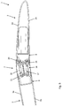
- FIG. 1 shows a graphical representation of an inventive profiled body in the form of a winglet for an aircraft, wherein an adjusting unit for adapting the profile geometry of the winglet is arranged between a front profiled element and a rear profiled element;
- FIG. 2 shows a representation of the winglet in a normal position
- FIG. 3 shows a representation of a winglet according to FIG. 2 in a first active position, in which the rear profiled element is adjusted by ⁇ 10° referred to the normal position;
- FIG. 4 shows a representation of the winglet according to FIGS. 2, 3 in a second active position, in which the rear profiled element is pivoted by +10° referred to the normal position;
- FIG. 5 shows a top view of the winglet in the region of the adjusting unit, the housing of which was omitted in order to provide a better overview
- FIG. 6 shows a detailed view of the adjusting unit without housing
- FIG. 7 shows another representation of the adjusting unit without housing in the mounted state on the rear profiled element
- FIG. 8 shows a cross section through the aerodynamic profiled body in the region of the adjusting unit in the normal position according to FIG. 2 ;
- FIG. 9 shows a cross section through the aerodynamic profiled body in the region of the adjusting unit in the first active position according to FIG. 3 ;
- FIG. 10 shows a cross section through the aerodynamic profiled body in the region of the adjusting unit in the second active position according to FIG. 4 .
- the drawings show an aerodynamic profiled body 1 , which is realized in the form of a winglet in this embodiment.
- the profiled body 1 comprises a front profiled element 2 , which is immovably arranged on the aircraft in the intended operational state of the profiled body 1 .
- the profiled body 1 also comprises a rear profiled element 3 , which is movably arranged relative to the front profiled element 2 in the intended operational state of the profiled body 1 .
- the front profiled element 2 has a front profile upper side 2 a in airflow and a front profile underside 2 b and the rear profiled element 3 has a rear profile upper side 3 a in airflow and a rear profile underside 3 b .
- a profile leading edge 4 a is formed on the front profiled element 2 and a profile trailing edge 5 a is formed on the rear profiled element 3 .
- the front profiled element 2 and the rear profiled element 3 are arranged in such a way that the rear profiled element 3 has an additional profile leading edge 4 b , which adjoins the profile leading edge 4 of the front profiled element 2 , and the front profiled element 2 has an additional profile trailing edge 5 b , which adjoins the profile trailing edge 5 of the rear profiled element 3 .
- FIGS. 1-5 show that an adjusting unit 7 is arranged between the front profiled element 2 and the rear profiled element 3 , wherein the rear profiled element 3 can be adjusted relative to the front profiled element 2 by means of said adjusting unit.
- the adjusting unit 7 extends angular to the profile leading edge 4 a , 4 b and to the profile trailing edge 5 a , 5 b , in particular in a direction essentially perpendicular to the principal plane of the (not-shown) wing.
- the adjusting unit 7 comprises at least one front mounting device 8 , which is connected to the front profiled element 2 , and one rear mounting device 9 , which is connected to the rear profiled element 3 .
- the front mounting device 8 is immovably mounted on the front profiled element 2 and the rear mounting device 9 is movably mounted on the rear profiled element 3 .
- two front mounting devices 8 are provided on the front profiled element 2 and two rear mounting devices 8 are provided on the rear profiled element 3 , wherein the two front and the two rear mounting devices are respectively spaced apart from one another in the longitudinal direction of the profiled body 1 .
- a force-transmitting device 10 is respectively arranged between each front mounting device 8 and rear mounting device 9 .
- the adjusting unit 7 is respectively connected separably to the front profiled element 2 and the rear profiled element 3 in a non-inseparable fashion.
- each force-transmitting device 10 comprises a flexible leaf spring element 11 that can be elastically deformed in a direction essentially perpendicular to the principal plane of the leaf spring element 11 .
- the leaf spring element 11 is essentially arranged centrally between a profile upper side and a profile underside.
- the leaf spring element 11 is made of fiber-reinforced plastic, particularly of carbon fiber-reinforced plastic.
- the front mounting device 8 comprises an elongate recess for receiving one end of the leaf spring element 11 and the rear mounting device 9 comprises a corresponding elongate recess for receiving the other end of the leaf spring element 11 . In this way, the ends of the leaf spring element 11 are clamped between the mounting devices.
- the leaf spring element 11 is freely flexural between the fixing points on its ends.
- FIGS. 1-5 show that a drive 12 is provided for transmitting a torque to the force-transmitting device 10 , wherein the drive is realized in the form of an individual linear cylinder-piston drive in the embodiment shown.
- the drive 12 is mounted on a first mounting rail 13 , on which one of the front mounting devices 8 is also supported.
- a second mounting rail 14 is provided, on which the other front mounting device 8 is supported. Accordingly, one front mounting device 8 is connected to the first mounting rail 13 and the other front mounting device 13 is connected to the second mounting rail 14 .
- the drive 12 is connected to the two force-transmitting devices 10 by means of a rigid fork element 15 . In the embodiment shown, the drive 12 essentially engages centrally on the fork element 15 .
- FIGS. 1-5 furthermore show that each force-transmitting device 10 comprises a lever mechanism 16 , which is respectively connected to the front mounting device 8 and the rear mounting device 9 , in order to transmit a torque to the rear mounting devices 9 .
- the drive 12 is connected to the lever mechanism 16 by means of the fork element 15 .
- the lever mechanism 16 features a first connecting arm 17 and a second connecting arm 18 . The first ends of the first connecting arm 17 and the second connecting arm 18 are connected to the rear mounting device 9 in an articulated fashion.
- first connecting arm 17 and the second connecting arm 18 are connected to the ends of a bearing lever 19 in an articulated fashion, wherein said bearing lever is mounted on the front mounting device 8 by means of a stationary joint 20 (referred to the front mounting device 8 ).
- the drive 12 engages on the fork element 15 such that the fork element 15 can be displaced essentially parallel to the principal plane of the leaf spring element 11 as a result of a linear advance of the drive 12 . Due to the displacement of the fork element 15 , the bearing lever 19 , which is connected thereto in an articulated fashion, is pivoted about the joint 20 .
- an effort arm is formed between the joint 20 and the articulated connection between the fork element 15 and the bearing lever 19 such that the angular position of the rear mounting device 9 is adjusted relative to the front mounting device 8 , for example, by an angle of more than 3°, preferably more than 5°, especially more than 8°, in particular essentially 10°.
- the joint 20 between the bearing lever 19 and the front mounting device 8 is essentially arranged in the principal plane of the leaf spring element 11 .
- FIGS. 8-10 The change in the relative position between the front mounting device 8 and the rear mounting device 9 can be gathered from FIGS. 8-10 .
- the front mounting devices 8 and the rear mounting devices 9 are arranged opposite of one another in pairs and essentially parallel to one another.
- the leaf spring element 11 is in a relaxed, plane state that corresponds to the normal position of the rear profiled element 3 relative to the front profiled element 2 .
- the rear mounting device 9 is arranged relative to the front mounting device 8 at an angle of essentially 10° such that the profiled body 1 is in the first active position.
- the leaf spring element 11 is in a state, in which it is bent open in a direction perpendicular to the principal plane of the leaf spring element 11 in one direction.
- the rear mounting device 9 is likewise arranged relative to the front mounting device 8 at an angle of 10°, however, referred to the other direction such that the profiled body 1 is in the second active position.
- the leaf spring element 11 is in a state, in which it is bent in the other direction open perpendicular to the principal plane of the leaf spring element.
- FIGS. 8-10 schematically show that the adjusting unit 7 features a housing with an upper outside surface 22 , which essentially ends flush with the profile upper side, and a lower outside surface 23 , which essentially ends flush with the profile underside.
- the location and direction information refers to the installed operational state of the aerodynamic profiled body 1 , in which the airflow is directed from the profile leading edge 4 a , 4 b to the profile trailing edge 5 a , 5 b.
Landscapes
- Engineering & Computer Science (AREA)
- Aviation & Aerospace Engineering (AREA)
- Mechanical Engineering (AREA)
- Automation & Control Theory (AREA)
- Springs (AREA)
- Vibration Prevention Devices (AREA)
- Structures Of Non-Positive Displacement Pumps (AREA)
- Current-Collector Devices For Electrically Propelled Vehicles (AREA)
- Connection Of Plates (AREA)
- Tires In General (AREA)
Abstract
Description
Claims (15)
Applications Claiming Priority (3)
| Application Number | Priority Date | Filing Date | Title |
|---|---|---|---|
| ATA50383/2016 | 2016-04-29 | ||
| ATA50383/2016A AT518606A1 (en) | 2016-04-29 | 2016-04-29 | Aerodynamic profile body for an aircraft |
| PCT/AT2017/060112 WO2017185121A1 (en) | 2016-04-29 | 2017-04-28 | Aerodynamic profiled body for an aircraft |
Publications (2)
| Publication Number | Publication Date |
|---|---|
| US20180362148A1 US20180362148A1 (en) | 2018-12-20 |
| US11186355B2 true US11186355B2 (en) | 2021-11-30 |
Family
ID=58707258
Family Applications (1)
| Application Number | Title | Priority Date | Filing Date |
|---|---|---|---|
| US15/781,952 Active 2039-02-03 US11186355B2 (en) | 2016-04-29 | 2017-04-28 | Morphing control surface |
Country Status (9)
| Country | Link |
|---|---|
| US (1) | US11186355B2 (en) |
| EP (1) | EP3448750B1 (en) |
| CN (1) | CN108463405B (en) |
| AT (1) | AT518606A1 (en) |
| BR (1) | BR112018013715B1 (en) |
| CA (1) | CA3006815C (en) |
| ES (1) | ES2780853T3 (en) |
| RU (1) | RU2698600C1 (en) |
| WO (1) | WO2017185121A1 (en) |
Families Citing this family (3)
| Publication number | Priority date | Publication date | Assignee | Title |
|---|---|---|---|---|
| EP3446964A1 (en) * | 2017-08-21 | 2019-02-27 | Claverham Limited | Control surface attachment |
| WO2020127609A1 (en) * | 2018-12-20 | 2020-06-25 | Airbus Operations Limited | Wingtip device for an aircraft |
| DE102024126857A1 (en) * | 2024-09-18 | 2026-03-19 | Airbus Operations Gmbh | Actuating system for operating an aircraft control surface, associated control surface arrangement, aircraft and operating procedure |
Citations (21)
| Publication number | Priority date | Publication date | Assignee | Title |
|---|---|---|---|---|
| US3478987A (en) | 1966-06-20 | 1969-11-18 | Giravions Dorand | Jet flaps |
| DE3643157A1 (en) | 1985-12-30 | 1987-07-02 | Boeing Co | PRELOADED FRONT EDGE LEVER |
| DE19503051A1 (en) | 1995-02-01 | 1996-08-08 | Zahnradfabrik Friedrichshafen | Linear drive for the adjustment of an element, in particular a wing element on an aircraft |
| US5947422A (en) | 1997-04-29 | 1999-09-07 | Mcdonnell Douglas | Tail for an aircraft |
| JP2001080589A (en) | 1999-09-17 | 2001-03-27 | Advanced Technology Inst Of Commuter Helicopter Ltd | Flap hinge mechanism, method of manufacturing the same, and flap hinge device |
| EP1205383A2 (en) | 2000-11-11 | 2002-05-15 | EADS Deutschland Gmbh | Mechanism for modifying the camber of at least a part of an aircraft wing |
| US20020100839A1 (en) | 2001-01-26 | 2002-08-01 | Miller Todd Scott | Model airplane hinge construction |
| US20050133672A1 (en) | 2003-11-10 | 2005-06-23 | Jan Irving | Wing tip device |
| EP1047593B1 (en) | 1998-01-15 | 2006-11-29 | Sridhar Kota | System for varying a surface contour |
| CN101098815A (en) | 2004-11-23 | 2008-01-02 | 空中巴士德国有限责任公司 | Devices for reducing aerodynamic noise on additional wings of aircraft |
| US20090200431A1 (en) | 2007-11-07 | 2009-08-13 | Konings Christopher A | Aircraft wing tip having a variable incidence angle |
| DE102009053126A1 (en) | 2009-11-13 | 2011-05-19 | Airbus Operations Gmbh | Control system of an aircraft with a valve |
| US7975965B2 (en) | 2008-05-13 | 2011-07-12 | The Boeing Company | Wing tip joint in airfoils |
| US20110253832A1 (en) * | 2010-04-13 | 2011-10-20 | Airbus Operations Limited | Slat support assembly |
| US20120091283A1 (en) * | 2010-10-18 | 2012-04-19 | Honda Patents & Technologies North America Llc | Aircraft control surface operating device |
| US20130001367A1 (en) * | 2009-12-10 | 2013-01-03 | Michael Frederick Boer | Method for reducing in fligt wake vortices and an aircraft wingtip arrangement used in such method |
| CN104670478A (en) | 2013-10-17 | 2015-06-03 | 波音公司 | Wingtip Control System |
| FR3014410A1 (en) | 2013-12-11 | 2015-06-12 | Airbus Operations Sas | AIRCRAFT HINGE BETWEEN A MOBILE PANEL AND A CARRIER STRUCTURE |
| US20160009378A1 (en) * | 2013-12-04 | 2016-01-14 | Tamarack Aerospace Group, Inc. | Adjustable lift modification wingtip |
| US20160244153A1 (en) * | 2014-08-13 | 2016-08-25 | The Boeing Company | Rotatable wing tip joint and method of making same |
| US20160264232A1 (en) * | 2015-03-09 | 2016-09-15 | Airbus Operations Limited | Aircraft comprising a foldable aerodynamic structure and an articulation mechanism for a foldable aerodynamic structure |
Family Cites Families (2)
| Publication number | Priority date | Publication date | Assignee | Title |
|---|---|---|---|---|
| SU1762488A1 (en) * | 1990-01-30 | 1994-04-30 | Центральный аэрогидродинамический институт им.проф.Н.Е.Жуковского | Adaptive wing |
| AT505901B1 (en) * | 2008-04-02 | 2009-05-15 | Facc Ag | CEILING PANEL FOR THE COVERING OF THE INTERIOR OF VEHICLES |
-
2016
- 2016-04-29 AT ATA50383/2016A patent/AT518606A1/en not_active Application Discontinuation
-
2017
- 2017-04-28 CA CA3006815A patent/CA3006815C/en active Active
- 2017-04-28 US US15/781,952 patent/US11186355B2/en active Active
- 2017-04-28 ES ES17723241T patent/ES2780853T3/en active Active
- 2017-04-28 CN CN201780006456.0A patent/CN108463405B/en active Active
- 2017-04-28 EP EP17723241.0A patent/EP3448750B1/en active Active
- 2017-04-28 WO PCT/AT2017/060112 patent/WO2017185121A1/en not_active Ceased
- 2017-04-28 BR BR112018013715-4A patent/BR112018013715B1/en active IP Right Grant
- 2017-04-28 RU RU2018124982A patent/RU2698600C1/en active
Patent Citations (28)
| Publication number | Priority date | Publication date | Assignee | Title |
|---|---|---|---|---|
| GB1174497A (en) | 1966-06-20 | 1969-12-17 | Giravions Dorand | Jet Flaps. |
| US3478987A (en) | 1966-06-20 | 1969-11-18 | Giravions Dorand | Jet flaps |
| DE3643157A1 (en) | 1985-12-30 | 1987-07-02 | Boeing Co | PRELOADED FRONT EDGE LEVER |
| EP0230681B1 (en) | 1985-12-30 | 1990-01-24 | The Boeing Company | Biased leading edge slat apparatus |
| DE19503051A1 (en) | 1995-02-01 | 1996-08-08 | Zahnradfabrik Friedrichshafen | Linear drive for the adjustment of an element, in particular a wing element on an aircraft |
| US5947422A (en) | 1997-04-29 | 1999-09-07 | Mcdonnell Douglas | Tail for an aircraft |
| EP1047593B1 (en) | 1998-01-15 | 2006-11-29 | Sridhar Kota | System for varying a surface contour |
| JP2001080589A (en) | 1999-09-17 | 2001-03-27 | Advanced Technology Inst Of Commuter Helicopter Ltd | Flap hinge mechanism, method of manufacturing the same, and flap hinge device |
| US6474945B1 (en) * | 1999-09-17 | 2002-11-05 | Advanced Technology Institute Of Commuter Helicopter, Ltd. | Flap hinge mechanism, method for manufacturing the same, and flap hinge apparatus |
| EP1205383A2 (en) | 2000-11-11 | 2002-05-15 | EADS Deutschland Gmbh | Mechanism for modifying the camber of at least a part of an aircraft wing |
| US20020100839A1 (en) | 2001-01-26 | 2002-08-01 | Miller Todd Scott | Model airplane hinge construction |
| US20050133672A1 (en) | 2003-11-10 | 2005-06-23 | Jan Irving | Wing tip device |
| CN101098815A (en) | 2004-11-23 | 2008-01-02 | 空中巴士德国有限责任公司 | Devices for reducing aerodynamic noise on additional wings of aircraft |
| US20090200431A1 (en) | 2007-11-07 | 2009-08-13 | Konings Christopher A | Aircraft wing tip having a variable incidence angle |
| US7975965B2 (en) | 2008-05-13 | 2011-07-12 | The Boeing Company | Wing tip joint in airfoils |
| DE102009053126A1 (en) | 2009-11-13 | 2011-05-19 | Airbus Operations Gmbh | Control system of an aircraft with a valve |
| CN102791574A (en) | 2009-11-13 | 2012-11-21 | 空中客车运作有限责任公司 | Flap adjustment system for aircraft with adjustable flaps |
| US8746625B2 (en) | 2009-11-13 | 2014-06-10 | Airbus Operations Gmbh | Flap adjusting system of an aircraft with a regulating flap |
| US20130001367A1 (en) * | 2009-12-10 | 2013-01-03 | Michael Frederick Boer | Method for reducing in fligt wake vortices and an aircraft wingtip arrangement used in such method |
| US20110253832A1 (en) * | 2010-04-13 | 2011-10-20 | Airbus Operations Limited | Slat support assembly |
| US20120091283A1 (en) * | 2010-10-18 | 2012-04-19 | Honda Patents & Technologies North America Llc | Aircraft control surface operating device |
| CN104670478A (en) | 2013-10-17 | 2015-06-03 | 波音公司 | Wingtip Control System |
| US20160009378A1 (en) * | 2013-12-04 | 2016-01-14 | Tamarack Aerospace Group, Inc. | Adjustable lift modification wingtip |
| FR3014410A1 (en) | 2013-12-11 | 2015-06-12 | Airbus Operations Sas | AIRCRAFT HINGE BETWEEN A MOBILE PANEL AND A CARRIER STRUCTURE |
| US20150166171A1 (en) | 2013-12-11 | 2015-06-18 | Airbus Operations (S.A.S.) | Aircraft hinge arranged between a movable panel and a load-bearing structure |
| US9604716B2 (en) | 2013-12-11 | 2017-03-28 | Airbus Operations (S.A.S.) | Aircraft hinge arranged between a movable panel and a load-bearing structure |
| US20160244153A1 (en) * | 2014-08-13 | 2016-08-25 | The Boeing Company | Rotatable wing tip joint and method of making same |
| US20160264232A1 (en) * | 2015-03-09 | 2016-09-15 | Airbus Operations Limited | Aircraft comprising a foldable aerodynamic structure and an articulation mechanism for a foldable aerodynamic structure |
Non-Patent Citations (3)
| Title |
|---|
| China National Intellectual Property Administration, Office Action and Search Report Issued in Application No. 201780006456.0, dated Aug. 23, 2021, 15 pages. |
| China National Intellectual Property Administration, Office Action and Search Report Issued in Application No. 201780006456.0, dated Jan. 5, 2021, 16 pages. |
| ISA European Patent Office, International Search Report Issued in Application No. PCT/AT2017/060112, dated Aug. 2, 2017, WIPO, 6 pages. |
Also Published As
| Publication number | Publication date |
|---|---|
| BR112018013715B1 (en) | 2023-11-28 |
| CN108463405A (en) | 2018-08-28 |
| EP3448750B1 (en) | 2020-01-01 |
| EP3448750A1 (en) | 2019-03-06 |
| ES2780853T3 (en) | 2020-08-27 |
| CA3006815C (en) | 2021-01-12 |
| CA3006815A1 (en) | 2017-11-02 |
| RU2698600C1 (en) | 2019-08-28 |
| US20180362148A1 (en) | 2018-12-20 |
| CN108463405B (en) | 2022-04-05 |
| AT518606A1 (en) | 2017-11-15 |
| BR112018013715A2 (en) | 2018-12-11 |
| WO2017185121A1 (en) | 2017-11-02 |
Similar Documents
| Publication | Publication Date | Title |
|---|---|---|
| CA2857892C (en) | Adaptive trailing edge actuator system and method | |
| EP2319759B1 (en) | Aircraft control surface | |
| US9079655B2 (en) | System for increasing controllability for an aircraft | |
| US9334043B2 (en) | Wing assembly with a main wing and movable high-lift body and a method for adjusting a high-lift body relative to a main wing | |
| US7665796B2 (en) | Functional device with pivotable element | |
| US9233749B1 (en) | Variable camber adaptive compliant wing system | |
| CN105980701B (en) | Device for strain relief on rotor blades of a wind turbine | |
| US8517315B2 (en) | Lateral coupling device for holding and guiding at least one aerodynamic body relative to the main wing of an aircraft, airfoil and aircraft with such a lateral coupling device | |
| US9315256B2 (en) | Flap arrangement and aircraft with at least one flap arrangement | |
| US20100320332A1 (en) | Spoiler for an aerodynamic body of an aircraft | |
| US11186355B2 (en) | Morphing control surface | |
| US9896188B1 (en) | Variable camber adaptive compliant wing system | |
| EP3524516B1 (en) | Linkage mechanism for linking a flaperon to a droop panel of an aircraft | |
| US8282038B2 (en) | Bi-directional flight control surface utilizing a split-track mechanism | |
| CN110871885B (en) | Wing systems for aircraft with fluid bodies and covering panels | |
| US8925869B2 (en) | Aerodynamic body with an ancillary flap | |
| CN117227964B (en) | Multi-connecting-rod variable-structure wing and aircraft | |
| EP2238024B1 (en) | Aircraft structure with modified control device hinge line |
Legal Events
| Date | Code | Title | Description |
|---|---|---|---|
| FEPP | Fee payment procedure |
Free format text: ENTITY STATUS SET TO UNDISCOUNTED (ORIGINAL EVENT CODE: BIG.); ENTITY STATUS OF PATENT OWNER: LARGE ENTITY |
|
| STPP | Information on status: patent application and granting procedure in general |
Free format text: APPLICATION DISPATCHED FROM PREEXAM, NOT YET DOCKETED |
|
| AS | Assignment |
Owner name: FACC AG, AUSTRIA Free format text: ASSIGNMENT OF ASSIGNORS INTEREST;ASSIGNORS:FILSEGGER, HERMANN;STEPHAN, WALTER;SIGNING DATES FROM 20180123 TO 20180126;REEL/FRAME:047111/0540 |
|
| STPP | Information on status: patent application and granting procedure in general |
Free format text: DOCKETED NEW CASE - READY FOR EXAMINATION |
|
| STPP | Information on status: patent application and granting procedure in general |
Free format text: NON FINAL ACTION MAILED |
|
| STPP | Information on status: patent application and granting procedure in general |
Free format text: RESPONSE TO NON-FINAL OFFICE ACTION ENTERED AND FORWARDED TO EXAMINER |
|
| STPP | Information on status: patent application and granting procedure in general |
Free format text: NOTICE OF ALLOWANCE MAILED -- APPLICATION RECEIVED IN OFFICE OF PUBLICATIONS |
|
| STPP | Information on status: patent application and granting procedure in general |
Free format text: AWAITING TC RESP., ISSUE FEE NOT PAID |
|
| STPP | Information on status: patent application and granting procedure in general |
Free format text: NOTICE OF ALLOWANCE MAILED -- APPLICATION RECEIVED IN OFFICE OF PUBLICATIONS |
|
| STPP | Information on status: patent application and granting procedure in general |
Free format text: PUBLICATIONS -- ISSUE FEE PAYMENT VERIFIED |
|
| STCF | Information on status: patent grant |
Free format text: PATENTED CASE |
|
| MAFP | Maintenance fee payment |
Free format text: PAYMENT OF MAINTENANCE FEE, 4TH YEAR, LARGE ENTITY (ORIGINAL EVENT CODE: M1551); ENTITY STATUS OF PATENT OWNER: LARGE ENTITY Year of fee payment: 4 |