US11184848B2 - Connected discontinuous reception wake up procedure - Google Patents
Connected discontinuous reception wake up procedure Download PDFInfo
- Publication number
- US11184848B2 US11184848B2 US16/032,742 US201816032742A US11184848B2 US 11184848 B2 US11184848 B2 US 11184848B2 US 201816032742 A US201816032742 A US 201816032742A US 11184848 B2 US11184848 B2 US 11184848B2
- Authority
- US
- United States
- Prior art keywords
- specific reference
- data
- base station
- signal
- reference signals
- Prior art date
- Legal status (The legal status is an assumption and is not a legal conclusion. Google has not performed a legal analysis and makes no representation as to the accuracy of the status listed.)
- Active, expires
Links
Images


Classifications
-
- H—ELECTRICITY
- H04—ELECTRIC COMMUNICATION TECHNIQUE
- H04W—WIRELESS COMMUNICATION NETWORKS
- H04W52/00—Power management, e.g. TPC [Transmission Power Control], power saving or power classes
- H04W52/02—Power saving arrangements
- H04W52/0209—Power saving arrangements in terminal devices
- H04W52/0212—Power saving arrangements in terminal devices managed by the network, e.g. network or access point is master and terminal is slave
- H04W52/0216—Power saving arrangements in terminal devices managed by the network, e.g. network or access point is master and terminal is slave using a pre-established activity schedule, e.g. traffic indication frame
-
- H—ELECTRICITY
- H04—ELECTRIC COMMUNICATION TECHNIQUE
- H04B—TRANSMISSION
- H04B7/00—Radio transmission systems, i.e. using radiation field
- H04B7/02—Diversity systems; Multi-antenna system, i.e. transmission or reception using multiple antennas
- H04B7/04—Diversity systems; Multi-antenna system, i.e. transmission or reception using multiple antennas using two or more spaced independent antennas
- H04B7/06—Diversity systems; Multi-antenna system, i.e. transmission or reception using multiple antennas using two or more spaced independent antennas at the transmitting station
- H04B7/0613—Diversity systems; Multi-antenna system, i.e. transmission or reception using multiple antennas using two or more spaced independent antennas at the transmitting station using simultaneous transmission
- H04B7/0615—Diversity systems; Multi-antenna system, i.e. transmission or reception using multiple antennas using two or more spaced independent antennas at the transmitting station using simultaneous transmission of weighted versions of same signal
- H04B7/0617—Diversity systems; Multi-antenna system, i.e. transmission or reception using multiple antennas using two or more spaced independent antennas at the transmitting station using simultaneous transmission of weighted versions of same signal for beam forming
-
- H—ELECTRICITY
- H04—ELECTRIC COMMUNICATION TECHNIQUE
- H04B—TRANSMISSION
- H04B7/00—Radio transmission systems, i.e. using radiation field
- H04B7/02—Diversity systems; Multi-antenna system, i.e. transmission or reception using multiple antennas
- H04B7/04—Diversity systems; Multi-antenna system, i.e. transmission or reception using multiple antennas using two or more spaced independent antennas
- H04B7/06—Diversity systems; Multi-antenna system, i.e. transmission or reception using multiple antennas using two or more spaced independent antennas at the transmitting station
- H04B7/0613—Diversity systems; Multi-antenna system, i.e. transmission or reception using multiple antennas using two or more spaced independent antennas at the transmitting station using simultaneous transmission
- H04B7/0615—Diversity systems; Multi-antenna system, i.e. transmission or reception using multiple antennas using two or more spaced independent antennas at the transmitting station using simultaneous transmission of weighted versions of same signal
- H04B7/0619—Diversity systems; Multi-antenna system, i.e. transmission or reception using multiple antennas using two or more spaced independent antennas at the transmitting station using simultaneous transmission of weighted versions of same signal using feedback from receiving side
- H04B7/0621—Feedback content
- H04B7/0626—Channel coefficients, e.g. channel state information [CSI]
-
- H—ELECTRICITY
- H04—ELECTRIC COMMUNICATION TECHNIQUE
- H04B—TRANSMISSION
- H04B7/00—Radio transmission systems, i.e. using radiation field
- H04B7/02—Diversity systems; Multi-antenna system, i.e. transmission or reception using multiple antennas
- H04B7/04—Diversity systems; Multi-antenna system, i.e. transmission or reception using multiple antennas using two or more spaced independent antennas
- H04B7/06—Diversity systems; Multi-antenna system, i.e. transmission or reception using multiple antennas using two or more spaced independent antennas at the transmitting station
- H04B7/0686—Hybrid systems, i.e. switching and simultaneous transmission
- H04B7/0695—Hybrid systems, i.e. switching and simultaneous transmission using beam selection
-
- H—ELECTRICITY
- H04—ELECTRIC COMMUNICATION TECHNIQUE
- H04B—TRANSMISSION
- H04B7/00—Radio transmission systems, i.e. using radiation field
- H04B7/02—Diversity systems; Multi-antenna system, i.e. transmission or reception using multiple antennas
- H04B7/04—Diversity systems; Multi-antenna system, i.e. transmission or reception using multiple antennas using two or more spaced independent antennas
- H04B7/08—Diversity systems; Multi-antenna system, i.e. transmission or reception using multiple antennas using two or more spaced independent antennas at the receiving station
- H04B7/0868—Hybrid systems, i.e. switching and combining
- H04B7/088—Hybrid systems, i.e. switching and combining using beam selection
-
- H—ELECTRICITY
- H04—ELECTRIC COMMUNICATION TECHNIQUE
- H04L—TRANSMISSION OF DIGITAL INFORMATION, e.g. TELEGRAPHIC COMMUNICATION
- H04L5/00—Arrangements affording multiple use of the transmission path
- H04L5/0001—Arrangements for dividing the transmission path
- H04L5/0014—Three-dimensional division
- H04L5/0023—Time-frequency-space
-
- H—ELECTRICITY
- H04—ELECTRIC COMMUNICATION TECHNIQUE
- H04L—TRANSMISSION OF DIGITAL INFORMATION, e.g. TELEGRAPHIC COMMUNICATION
- H04L5/00—Arrangements affording multiple use of the transmission path
- H04L5/003—Arrangements for allocating sub-channels of the transmission path
- H04L5/0048—Allocation of pilot signals, i.e. of signals known to the receiver
- H04L5/0051—Allocation of pilot signals, i.e. of signals known to the receiver of dedicated pilots, i.e. pilots destined for a single user or terminal
-
- H—ELECTRICITY
- H04—ELECTRIC COMMUNICATION TECHNIQUE
- H04L—TRANSMISSION OF DIGITAL INFORMATION, e.g. TELEGRAPHIC COMMUNICATION
- H04L5/00—Arrangements affording multiple use of the transmission path
- H04L5/0091—Signaling for the administration of the divided path
-
- H—ELECTRICITY
- H04—ELECTRIC COMMUNICATION TECHNIQUE
- H04W—WIRELESS COMMUNICATION NETWORKS
- H04W16/00—Network planning, e.g. coverage or traffic planning tools; Network deployment, e.g. resource partitioning or cells structures
- H04W16/24—Cell structures
- H04W16/28—Cell structures using beam steering
-
- H04W72/0406—
-
- H—ELECTRICITY
- H04—ELECTRIC COMMUNICATION TECHNIQUE
- H04W—WIRELESS COMMUNICATION NETWORKS
- H04W72/00—Local resource management
- H04W72/20—Control channels or signalling for resource management
-
- H—ELECTRICITY
- H04—ELECTRIC COMMUNICATION TECHNIQUE
- H04W—WIRELESS COMMUNICATION NETWORKS
- H04W76/00—Connection management
- H04W76/20—Manipulation of established connections
- H04W76/28—Discontinuous transmission [DTX]; Discontinuous reception [DRX]
-
- H—ELECTRICITY
- H04—ELECTRIC COMMUNICATION TECHNIQUE
- H04L—TRANSMISSION OF DIGITAL INFORMATION, e.g. TELEGRAPHIC COMMUNICATION
- H04L5/00—Arrangements affording multiple use of the transmission path
- H04L5/003—Arrangements for allocating sub-channels of the transmission path
- H04L5/0048—Allocation of pilot signals, i.e. of signals known to the receiver
- H04L5/005—Allocation of pilot signals, i.e. of signals known to the receiver of common pilots, i.e. pilots destined for multiple users or terminals
-
- H—ELECTRICITY
- H04—ELECTRIC COMMUNICATION TECHNIQUE
- H04L—TRANSMISSION OF DIGITAL INFORMATION, e.g. TELEGRAPHIC COMMUNICATION
- H04L5/00—Arrangements affording multiple use of the transmission path
- H04L5/003—Arrangements for allocating sub-channels of the transmission path
- H04L5/0053—Allocation of signaling, i.e. of overhead other than pilot signals
- H04L5/0057—Physical resource allocation for CQI
-
- Y—GENERAL TAGGING OF NEW TECHNOLOGICAL DEVELOPMENTS; GENERAL TAGGING OF CROSS-SECTIONAL TECHNOLOGIES SPANNING OVER SEVERAL SECTIONS OF THE IPC; TECHNICAL SUBJECTS COVERED BY FORMER USPC CROSS-REFERENCE ART COLLECTIONS [XRACs] AND DIGESTS
- Y02—TECHNOLOGIES OR APPLICATIONS FOR MITIGATION OR ADAPTATION AGAINST CLIMATE CHANGE
- Y02D—CLIMATE CHANGE MITIGATION TECHNOLOGIES IN INFORMATION AND COMMUNICATION TECHNOLOGIES [ICT], I.E. INFORMATION AND COMMUNICATION TECHNOLOGIES AIMING AT THE REDUCTION OF THEIR OWN ENERGY USE
- Y02D30/00—Reducing energy consumption in communication networks
- Y02D30/70—Reducing energy consumption in communication networks in wireless communication networks
Definitions
- the following relates generally to wireless communication, and more specifically to a connected discontinuous reception (C-DRX) wake up procedure.
- C-DRX discontinuous reception
- Wireless communications systems are widely deployed to provide various types of communication content such as voice, video, packet data, messaging, broadcast, and so on. These systems may be capable of supporting communication with multiple users by sharing the available system resources (e.g., time, frequency, and power).
- Examples of such multiple-access systems include fourth generation (4G) systems such as a Long Term Evolution (LTE) systems or LTE-Advanced (LTE-A) systems, and fifth generation (5G) systems which may be referred to as New Radio (NR) systems.
- 4G systems such as a Long Term Evolution (LTE) systems or LTE-Advanced (LTE-A) systems
- 5G systems which may be referred to as New Radio (NR) systems.
- LTE Long Term Evolution
- LTE-A LTE-Advanced
- 5G systems which may be referred to as New Radio (NR) systems.
- LTE Long Term Evolution
- LTE-A LTE-Advanced
- NR New Radio
- technologies such as code division multiple access (CDMA),
- Wireless communication systems may operate in millimeter wave (mmW) frequency ranges, e.g., 28 GHz, 40 GHz, 60 GHz, etc.
- Wireless communications at these frequencies may be associated with increased signal attenuation (e.g., path loss), which may be influenced by various factors, such as temperature, barometric pressure, diffraction, etc.
- signal processing techniques such as beamforming, may be used to coherently combine energy and overcome the path losses at these frequencies. Due to the increased amount of path loss in mmW communication systems, transmissions from the base station and/or the UE may be beamformed.
- a UE may operate in a discontinuous reception (DRX) mode (e.g., a connected DRX (C-DRX) mode) where the UE transitions between an active state (e.g., where the UE wakes up to determine if data is available for the UE) and a sleep state (e.g., where the UE shuts down various hardware/processes to conserve power).
- DRX discontinuous reception
- C-DRX connected DRX
- the UE may determine if data is available by monitoring a control channel, such as a physical downlink control channel (PDCCH).
- the PDCCH may carry or otherwise convey an indication that the base station has data ready to transmit to the UE.
- the mmW base station e.g., a next generation nodeB (gNB)
- gNB next generation nodeB
- the mmW base station may need to beam sweep the PDCCH transmissions to mitigate high path losses associated with mmW transmissions. This may result in the UE attempting to decode the PDCCH multiple times and/or wake up for a longer time period to receive and decode the PDCCH transmissions and/or allow for beam management. Power consumption at the UE using such techniques may be high.
- the described techniques relate to improved methods, systems, devices, or apparatuses that support a connected discontinuous reception (C-DRX) wake up procedure.
- the described techniques provide for a base station to convey some or all of the user equipment (UE) identifier, e.g., a cell radio temporary identifier (C-RNTI), of the UE using a reference signal.
- the base station may determine or otherwise identify that data is available for transmission to the UE and that the UE is operating in a DRX (e.g., C-DRX) mode.
- the UE may be operating in a DRX mode that includes transitioning between an active state (or on duration) and a sleep state.
- the base station may determine that data is available for the UE and, when the UE transitions to an active state, configure and transmit a plurality of UE-specific reference signals (e.g., channel state information reference signals (CSI-RSs)) to the UE.
- CSI-RSs channel state information reference signals
- the UE-specific reference signals may carry or otherwise convey an indication of the UE identifier (e.g., may be encoded with some or all of the UE identifier).
- the base station may beam sweep the plurality of UE-specific reference signals to the UE.
- the UE may receive UE-specific reference signals and determine or otherwise identify that data is available for the UE. For example, the UE may decode the reference signals using the identifier of the UE to identify that the data is available.
- the UE may respond by transmitting a beam recovery signal to the base station.
- the UE may configure the beam recovery signal to carry or otherwise convey an indication of the transmit beam used by the UE to transmit the beam recovery signal.
- the UE may configure the beam recovery signal to carry or otherwise convey an indication (e.g., a beam index) of a base station transmit beam that the UE has selected for use in communications with the UE, e.g., the transmit beam index from the plurality of UE-specific reference signals having the highest receive power level, the lowest interference level, and the like.
- a method of wireless communication may include identifying that data is available to be transmitted a UE that is operating in a DRX mode, the DRX mode comprising a sleep state and an active state, configuring a plurality of UE-specific reference signals for transmission to the UE, each UE-specific reference signal indicating a UE identifier and an availability of data for the UE, and transmitting, using a beam sweeping configuration, the plurality of UE-specific reference signals.
- the apparatus may include means for identifying that data is available to be transmitted a UE that is operating in a DRX mode, the DRX mode comprising a sleep state and an active state, means for configuring a plurality of UE-specific reference signals for transmission to the UE, each UE-specific reference signal indicating a UE identifier and an availability of data for the UE, and means for transmitting, using a beam sweeping configuration, the plurality of UE-specific reference signals.
- the apparatus may include a processor, memory in electronic communication with the processor, and instructions stored in the memory.
- the instructions may be operable to cause the processor to identify that data is available to be transmitted a UE that is operating in a DRX mode, the DRX mode comprising a sleep state and an active state, configure a plurality of UE-specific reference signals for transmission to the UE, each UE-specific reference signal indicating a UE identifier and an availability of data for the UE, and transmit, using a beam sweeping configuration, the plurality of UE-specific reference signals.
- a non-transitory computer readable medium for wireless communication may include instructions operable to cause a processor to identify that data is available to be transmitted a UE that is operating in a DRX mode, the DRX mode comprising a sleep state and an active state, configure a plurality of UE-specific reference signals for transmission to the UE, each UE-specific reference signal indicating a UE identifier and an availability of data for the UE, and transmit, using a beam sweeping configuration, the plurality of UE-specific reference signals.
- configuring the plurality of UE-specific reference signals for transmission to the UE comprises: encoding a plurality of CSI-RSs with at least a portion of the UE identifier.
- configuring the plurality of UE-specific reference signals for transmission to the UE comprises: encoding the plurality of UE-specific reference signals with at least a portion of a cell radio network temporary identifier (C-RNTI) for the UE.
- C-RNTI cell radio network temporary identifier
- transmitting the plurality of UE-specific reference signals conveys the indication of availability of data for the UE.
- Some examples of the method, apparatus, and non-transitory computer-readable medium described above may further include processes, features, means, or instructions for configuring a bit in the plurality of UE-specific reference signals to indicate that the data may be available for transmission to the UE.
- Some examples of the method, apparatus, and non-transitory computer-readable medium described above may further include processes, features, means, or instructions for transmitting the data to the UE based at least in part on the identified beam index.
- the beam sweeping configuration comprises transmitting each UE-specific reference signal in a different beamforming direction.
- a method of wireless communication may include receiving, while operating in a DRX mode, a UE-specific reference signal from a base station, identifying, based at least in part on the received UE-specific reference signal, that data for the UE is available from the base station, and transmitting, based at least in part on the identification, a signal to the base station, the signal including a beam index.
- the apparatus may include means for receiving, while operating in a DRX mode, a UE-specific reference signal from a base station, means for identifying, based at least in part on the received UE-specific reference signal, that data for the UE is available from the base station, and means for transmitting, based at least in part on the identification, a signal to the base station, the signal including a beam index.
- the apparatus may include a processor, memory in electronic communication with the processor, and instructions stored in the memory.
- the instructions may be operable to cause the processor to receive, while operating in a DRX mode, a UE-specific reference signal from a base station, identify, based at least in part on the received UE-specific reference signal, that data for the UE is available from the base station, and transmit, based at least in part on the identification, a signal to the base station, the signal including a beam index.
- a non-transitory computer readable medium for wireless communication may include instructions operable to cause a processor to receive, while operating in a DRX mode, a UE-specific reference signal from a base station, identify, based at least in part on the received UE-specific reference signal, that data for the UE is available from the base station, and transmit, based at least in part on the identification, a signal to the base station, the signal including a beam index.
- identifying that the data for the UE may be available comprises: decoding a CSI-RS using at least a portion of an identifier of the UE, wherein the received UE-specific reference signal comprises the CSI-RS.
- identifying that the data for the UE may be available comprises: decoding the UE-specific reference signal using a C-RNTI for the UE.
- Some examples of the method, apparatus, and non-transitory computer-readable medium described above may further include processes, features, means, or instructions for receiving at least a portion of the data from the base station in response to the transmitted signal.
- Some examples of the method, apparatus, and non-transitory computer-readable medium described above may further include processes, features, means, or instructions for decoding at least one bit of the UE-specific reference signal to identify that the data may be available for the UE.
- the signal comprises a beam recovery signal.
- FIG. 1 illustrates an example of a system for wireless communication that supports a C-DRX wake up procedure in accordance with aspects of the present disclosure.
- FIG. 2 illustrates an example of a method that supports a C-DRX wake up procedure in accordance with aspects of the present disclosure.
- FIG. 3 illustrates an example of a system for wireless communication that supports a C-DRX wake up procedure in accordance with aspects of the present disclosure.
- FIG. 4 illustrates an example of a process that supports a C-DRX wake up procedure in accordance with aspects of the present disclosure.
- FIGS. 5 through 7 show block diagrams of a device that supports a C-DRX wake up procedure in accordance with aspects of the present disclosure.
- FIG. 8 illustrates a block diagram of a system including a base station that supports a C-DRX wake up procedure in accordance with aspects of the present disclosure.
- FIGS. 9 through 11 show block diagrams of a device that supports a C-DRX wake up procedure in accordance with aspects of the present disclosure.
- FIG. 12 illustrates a block diagram of a system including a UE that supports a C-DRX wake up procedure in accordance with aspects of the present disclosure.
- FIGS. 13 through 16 illustrate methods for a C-DRX wake up procedure in accordance with aspects of the present disclosure.
- a user equipment may monitor a wireless link continuously for an indication that the UE may receive data.
- a UE may be configured with a discontinuous reception (DRX) cycle.
- a DRX cycle may consist of an active state (e.g., an On Duration) when the UE may monitor for control information (e.g., on a physical downlink control channel (PDCCH)) and a sleep state where the UE may power down some of all of its radio components.
- a UE may be configured with a short DRX cycle and a long DRX cycle.
- a UE may enter a long DRX cycle if it is inactive for one or more short DRX cycles.
- the DRX process may be complicated by the fact that the a beam management may need to be performed between the UE and a mmW base station, e.g., a next generation nodeB (gNB).
- Beam management is a learning process and may include the gNB transmitting beam management beams to identify active beam(s) for communications between the UE and gNB (e.g., active transmit and receive beam at the gNB and/or the UE).
- the UE may move within the coverage area of the gNB while in the sleep state such that the active beam previously used for communications is no longer usable. Accordingly, the UE and/or gNB may be unsure which beam profile should be used for UE/gNB communications.
- a gNB may use a plurality of UE-specific reference signals to convey an indication that data is available for the UE.
- the reference signals may be UE-specific in that they may be encoded using some or all of an identifier of the UE (e.g., a cell radio temporary network identifier (C-RNTI)).
- C-RNTI cell radio temporary network identifier
- a base station may determine that data is available for the UE and that the UE is operating in a DRX mode (e.g., a C-DRX mode).
- the UE may configure and transmit a plurality of UE-specific reference signals using the UE identifier.
- the base station may transmit the UE-specific reference signals to the UE in a beam sweeping manner such that each UE-specific reference signal is transmitted in a different direction during the beam sweep.
- the base station may configure the reference signals to be UE-specific by using the UE identifier to modulate the reference signals.
- the UE may receive and demodulate the UE-specific reference signals using the UE identifier. If the modulation is successful (e.g., can only be successful if the reference signals were modulated using that UE's identifier), the UE will determine that data is available for the UE and respond by transmitting a beam recovery signal.
- the beam recovery signal may indicate the best base station transmit beam (e.g., a beam index) from the plurality of UE-specific transmit beams, e.g., the UE-specific transmit beam having the highest receive power level.
- FIG. 1 illustrates an example of a wireless communications system 100 in accordance with various aspects of the present disclosure.
- the wireless communications system 100 includes base stations 105 , UEs 115 , and a core network 130 .
- the wireless communications system 100 may be a Long Term Evolution (LTE) network, an LTE-Advanced (LTE-A) network, or a New Radio (NR) network.
- LTE Long Term Evolution
- LTE-A LTE-Advanced
- NR New Radio
- wireless communications system 100 may support enhanced broadband communications, ultra-reliable (e.g., mission critical) communications, low latency communications, or communications with low-cost and low-complexity devices.
- ultra-reliable e.g., mission critical
- Base stations 105 may wirelessly communicate with UEs 115 via one or more base station antennas.
- Base stations 105 described herein may include or may be referred to by those skilled in the art as a base transceiver station, a radio base station, an access point, a radio transceiver, a NodeB, an eNodeB (eNB), a next-generation Node B or giga-nodeB (either of which may be referred to as a gNB), a Home NodeB, a Home eNodeB, or some other suitable terminology.
- Wireless communications system 100 may include base stations 105 of different types (e.g., macro or small cell base stations).
- the UEs 115 described herein may be able to communicate with various types of base stations 105 and network equipment including macro eNBs, small cell eNBs, gNBs, relay base stations, and the like.
- Each base station 105 may be associated with a particular geographic coverage area 110 in which communications with various UEs 115 is supported. Each base station 105 may provide communication coverage for a respective geographic coverage area 110 via communication links 125 , and communication links 125 between a base station 105 and a UE 115 may utilize one or more carriers. Communication links 125 shown in wireless communications system 100 may include uplink transmissions from a UE 115 to a base station 105 , or downlink transmissions, from a base station 105 to a UE 115 . Downlink transmissions may also be called forward link transmissions while uplink transmissions may also be called reverse link transmissions.
- the geographic coverage area 110 for a base station 105 may be divided into sectors making up only a portion of the geographic coverage area 110 , and each sector may be associated with a cell.
- each base station 105 may provide communication coverage for a macro cell, a small cell, a hot spot, or other types of cells, or various combinations thereof.
- a base station 105 may be movable and therefore provide communication coverage for a moving geographic coverage area 110 .
- different geographic coverage areas 110 associated with different technologies may overlap, and overlapping geographic coverage areas 110 associated with different technologies may be supported by the same base station 105 or by different base stations 105 .
- the wireless communications system 100 may include, for example, a heterogeneous LTE/LTE-A or NR network in which different types of base stations 105 provide coverage for various geographic coverage areas 110 .
- the term “cell” refers to a logical communication entity used for communication with a base station 105 (e.g., over a carrier), and may be associated with an identifier for distinguishing neighboring cells (e.g., a physical cell identifier (PCID), a virtual cell identifier (VCID)) operating via the same or a different carrier.
- a carrier may support multiple cells, and different cells may be configured according to different protocol types (e.g., machine-type communication (MTC), narrowband Internet-of-Things (NB-IoT), enhanced mobile broadband (eMBB), or others) that may provide access for different types of devices.
- MTC machine-type communication
- NB-IoT narrowband Internet-of-Things
- eMBB enhanced mobile broadband
- the term “cell” may refer to a portion of a geographic coverage area 110 (e.g., a sector) over which the logical entity operates.
- UEs 115 may be dispersed throughout the wireless communications system 100 , and each UE 115 may be stationary or mobile.
- a UE 115 may also be referred to as a mobile device, a wireless device, a remote device, a handheld device, or a subscriber device, or some other suitable terminology, where the “device” may also be referred to as a unit, a station, a terminal, or a client.
- a UE 115 may also be a personal electronic device such as a cellular phone, a personal digital assistant (PDA), a tablet computer, a laptop computer, or a personal computer.
- PDA personal digital assistant
- a UE 115 may also refer to a wireless local loop (WLL) station, an Internet of Things (IoT) device, an Internet of Everything (IoE) device, or an MTC device, or the like, which may be implemented in various articles such as appliances, vehicles, meters, or the like.
- WLL wireless local loop
- IoT Internet of Things
- IoE Internet of Everything
- MTC massive machine type communications
- Some UEs 115 may be low cost or low complexity devices, and may provide for automated communication between machines (e.g., via Machine-to-Machine (M2M) communication).
- M2M communication or MTC may refer to data communication technologies that allow devices to communicate with one another or a base station 105 without human intervention.
- M2M communication or MTC may include communications from devices that integrate sensors or meters to measure or capture information and relay that information to a central server or application program that can make use of the information or present the information to humans interacting with the program or application.
- Some UEs 115 may be designed to collect information or enable automated behavior of machines. Examples of applications for MTC devices include smart metering, inventory monitoring, water level monitoring, equipment monitoring, healthcare monitoring, wildlife monitoring, weather and geological event monitoring, fleet management and tracking, remote security sensing, physical access control, and transaction-based business charging.
- Some UEs 115 may be configured to employ operating modes that reduce power consumption, such as half-duplex communications (e.g., a mode that supports one-way communication via transmission or reception, but not transmission and reception simultaneously). In some examples half-duplex communications may be performed at a reduced peak rate. Other power conservation techniques for UEs 115 include entering a power saving “deep sleep” mode when not engaging in active communications, or operating over a limited bandwidth (e.g., according to narrowband communications). In some cases, UEs 115 may be designed to support critical functions (e.g., mission critical functions), and a wireless communications system 100 may be configured to provide ultra-reliable communications for these functions.
- critical functions e.g., mission critical functions
- a UE 115 may also be able to communicate directly with other UEs 115 (e.g., using a peer-to-peer (P2P) or device-to-device (D2D) protocol).
- P2P peer-to-peer
- D2D device-to-device
- One or more of a group of UEs 115 utilizing D2D communications may be within the geographic coverage area 110 of a base station 105 .
- Other UEs 115 in such a group may be outside the geographic coverage area 110 of a base station 105 , or be otherwise unable to receive transmissions from a base station 105 .
- groups of UEs 115 communicating via D2D communications may utilize a one-to-many (1:M) system in which each UE 115 transmits to every other UE 115 in the group.
- a base station 105 facilitates the scheduling of resources for D2D communications.
- D2D communications are carried out between UEs 115 without the involvement of a base station 105 .
- Base stations 105 may communicate with the core network 130 and with one another. For example, base stations 105 may interface with the core network 130 through backhaul links 132 (e.g., via an Si or other interface). Base stations 105 may communicate with one another over backhaul links 134 (e.g., via an X2 or other interface) either directly (e.g., directly between base stations 105 ) or indirectly (e.g., via core network 130 ).
- backhaul links 132 e.g., via an Si or other interface
- backhaul links 134 e.g., via an X2 or other interface
- the core network 130 may provide user authentication, access authorization, tracking, Internet Protocol (IP) connectivity, and other access, routing, or mobility functions.
- the core network 130 may be an evolved packet core (EPC), which may include at least one mobility management entity (MME), at least one serving gateway (S-GW), and at least one Packet Data Network (PDN) gateway (P-GW).
- the MME may manage non-access stratum (e.g., control plane) functions such as mobility, authentication, and bearer management for UEs 115 served by base stations 105 associated with the EPC.
- User IP packets may be transferred through the S-GW, which itself may be connected to the P-GW.
- the P-GW may provide IP address allocation as well as other functions.
- the P-GW may be connected to the network operators IP services.
- the operators IP services may include access to the Internet, Intranet(s), an IP Multimedia Subsystem (IMS), or a Packet-Switched (PS) Streaming Service.
- IMS IP Multimedia Subsystem
- At least some of the network devices may include subcomponents such as an access network entity, which may be an example of an access node controller (ANC).
- Each access network entity may communicate with UEs 115 through a number of other access network transmission entities, which may be referred to as a radio head, a smart radio head, or a transmission/reception point (TRP).
- TRP transmission/reception point
- various functions of each access network entity or base station 105 may be distributed across various network devices (e.g., radio heads and access network controllers) or consolidated into a single network device (e.g., a base station 105 ).
- Wireless communications system 100 may operate using one or more frequency bands, typically in the range of 300 MHz to 300 GHz.
- the region from 300 MHz to 3 GHz is known as the ultra-high frequency (UHF) region or decimeter band, since the wavelengths range from approximately one decimeter to one meter in length.
- UHF waves may be blocked or redirected by buildings and environmental features. However, the waves may penetrate structures sufficiently for a macro cell to provide service to UEs 115 located indoors. Transmission of UHF waves may be associated with smaller antennas and shorter range (e.g., less than 100 km) compared to transmission using the smaller frequencies and longer waves of the high frequency (HF) or very high frequency (VHF) portion of the spectrum below 300 MHz.
- HF high frequency
- VHF very high frequency
- Wireless communications system 100 may also operate in a super high frequency (SHF) region using frequency bands from 3 GHz to 30 GHz, also known as the centimeter band.
- SHF region includes bands such as the 5 GHz industrial, scientific, and medical (ISM) bands, which may be used opportunistically by devices that can tolerate interference from other users.
- ISM bands 5 GHz industrial, scientific, and medical bands
- Wireless communications system 100 may also operate in an extremely high frequency (EHF) region of the spectrum (e.g., from 30 GHz to 300 GHz), also known as the millimeter band.
- EHF extremely high frequency
- wireless communications system 100 may support millimeter wave (mmW) communications between UEs 115 and base stations 105 , and EHF antennas of the respective devices may be even smaller and more closely spaced than UHF antennas. In some cases, this may facilitate use of antenna arrays within a UE 115 .
- mmW millimeter wave
- the propagation of EHF transmissions may be subject to even greater atmospheric attenuation and shorter range than SHF or UHF transmissions. Techniques disclosed herein may be employed across transmissions that use one or more different frequency regions, and designated use of bands across these frequency regions may differ by country or regulating body.
- wireless communications system 100 may utilize both licensed and unlicensed radio frequency spectrum bands.
- wireless communications system 100 may employ License Assisted Access (LAA), LTE-Unlicensed (LTE-U) radio access technology, or NR technology in an unlicensed band such as the 5 GHz ISM band.
- LAA License Assisted Access
- LTE-U LTE-Unlicensed
- NR NR technology
- an unlicensed band such as the 5 GHz ISM band.
- wireless devices such as base stations 105 and UEs 115 may employ listen-before-talk (LBT) procedures to ensure a frequency channel is clear before transmitting data.
- LBT listen-before-talk
- operations in unlicensed bands may be based on a CA configuration in conjunction with CCs operating in a licensed band (e.g., LAA).
- Operations in unlicensed spectrum may include downlink transmissions, uplink transmissions, peer-to-peer transmissions, or a combination of these.
- Duplexing in unlicensed spectrum may be based on frequency division duplexing (FDD), time division duplexing (TDD), or a combination of both.
- FDD frequency division duplexing
- TDD time division duplexing
- base station 105 or UE 115 may be equipped with multiple antennas, which may be used to employ techniques such as transmit diversity, receive diversity, multiple-input multiple-output (MIMO) communications, or beamforming.
- wireless communication system may use a transmission scheme between a transmitting device (e.g., a base station 105 ) and a receiving device (e.g., a UE 115 ), where the transmitting device is equipped with multiple antennas and the receiving devices are equipped with one or more antennas.
- MIMO communications may employ multipath signal propagation to increase the spectral efficiency by transmitting or receiving multiple signals via different spatial layers, which may be referred to as spatial multiplexing.
- the multiple signals may, for example, be transmitted by the transmitting device via different antennas or different combinations of antennas. Likewise, the multiple signals may be received by the receiving device via different antennas or different combinations of antennas.
- Each of the multiple signals may be referred to as a separate spatial stream, and may carry bits associated with the same data stream (e.g., the same codeword) or different data streams.
- Different spatial layers may be associated with different antenna ports used for channel measurement and reporting.
- MIMO techniques include single-user MIMO (SU-MIMO) where multiple spatial layers are transmitted to the same receiving device, and multiple-user MIMO (MU-MIMO) where multiple spatial layers are transmitted to multiple devices.
- SU-MIMO single-user MIMO
- MU-MIMO multiple-user MIMO
- Beamforming which may also be referred to as spatial filtering, directional transmission, or directional reception, is a signal processing technique that may be used at a transmitting device or a receiving device (e.g., a base station 105 or a UE 115 ) to shape or steer an antenna beam (e.g., a transmit beam or receive beam) along a spatial path between the transmitting device and the receiving device.
- Beamforming may be achieved by combining the signals communicated via antenna elements of an antenna array such that signals propagating at particular orientations with respect to an antenna array experience constructive interference while others experience destructive interference.
- the adjustment of signals communicated via the antenna elements may include a transmitting device or a receiving device applying certain amplitude and phase offsets to signals carried via each of the antenna elements associated with the device.
- the adjustments associated with each of the antenna elements may be defined by a beamforming weight set associated with a particular orientation (e.g., with respect to the antenna array of the transmitting device or receiving device, or with respect to some other orientation).
- a base station 105 may use multiple antennas or antenna arrays to conduct beamforming operations for directional communications with a UE 115 .
- some signals e.g. synchronization signals, reference signals, beam selection signals, or other control signals
- Some signals may be transmitted by a base station 105 in a single beam direction (e.g., a direction associated with the receiving device, such as a UE 115 ).
- the beam direction associated with transmissions along a single beam direction may be determined based at least in in part on a signal that was transmitted in different beam directions.
- a UE 115 may receive one or more of the signals transmitted by the base station 105 in different directions, and the UE 115 may report to the base station 105 an indication of the signal it received with a highest signal quality, or an otherwise acceptable signal quality.
- a UE 115 may employ similar techniques for transmitting signals multiple times in different directions (e.g., for identifying a beam direction for subsequent transmission or reception by the UE 115 ), or transmitting a signal in a single direction (e.g., for transmitting data to a receiving device).
- a receiving device may try multiple receive beams when receiving various signals from the base station 105 , such as synchronization signals, reference signals, beam selection signals, or other control signals.
- a receiving device may try multiple receive directions by receiving via different antenna subarrays, by processing received signals according to different antenna subarrays, by receiving according to different receive beamforming weight sets applied to signals received at a plurality of antenna elements of an antenna array, or by processing received signals according to different receive beamforming weight sets applied to signals received at a plurality of antenna elements of an antenna array, any of which may be referred to as “listening” according to different receive beams or receive directions.
- a receiving device may use a single receive beam to receive along a single beam direction (e.g., when receiving a data signal).
- the single receive beam may be aligned in a beam direction determined based at least in part on listening according to different receive beam directions (e.g., a beam direction determined to have a highest signal strength, highest signal-to-noise ratio, or otherwise acceptable signal quality based at least in part on listening according to multiple beam directions).
- the antennas of a base station 105 or UE 115 may be located within one or more antenna arrays, which may support MIMO operations, or transmit or receive beamforming.
- one or more base station antennas or antenna arrays may be co-located at an antenna assembly, such as an antenna tower.
- antennas or antenna arrays associated with a base station 105 may be located in diverse geographic locations.
- a base station 105 may have an antenna array with a number of rows and columns of antenna ports that the base station 105 may use to support beamforming of communications with a UE 115 .
- a UE 115 may have one or more antenna arrays that may support various MIMO or beamforming operations.
- wireless communications system 100 may be a packet-based network that operate according to a layered protocol stack.
- PDCP Packet Data Convergence Protocol
- a Radio Link Control (RLC) layer may in some cases perform packet segmentation and reassembly to communicate over logical channels.
- RLC Radio Link Control
- a Medium Access Control (MAC) layer may perform priority handling and multiplexing of logical channels into transport channels.
- the MAC layer may also use hybrid automatic repeat request (HARQ) to provide retransmission at the MAC layer to improve link efficiency.
- HARQ hybrid automatic repeat request
- the Radio Resource Control (RRC) protocol layer may provide establishment, configuration, and maintenance of an RRC connection between a UE 115 and a base station 105 or core network 130 supporting radio bearers for user plane data.
- RRC Radio Resource Control
- PHY Physical
- UEs 115 and base stations 105 may support retransmissions of data to increase the likelihood that data is received successfully.
- HARQ feedback is one technique of increasing the likelihood that data is received correctly over a communication link 125 .
- HARQ may include a combination of error detection (e.g., using a cyclic redundancy check (CRC)), forward error correction (FEC), and retransmission (e.g., automatic repeat request (ARQ)).
- FEC forward error correction
- ARQ automatic repeat request
- HARQ may improve throughput at the MAC layer in poor radio conditions (e.g., signal-to-noise conditions).
- a wireless device may support same-slot HARQ feedback, where the device may provide HARQ feedback in a specific slot for data received in a previous symbol in the slot. In other cases, the device may provide HARQ feedback in a subsequent slot, or according to some other time interval.
- the radio frames may be identified by a system frame number (SFN) ranging from 0 to 1023.
- SFN system frame number
- Each frame may include 10 subframes numbered from 0 to 9, and each subframe may have a duration of 1 ms.
- a subframe may be further divided into 2 slots each having a duration of 0.5 ms, and each slot may contain 6 or 7 modulation symbol periods (e.g., depending on the length of the cyclic prefix prepended to each symbol period). Excluding the cyclic prefix, each symbol period may contain 2048 sampling periods.
- a subframe may be the smallest scheduling unit of the wireless communications system 100 , and may be referred to as a transmission time interval (TTI).
- TTI transmission time interval
- a smallest scheduling unit of the wireless communications system 100 may be shorter than a subframe or may be dynamically selected (e.g., in bursts of shortened TTIs (sTTIs) or in selected component carriers using sTTIs).
- a slot may further be divided into multiple mini-slots containing one or more symbols.
- a symbol of a mini-slot or a mini-slot may be the smallest unit of scheduling.
- Each symbol may vary in duration depending on the subcarrier spacing or frequency band of operation, for example.
- some wireless communications systems may implement slot aggregation in which multiple slots or mini-slots are aggregated together and used for communication between a UE 115 and a base station 105 .
- carrier refers to a set of radio frequency spectrum resources having a defined physical layer structure for supporting communications over a communication link 125 .
- a carrier of a communication link 125 may include a portion of a radio frequency spectrum band that is operated according to physical layer channels for a given radio access technology. Each physical layer channel may carry user data, control information, or other signaling.
- a carrier may be associated with a pre-defined frequency channel (e.g., an E-UTRA absolute radio frequency channel number (EARFCN)), and may be positioned according to a channel raster for discovery by UEs 115 .
- E-UTRA absolute radio frequency channel number E-UTRA absolute radio frequency channel number
- Carriers may be downlink or uplink (e.g., in an FDD mode), or be configured to carry downlink and uplink communications (e.g., in a TDD mode).
- signal waveforms transmitted over a carrier may be made up of multiple sub-carriers (e.g., using multi-carrier modulation (MCM) techniques such as OFDM or DFT-s-OFDM).
- MCM multi-carrier modulation
- the organizational structure of the carriers may be different for different radio access technologies (e.g., LTE, LTE-A, NR, etc.). For example, communications over a carrier may be organized according to TTIs or slots, each of which may include user data as well as control information or signaling to support decoding the user data.
- a carrier may also include dedicated acquisition signaling (e.g., synchronization signals or system information, etc.) and control signaling that coordinates operation for the carrier.
- acquisition signaling e.g., synchronization signals or system information, etc.
- control signaling that coordinates operation for the carrier.
- a carrier may also have acquisition signaling or control signaling that coordinates operations for other carriers.
- Physical channels may be multiplexed on a carrier according to various techniques.
- a physical control channel and a physical data channel may be multiplexed on a downlink carrier, for example, using time division multiplexing (TDM) techniques, frequency division multiplexing (FDM) techniques, or hybrid TDM-FDM techniques.
- control information transmitted in a physical control channel may be distributed between different control regions in a cascaded manner (e.g., between a common control region or common search space and one or more UE-specific control regions or UE-specific search spaces).
- a carrier may be associated with a particular bandwidth of the radio frequency spectrum, and in some examples the carrier bandwidth may be referred to as a “system bandwidth” of the carrier or the wireless communications system 100 .
- the carrier bandwidth may be one of a number of predetermined bandwidths for carriers of a particular radio access technology (e.g., 1.4, 3, 5, 10, 15, 20, 40, or 80 MHz).
- each served UE 115 may be configured for operating over portions or all of the carrier bandwidth.
- some UEs 115 may be configured for operation using a narrowband protocol type that is associated with a predefined portion or range (e.g., set of subcarriers or RB s) within a carrier (e.g., “in-band” deployment of a narrowband protocol type).
- a narrowband protocol type that is associated with a predefined portion or range (e.g., set of subcarriers or RB s) within a carrier (e.g., “in-band” deployment of a narrowband protocol type).
- a resource element may consist of one symbol period (e.g., a duration of one modulation symbol) and one subcarrier, where the symbol period and subcarrier spacing are inversely related.
- the number of bits carried by each resource element may depend on the modulation scheme (e.g., the order of the modulation scheme). Thus, the more resource elements that a UE 115 receives and the higher the order of the modulation scheme, the higher the data rate may be for the UE 115 .
- a wireless communications resource may refer to a combination of a radio frequency spectrum resource, a time resource, and a spatial resource (e.g., spatial layers), and the use of multiple spatial layers may further increase the data rate for communications with a UE 115 .
- a spatial resource e.g., spatial layers
- Devices of the wireless communications system 100 may have a hardware configuration that supports communications over a particular carrier bandwidth, or may be configurable to support communications over one of a set of carrier bandwidths.
- the wireless communications system 100 may include base stations 105 and/or UEs that can support simultaneous communications via carriers associated with more than one different carrier bandwidth.
- Wireless communications system 100 may support communication with a UE 115 on multiple cells or carriers, a feature which may be referred to as carrier aggregation (CA) or multi-carrier operation.
- a UE 115 may be configured with multiple downlink CCs and one or more uplink CCs according to a carrier aggregation configuration.
- Carrier aggregation may be used with both FDD and TDD component carriers.
- wireless communications system 100 may utilize enhanced component carriers (eCCs).
- eCC may be characterized by one or more features including wider carrier or frequency channel bandwidth, shorter symbol duration, shorter TTI duration, or modified control channel configuration.
- an eCC may be associated with a carrier aggregation configuration or a dual connectivity configuration (e.g., when multiple serving cells have a suboptimal or non-ideal backhaul link).
- An eCC may also be configured for use in unlicensed spectrum or shared spectrum (e.g., where more than one operator is allowed to use the spectrum).
- An eCC characterized by wide carrier bandwidth may include one or more segments that may be utilized by UEs 115 that are not capable of monitoring the whole carrier bandwidth or are otherwise configured to use a limited carrier bandwidth (e.g., to conserve power).
- an eCC may utilize a different symbol duration than other CCs, which may include use of a reduced symbol duration as compared with symbol durations of the other CCs.
- a shorter symbol duration may be associated with increased spacing between adjacent subcarriers.
- a device such as a UE 115 or base station 105 , utilizing eCCs may transmit wideband signals (e.g., according to frequency channel or carrier bandwidths of 20, 40, 60, 80 MHz, etc.) at reduced symbol durations (e.g., 16.67 microseconds).
- a TTI in eCC may consist of one or multiple symbol periods. In some cases, the TTI duration (that is, the number of symbol periods in a TTI) may be variable.
- Wireless communications systems such as an NR system may utilize any combination of licensed, shared, and unlicensed spectrum bands, among others.
- the flexibility of eCC symbol duration and subcarrier spacing may allow for the use of eCC across multiple spectrums.
- NR shared spectrum may increase spectrum utilization and spectral efficiency, specifically through dynamic vertical (e.g., across frequency) and horizontal (e.g., across time) sharing of resources.
- DRX cycles may be configured in the downlink so that the UE 115 does not have to decode the PDCCH or receive PDSCH transmissions in certain subframes.
- a UE 115 may monitor a communication link 125 continuously for an indication that the UE 115 may receive data.
- a UE 115 may be configured to operating according to a DRX mode, which may include a DRX cycle.
- a DRX cycle consists of an On Duration when the UE 115 may monitor for control information (e.g., on PDCCH) and a DRX period (or sleep state) when the UE 115 may power down radio components.
- a UE 115 may be configured with a short DRX cycle and a long DRX cycle. In some cases, a UE 115 may enter a long DRX cycle if it is inactive for one or more short DRX cycles. The transition between the short DRX cycle, the long DRX cycle and continuous reception may be controlled by an internal timer or by messaging from a base station 105 .
- a UE 115 may receive scheduling messages on PDCCH during the On Duration. While monitoring PDCCH for a scheduling message, the UE 115 may initiate a DRX Inactivity Timer. If a scheduling message is successfully received, the UE 115 may prepare to receive data and the DRX Inactivity Timer may be reset.
- the UE 115 may move into a short DRX cycle and may start a DRX Short Cycle Timer. When the DRX Short Cycle Timer expires, the UE 115 may resume a long DRX cycle.
- a base station 105 may identify that data is available to be transmitted to a UE 115 that is operating in a DRX mode.
- the base station 105 may configure a plurality of UE-specific reference signals for transmission to the UE, each UE-specific reference signal indicating a UE identifier and an availability of data for the UE.
- the UE 115 may receive the UE-specific reference signal, and identify that data is available for the UE from the base station 105 .
- the UE 115 may then transmit a beam recovery signal to the base station that includes an identifier for the transmit beam used by the UE to transmit the beam recovery signal.
- the base station 105 may transmit, using a beam sweeping configuration, the plurality of UE-specific reference signals.
- FIG. 2 illustrates an example of a method 200 that supports a C-DRX wake up procedure in accordance with various aspects of the present disclosure.
- method 200 may implement aspects of wireless communications system 100 .
- Aspects of method 200 may be implemented by a UE and/or a base station (e.g., gNB), which may be an examples of the corresponding devices described herein.
- a base station e.g., gNB
- the base station may transmit beam swept UE-specific reference signals to the UE. For example, the base station may determine that it has data available for transmission to the UE. The base station may also determine that the UE is operating in a DRX mode and, based on the DRX mode, when the UE is scheduled to transition to the active state.
- the base station may configure UE-specific reference signals to be transmitted to the UE.
- Configuring the UE-specific reference signals may include the base station encoding (e.g., scrambling) the UE-specific reference signals using some or all of the C-RNTI of the UE, e.g., the UE identifier.
- configuring the UE-specific reference signals may include configuring a bit in the reference signals to indicate that data is available for the UE, e.g., one or two bits that convey the indication.
- the plurality of UE-specific reference signals may explicitly use an ON/OFF bit to indicate whether data is available for the UE.
- the plurality of UE-specific reference signals may contain a UE identifier (e.g., C-RNTI), but may not use the ON/OFF bit.
- the base station transmitting the plurality of UE-specific reference signals conveys the indication (e.g., implicitly) that data is available for the UE.
- the base station may refrain from transmitting the UE-specific references signals. Accordingly, the UE may determine that when no UE-specific reference signals are received, that the base station does not have data available for the UE.
- the base station may transmit the UE-specific reference signals to the UE using a beam sweeping configuration.
- the base station may be a mmW base station (e.g., a gNB) that communicates using directional or beamformed transmissions.
- Each beamformed transmission may have an associated beamforming configuration associated with the transmit direction of the beam, the beam width, the beam shape, the beam angle of departure, the beam elevation, and the like.
- a beam sweeping configuration may include the base station transmitting the plurality of UE-specific reference signals in different directions to ensure coverage of a portion or all of the coverage area of the base station.
- the base station may transmit a first UE-specific reference signal in a first direction, a second UE-specific reference signal in a second direction, and so on.
- the base station may transmit the UE-specific reference signals in every available direction. In other aspects, the base station may transmit the UE-specific reference signals in a subset of directions, e.g., based on a last known location of the UE.
- the UE may determine whether it received any UE-specific reference signals. For example, the UE may be operating in a DRX mode that includes the UE temporarily transitions to an active state (or On Duration) to monitor for an indication that there is data available for the UE. In some aspects, the UE may monitor reference signals to determine if there is data available. If no indication was received from the base station (e.g., the UE did not receive any UE-specific reference signals or did not successfully decode the UE-specific reference signals) while the UE was in the active state, at 215 the UE may transition back to the sleep state and continue operating in the DRX mode. If the base station does have data available for the UE and the UE does receive the UE-specific reference signal(s) while in the active state, at 220 the UE decodes the UE-specific reference signal(s).
- the base station does have data available for the UE and the UE does receive the UE-specific reference signal(s) while in the active state
- the UE decodes
- the UE may decode the UE-specific reference signal to identify that there is data available for the UE from the base station. For example, the UE may decode the UE-specific reference signals (e.g., CSI-RS) using some or all of the UE identifier (e.g., the C-RNTI of the UE). In some aspects, the UE may decode the UE-specific reference signals to identify one or more bits that indicate that the data is available for the UE.
- the UE-specific reference signals e.g., CSI-RS
- the UE may decode the UE-specific reference signals to identify one or more bits that indicate that the data is available for the UE.
- the UE may transmit a signal, e.g., a beam recover signal (or message), to the base station.
- the beam recovery signal may be transmitted in response to the UE receiving one or more of the UE-specific reference signals.
- the beam recovery signal may be configured to carry or otherwise convey an indication of the transmit beam most suited for communicating with the base station, e.g., the beam index of the transmit beam identified from the UE-specific reference signal(s).
- the beam recovery signal may carry information indicating multiple beam indexes from the UE-specific reference signal(s), with each beam index having an associated receive power level, receive interference level, and the like. Accordingly, the UE may transmit an indication of the preferred base station transmit beam and/or an indication of the performance of each transmit beam used during the beam management transmission(s).
- the beam recovery signal may carry or otherwise convey an indication of a UE transmit beam (e.g., an identifier or beam index) that the UE used to transmit the beam recovery signal.
- the UE may cycle through different receive beam configurations during receipt of the plurality of UE-specific reference signals to identify a best receive beam configuration. Based on the best receive beam configuration, the UE may select a transmit beam configuration for the UE to use for transmitting the beam recovery signal.
- the beam recovery signal may include an identifier or index of the UE transmit beam.
- the base station may receive the UE transmit beam identifier and use this information to select a base station transmit beam.
- the base station may determine a best base station transmit beam suited for communications with the UE.
- the best base station transmit beam may include a transmit beam configuration that provides the transmitted signal to the UE with the highest receive power level, highest receive quality, with the lowest interference, with the lowest transmit power level (e.g., while ensuring receipt), or the like.
- the base station may use the beam recovery signal to select and/or identify a transmit beam for the base station to use for transmitting the data to the UE and/or the transmit beam that the UE used to transit the beam recovery signal.
- the UE may receive the data transmission from the base station.
- the base station may, based on the beam recovery signal, transmit the data to the UE using a transmit beam selected based on the beam recovery signal.
- the base station may identify the beam index (or multiple beam indices) carried in the beam recovery signal and select the transmit beam to use for transmitting the data based on this information.
- the data transmission may be transmitted using a PDSCH.
- the PDSCH may transmitted using beam sweeping.
- the PDCCH may be transmitted using beam sweeping, and the PDSCH does not use beam sweeping.
- each of the reference signals may contain one or more SS bursts (or SS blocks), channel state information reference signal (CSI-RS) bursts, or both.
- Each of the bursts may have a configurable periodicity (e.g., 5, 10, 20, 40, 80, 160 ms).
- the SS bursts may be independent of the channel bandwidth and contain one or more PSS symbols, SSS symbols, and PBCH symbols.
- a single SS burst may contain one PSS symbol, one SSS symbol, and two PBCH symbols containing demodulation reference signal (DMRS) sequences.
- DMRS demodulation reference signal
- multiple symbols may be used to train receive beams during a beam training procedure.
- the SSS symbol plus two PBCH symbols may train three receive beams.
- other combinations of a PSS, SSS, and PBCHs may be used to training multiple receive beams.
- each of the reference signals may contain one or more SS bursts with a subsequent beam-swept paging transmission distinct from CSI-RS transmission and quasi co-located (QCLed) with the antenna resources of the one or more SS bursts.
- a quasi co-location relationship between one or more beam transmissions may refer to a spatial relationship between the antenna ports (and the corresponding signaling beams) of the respective transmissions.
- one or more antenna ports may be implemented by a base station for transmitting at least one or more reference signals and command information transmissions (e.g., C-RNTI) to a UE.
- the channel properties of the signals sent via the different antenna ports may be interpreted to be the same (e.g., despite the signals being transmitting from different antenna ports), and the antenna ports (and the respective beams) may be determined to be QCLed.
- the UE may have respective antenna ports to emit receive beams used for receiving the QCLed transmissions (e.g., reference signal, C-RNTI).
- the SS bursts may contain one or more PSS, SSS, and PBCH symbols, and the PBCH symbol may contain DMRS sequences.
- a base station may configure the paging transmission such that the transmission is multiplexed with one or more SS bursts or schedule the paging transmission as subsequent indication following a SS burst transmission.
- a base station may provide an indication of the paging information via DCI or a non-scheduled physical channel. For example, a base station may transmit a single SS burst containing each of a single SSS symbol, PSS symbol, and two PBCH symbols containing DMRS sequences. A base station may provide subsequent reference signaling to a UE via paging indication via beam-swept transmission. The paging signaling may be QCLed with the set of transmit beams corresponding to the preceding SS burst.
- FIG. 3 illustrates an example of a system for wireless communications system 300 that supports a C-DRX wake up procedure in accordance with various aspects of the present disclosure.
- system for wireless communications system 300 may implement aspects of wireless communications system 100 and/or method 200 .
- Wireless communications system 300 may include a base station 305 and a UE 310 , which may be examples of the corresponding devices described herein.
- the base station 305 may determine that it has data available for UE 310 .
- the base station 305 may determine that the UE 310 is operating in a DRX mode (e.g., a C-DRX mode) and, according to the DRX mode, when the UE 310 will be monitoring for an indication that the data is available.
- the base station 305 may configure and transmit a plurality of UE-specific reference signals to the UE 310 .
- the base station 305 may transmit a first UE-specific reference signal 315 , a second UE-specific reference signal 320 , and a third UE-specific reference signal 325 .
- the UE-specific reference signals may be transmitted according to a beam sweeping configuration such that each UE-specific reference signal is transmitted in a different direction.
- Each UE-specific reference signal may have an associated beam index or identifier, such that the beam index or identifier indicates the direction that the UE-specific reference signal was transmitted in.
- the UE-specific reference signal may be a CSI-RS that is modulated using some of all of the C-RNTI of the UE 310 .
- the UE 310 may receive some or all of the plurality of UE-specific reference signals and cycle through different receive beam configurations to identify a UE receive beam.
- the UE receive beam may be associated with the receive beam configuration that received a UE-specific reference signal with the highest receive power level, with the lowest interference level, and the like.
- the UE may identify the transmit beam index of the UE-specific reference signal that was received using the UE receive beam.
- the UE 310 may transmit a beam recovery signal 330 to the base station 305 based on the received UE-specific reference signal(s).
- the beam recovery signal 330 may carry or otherwise convey an indication of the best base station 305 transmit beam (e.g., UE-specific reference signal 320 ).
- the beam recovery message may also carry other performance metrics for the other UE-specific reference signals (e.g., UE-specific reference signals 315 and 325 ).
- the beam recovery message may explicitly identify the UE-specific reference signal 320 as the best base station 305 transmit beam or may simply indicate the performance metrics associated with each UE-specific reference signal.
- the base station 305 may use the beam recovery signal 330 to identify a beam index for the transmit beam that the UE 310 used to transmit the beam recovery signal and/or to select a transmit beam of the base station 305 for the base station 305 to use to use to transmit the data to the UE 310 .
- the base station 305 may receive the beam recovery signal 330 and respond by scheduling and transmitting the data to the UE 310 using a transmit beam 320 , e.g., the best base station 305 transmit beam.
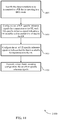
- FIG. 4 illustrates an example of a process 400 that supports a C-DRX wake up procedure in accordance with various aspects of the present disclosure.
- process 400 may implement aspects of wireless communications systems 100 and/or 300 , as well as method 200 .
- process 400 may include a base station 405 and a UE 410 , which may be examples of the corresponding devices described herein.
- the base station 405 may identify that data is available for the UE 410 .
- the UE 410 may be operating in a DRX mode, e.g., a C-DRX mode.
- the DRX mode may include the UE 410 switching or otherwise transitioning between an active state and a sleep state.
- the base station 405 may configure a plurality of UE-specific reference signals (RSs) for the UE 410 .
- the plurality of UE-specific reference signals may carry or otherwise convey an indication of a UE identifier.
- the base station 405 may encode a plurality of CSI-RSs with some or all of the UE identifier.
- the base station 405 may encode the plurality of UE-specific reference signals with some or all of a C-RNTI of the UE 410 .
- the base station 405 may configure a bit in the plurality of UE-specific reference signals to indicate that the data is available for transmission to the UE 410 .
- the plurality of UE-specific reference signals may explicitly use an ON/OFF bit to indicate whether data is available for the UE.
- the base station 405 may transmit (and the UE 410 may receive at least one of) the plurality of UE-specific reference signals to the UE 410 using a beam sweeping configuration.
- the beam sweeping configuration may include the base station 405 transmitting each UE-specific reference signal in a different beamforming direction.
- the UE 410 may identify that data is available for the UE 410 based on receiving at least one of the plurality of UE-specific reference signals.
- the UE 410 may identify that data is available based on receiving one (or more) of the UE-specific reference signals beam swept to the UE 410 .
- the UE 410 may identify the available data by decoding a CSI-RS using at least a portion of the UE identifier, e.g., the UE-specific reference signal may be the CSI-RS. In some aspects, the UE 410 may use the C-RNTI to decode the UE-specific reference signals to identify that data is available. In some aspects, the UE 410 may decode one or more bits in the UE-specific reference signals to identify that data is available.
- the UE 410 may transmit a beam recovery signal to the base station 405 in response to the data being available.
- the beam recovery signal may include an identifier of the transmit beam used by the UE 410 to transmit the beam recovery signal.
- the beam recovery signal may include an identifier of the transmit beam used to transmit the at least one UE-specific reference signal that has the highest receive power, highest receive quality, the lowest interference level, or the like.
- the identifier may include a beam index of the indicated beam.
- the base station 405 may select a transmit beam to use to transmit the data to the UE 410 based on the received beam recovery signal. In some aspects, the base station 405 may identify a beam index for a transmit beam used by the UE 410 to transmit the beam recovery signal.
- the base station 405 may transmit (and the UE 410 may receive) the identified data to the UE 410 using the selected transmit beam.
- FIG. 5 shows a block diagram 500 of a wireless device 505 that supports a C-DRX wake up procedure in accordance with aspects of the present disclosure.
- Wireless device 505 may be an example of aspects of a base station 105 as described herein.
- Wireless device 505 may include receiver 510 , base station communications manager 515 , and transmitter 520 .
- Wireless device 505 may also include a processor. Each of these components may be in communication with one another (e.g., via one or more buses).
- Receiver 510 may receive information such as packets, user data, or control information associated with various information channels (e.g., control channels, data channels, and information related to a C-DRX wake up procedure, etc.). Information may be passed on to other components of the device.
- the receiver 510 may be an example of aspects of the transceiver 835 described with reference to FIG. 8 .
- the receiver 510 may utilize a single antenna or a set of antennas.
- Base station communications manager 515 may be an example of aspects of the base station communications manager 815 described with reference to FIG. 8 .
- Base station communications manager 515 and/or at least some of its various sub-components may be implemented in hardware, software executed by a processor, firmware, or any combination thereof. If implemented in software executed by a processor, the functions of the base station communications manager 515 and/or at least some of its various sub-components may be executed by a general-purpose processor, a digital signal processor (DSP), an application-specific integrated circuit (ASIC), an field-programmable gate array (FPGA) or other programmable logic device, discrete gate or transistor logic, discrete hardware components, or any combination thereof designed to perform the functions described in the present disclosure.
- DSP digital signal processor
- ASIC application-specific integrated circuit
- FPGA field-programmable gate array
- the base station communications manager 515 and/or at least some of its various sub-components may be physically located at various positions, including being distributed such that portions of functions are implemented at different physical locations by one or more physical devices.
- base station communications manager 515 and/or at least some of its various sub-components may be a separate and distinct component in accordance with various aspects of the present disclosure.
- base station communications manager 515 and/or at least some of its various sub-components may be combined with one or more other hardware components, including but not limited to an I/O component, a transceiver, a network server, another computing device, one or more other components described in the present disclosure, or a combination thereof in accordance with various aspects of the present disclosure.
- Base station communications manager 515 may identify that data is available to be transmitted to a UE that is operating in a DRX mode, configure a set of UE-specific reference signals for transmission to the UE, each UE-specific reference signal indicating a UE identifier and an availability of data for the UE, and transmit, using a beam sweeping configuration, the set of UE-specific reference signals.
- Transmitter 520 may transmit signals generated by other components of the device.
- the transmitter 520 may be collocated with a receiver 510 in a transceiver module.
- the transmitter 520 may be an example of aspects of the transceiver 835 described with reference to FIG. 8 .
- the transmitter 520 may utilize a single antenna or a set of antennas.
- FIG. 6 shows a block diagram 600 of a wireless device 605 that supports a C-DRX wake up procedure in accordance with aspects of the present disclosure.
- Wireless device 605 may be an example of aspects of a wireless device 505 or a base station 105 as described with reference to FIG. 5 .
- Wireless device 605 may include receiver 610 , base station communications manager 615 , and transmitter 620 .
- Wireless device 605 may also include a processor. Each of these components may be in communication with one another (e.g., via one or more buses).
- Receiver 610 may receive information such as packets, user data, or control information associated with various information channels (e.g., control channels, data channels, and information related to a C-DRX wake up procedure, etc.). Information may be passed on to other components of the device.
- the receiver 610 may be an example of aspects of the transceiver 835 described with reference to FIG. 8 .
- the receiver 610 may utilize a single antenna or a set of antennas.
- Base station communications manager 615 may be an example of aspects of the base station communications manager 815 described with reference to FIG. 8 .
- Base station communications manager 615 may also include data manager 625 , UE-RS manager 630 , and beam manager 635 .
- Data manager 625 may identify that data is available to be transmitted to a UE that is operating in a DRX mode.
- UE-RS manager 630 may configure a set of UE-specific reference signals for transmission to the UE, each UE-specific reference signal indicating a UE identifier and an availability of data for the UE.
- configuring the set of UE-specific reference signals for transmission to the UE includes: encoding a set of CSI-RSs with at least a portion of the UE identifier.
- configuring the set of UE-specific reference signals for transmission to the UE includes: encoding the set of UE-specific reference signals with at least a portion of a C-RNTI for the UE.
- transmitting the plurality of UE-specific reference signals conveys the indication of availability of data for the UE.
- Beam manager 635 may transmit, using a beam sweeping configuration, the set of UE-specific reference signals and receive a beam recovery signal from the UE in response to the set of UE-specific reference signals.
- the beam sweeping configuration includes transmitting each UE-specific reference signal in a different beamforming direction.
- Transmitter 620 may transmit signals generated by other components of the device.
- the transmitter 620 may be collocated with a receiver 610 in a transceiver module.
- the transmitter 620 may be an example of aspects of the transceiver 835 described with reference to FIG. 8 .
- the transmitter 620 may utilize a single antenna or a set of antennas.
- FIG. 7 shows a block diagram 700 of a base station communications manager 715 that supports a C-DRX wake up procedure in accordance with aspects of the present disclosure.
- the base station communications manager 715 may be an example of aspects of a base station communications manager 515 , a base station communications manager 615 , or a base station communications manager 815 described with reference to FIGS. 5, 6, and 8 .
- the base station communications manager 715 may include data manager 720 , UE-RS manager 725 , beam manager 730 , UE-RS configuration manager 735 , and beam recovery manager 740 . Each of these modules may communicate, directly or indirectly, with one another (e.g., via one or more buses).
- Data manager 720 may identify that data is available to be transmitted to a UE that is operating in a DRX mode.
- UE-RS manager 725 may configure a set of UE-specific reference signals for transmission to the UE, each UE-specific reference signal indicating a UE identifier and an availability of data for the UE.
- configuring the set of UE-specific reference signals for transmission to the UE includes: encoding a set of CSI-RSs with at least a portion of the UE identifier.
- configuring the set of UE-specific reference signals for transmission to the UE includes: encoding the set of UE-specific reference signals with at least a portion of a C-RNTI for the UE.
- transmitting the plurality of UE-specific reference signals conveys the indication of availability of data for the UE.
- Beam manager 730 may transmit, using a beam sweeping configuration, the set of UE-specific reference signals and receive a beam recovery signal from the UE in response to the set of UE-specific reference signals.
- the beam sweeping configuration includes transmitting each UE-specific reference signal in a different beamforming direction.
- UE-RS configuration manager 735 may configure a bit in the set of UE-specific reference signals to indicate that the data is available for transmission to the UE.
- Beam recovery manager 740 may receive a beam recovery signal from the UE in response to the set of UE-specific reference signals, select a transmit beam to use to transmit the data to the UE based on the received beam recovery signal, identify a beam index for a transmit beam used by the UE to transmit the beam recovery signal, and transmit the data to the UE based on the identified beam index.
- FIG. 8 shows a diagram of a system 800 including a device 805 that supports a C-DRX wake up procedure in accordance with aspects of the present disclosure.
- Device 805 may be an example of or include the components of wireless device 505 , wireless device 605 , or a base station 105 as described above, e.g., with reference to FIGS. 5 and 6 .
- Device 805 may include components for bi-directional voice and data communications including components for transmitting and receiving communications, including base station communications manager 815 , processor 820 , memory 825 , software 830 , transceiver 835 , antenna 840 , network communications manager 845 , and inter-station communications manager 850 . These components may be in electronic communication via one or more buses (e.g., bus 810 ).
- Device 805 may communicate wirelessly with one or more UEs 115 .
- Processor 820 may include an intelligent hardware device, (e.g., a general-purpose processor, a DSP, a central processing unit (CPU), a microcontroller, an ASIC, an FPGA, a programmable logic device, a discrete gate or transistor logic component, a discrete hardware component, or any combination thereof).
- processor 820 may be configured to operate a memory array using a memory controller.
- a memory controller may be integrated into processor 820 .
- Processor 820 may be configured to execute computer-readable instructions stored in a memory to perform various functions (e.g., functions or tasks supporting a C-DRX wake up procedure).
- Memory 825 may include random access memory (RAM) and read only memory (ROM).
- the memory 825 may store computer-readable, computer-executable software 830 including instructions that, when executed, cause the processor to perform various functions described herein.
- the memory 825 may contain, among other things, a basic input/output system (BIOS) which may control basic hardware or software operation such as the interaction with peripheral components or devices.
- BIOS basic input/output system
- Software 830 may include code to implement aspects of the present disclosure, including code to support a C-DRX wake up procedure.
- Software 830 may be stored in a non-transitory computer-readable medium such as system memory or other memory. In some cases, the software 830 may not be directly executable by the processor but may cause a computer (e.g., when compiled and executed) to perform functions described herein.
- Transceiver 835 may communicate bi-directionally, via one or more antennas, wired, or wireless links as described above.
- the transceiver 835 may represent a wireless transceiver and may communicate bi-directionally with another wireless transceiver.
- the transceiver 835 may also include a modem to modulate the packets and provide the modulated packets to the antennas for transmission, and to demodulate packets received from the antennas.
- the wireless device may include a single antenna 840 .
- the device may have more than one antenna 840 , which may be capable of concurrently transmitting or receiving multiple wireless transmissions.
- Network communications manager 845 may manage communications with the core network (e.g., via one or more wired backhaul links). For example, the network communications manager 845 may manage the transfer of data communications for client devices, such as one or more UEs 115 .
- Inter-station communications manager 850 may manage communications with other base station 105 , and may include a controller or scheduler for controlling communications with UEs 115 in cooperation with other base stations 105 .
- the inter-station communications manager 850 may coordinate scheduling for transmissions to UEs 115 for various interference mitigation techniques such as beamforming or joint transmission.
- inter-station communications manager 850 may provide an X2 interface within an Long Term Evolution (LTE)/LTE-A wireless communication network technology to provide communication between base stations 105 .
- LTE Long Term Evolution
- LTE-A wireless communication network technology to provide communication between base stations 105 .
- FIG. 9 shows a block diagram 900 of a wireless device 905 that supports a C-DRX wake up procedure in accordance with aspects of the present disclosure.
- Wireless device 905 may be an example of aspects of a UE 115 as described herein.
- Wireless device 905 may include receiver 910 , UE communications manager 915 , and transmitter 920 .
- Wireless device 905 may also include a processor. Each of these components may be in communication with one another (e.g., via one or more buses).
- Receiver 910 may receive information such as packets, user data, or control information associated with various information channels (e.g., control channels, data channels, and information related to a C-DRX wake up procedure, etc.). Information may be passed on to other components of the device.
- the receiver 910 may be an example of aspects of the transceiver 1235 described with reference to FIG. 12 .
- the receiver 910 may utilize a single antenna or a set of antennas.
- UE communications manager 915 may be an example of aspects of the UE communications manager 1215 described with reference to FIG. 12 .
- UE communications manager 915 and/or at least some of its various sub-components may be implemented in hardware, software executed by a processor, firmware, or any combination thereof. If implemented in software executed by a processor, the functions of the UE communications manager 915 and/or at least some of its various sub-components may be executed by a general-purpose processor, a DSP, an ASIC, an FPGA or other programmable logic device, discrete gate or transistor logic, discrete hardware components, or any combination thereof designed to perform the functions described in the present disclosure.
- the UE communications manager 915 and/or at least some of its various sub-components may be physically located at various positions, including being distributed such that portions of functions are implemented at different physical locations by one or more physical devices.
- UE communications manager 915 and/or at least some of its various sub-components may be a separate and distinct component in accordance with various aspects of the present disclosure. In other examples, UE communications manager 915 and/or at least some of its various sub-components may be combined with one or more other hardware components, including but not limited to an I/O component, a transceiver, a network server, another computing device, one or more other components described in the present disclosure, or a combination thereof in accordance with various aspects of the present disclosure.
- UE communications manager 915 may receive, while operating in a DRX mode, a UE-specific reference signal from a base station, identify, based on the received UE-specific reference signal, that data for the UE is available from the base station, and transmit, based on the identification, a signal to the base station, the signal including a beam index.
- Transmitter 920 may transmit signals generated by other components of the device.
- the transmitter 920 may be collocated with a receiver 910 in a transceiver module.
- the transmitter 920 may be an example of aspects of the transceiver 1235 described with reference to FIG. 12 .
- the transmitter 920 may utilize a single antenna or a set of antennas.
- FIG. 10 shows a block diagram 1000 of a wireless device 1005 that supports a C-DRX wake up procedure in accordance with aspects of the present disclosure.
- Wireless device 1005 may be an example of aspects of a wireless device 905 or a UE 115 as described with reference to FIG. 9 .
- Wireless device 1005 may include receiver 1010 , UE communications manager 1015 , and transmitter 1020 .
- Wireless device 1005 may also include a processor. Each of these components may be in communication with one another (e.g., via one or more buses).
- Receiver 1010 may receive information such as packets, user data, or control information associated with various information channels (e.g., control channels, data channels, and information related to a C-DRX wake up procedure, etc.). Information may be passed on to other components of the device.
- the receiver 1010 may be an example of aspects of the transceiver 1235 described with reference to FIG. 12 .
- the receiver 1010 may utilize a single antenna or a set of antennas.
- UE communications manager 1015 may be an example of aspects of the UE communications manager 1215 described with reference to FIG. 12 .
- UE communications manager 1015 may also include UE-RS manager 1025 , data manager 1030 , and beam recovery manager 1035 .
- UE-RS manager 1025 may receive, while operating in a DRX mode, a UE-specific reference signal from a base station.
- Data manager 1030 may identify, based on the received UE-specific reference signal, that data for the UE is available from the base station, receive at least a portion of the data from the base station in response to the transmitted beam recovery signal, and decode at least one bit of the UE-specific reference signal to identify that the data is available for the UE.
- identifying that the data for the UE is available includes: decoding a channel state information reference signal (CSI-RS) using at least a portion of an identifier of the UE, where the received UE-specific reference signal includes the CSI-RS.
- identifying that the data for the UE is available includes: decoding the UE-specific reference signal using a cell radio network temporary identifier (C-RNTI) for the UE.
- transmitting the plurality of UE-specific reference signals conveys the indication of availability of data for the UE.
- Beam recovery manager 1035 may transmit, based on the identification, a signal to the base station, the signal including a beam index.
- Transmitter 1020 may transmit signals generated by other components of the device.
- the transmitter 1020 may be collocated with a receiver 1010 in a transceiver module.
- the transmitter 1020 may be an example of aspects of the transceiver 1235 described with reference to FIG. 12 .
- the transmitter 1020 may utilize a single antenna or a set of antennas.
- FIG. 11 shows a block diagram 1100 of a UE communications manager 1115 that supports a C-DRX wake up procedure in accordance with aspects of the present disclosure.
- the UE communications manager 1115 may be an example of aspects of a UE communications manager 1215 described with reference to FIGS. 9, 10, and 12 .
- the UE communications manager 1115 may include UE-RS manager 1120 , data manager 1125 , and beam recovery manager 1130 . Each of these modules may communicate, directly or indirectly, with one another (e.g., via one or more buses).
- UE-RS manager 1120 may receive, while operating in a DRX mode, a UE-specific reference signal from a base station.
- Data manager 1125 may identify, based on the received UE-specific reference signal, that data for the UE is available from the base station, receive at least a portion of the data from the base station in response to the transmitted beam recovery signal, and decode at least one bit of the UE-specific reference signal to identify that the data is available for the UE.
- identifying that the data for the UE is available includes: decoding a channel state information reference signal (CSI-RS) using at least a portion of an identifier of the UE, where the received UE-specific reference signal includes the CSI-RS.
- identifying that the data for the UE is available includes: decoding the UE-specific reference signal using a cell radio network temporary identifier (C-RNTI) for the UE.
- transmitting the plurality of UE-specific reference signals conveys the indication of availability of data for the UE.
- Beam recovery manager 1130 may transmit, based on the identification, a signal to the base station, the signal including a beam index.
- the signal is a beam recovery signal.
- FIG. 12 shows a diagram of a system 1200 including a device 1205 that supports a C-DRX wake up procedure in accordance with aspects of the present disclosure.
- Device 1205 may be an example of or include the components of UE 115 as described above, e.g., with reference to FIG. 1 .
- Device 1205 may include components for bi-directional voice and data communications including components for transmitting and receiving communications, including UE communications manager 1215 , processor 1220 , memory 1225 , software 1230 , transceiver 1235 , antenna 1240 , and I/O controller 1245 . These components may be in electronic communication via one or more buses (e.g., bus 1210 ).
- Device 1205 may communicate wirelessly with one or more base stations 105 .
- Processor 1220 may include an intelligent hardware device, (e.g., a general-purpose processor, a DSP, a CPU, a microcontroller, an ASIC, an FPGA, a programmable logic device, a discrete gate or transistor logic component, a discrete hardware component, or any combination thereof).
- processor 1220 may be configured to operate a memory array using a memory controller.
- a memory controller may be integrated into processor 1220 .
- Processor 1220 may be configured to execute computer-readable instructions stored in a memory to perform various functions (e.g., functions or tasks supporting a C-DRX wake up procedure).
- Memory 1225 may include RAM and ROM.
- the memory 1225 may store computer-readable, computer-executable software 1230 including instructions that, when executed, cause the processor to perform various functions described herein.
- the memory 1225 may contain, among other things, a BIOS which may control basic hardware or software operation such as the interaction with peripheral components or devices.
- Software 1230 may include code to implement aspects of the present disclosure, including code to support a C-DRX wake up procedure.
- Software 1230 may be stored in a non-transitory computer-readable medium such as system memory or other memory. In some cases, the software 1230 may not be directly executable by the processor but may cause a computer (e.g., when compiled and executed) to perform functions described herein.
- Transceiver 1235 may communicate bi-directionally, via one or more antennas, wired, or wireless links as described above.
- the transceiver 1235 may represent a wireless transceiver and may communicate bi-directionally with another wireless transceiver.
- the transceiver 1235 may also include a modem to modulate the packets and provide the modulated packets to the antennas for transmission, and to demodulate packets received from the antennas.
- the wireless device may include a single antenna 1240 .
- the device may have more than one antenna 1240 , which may be capable of concurrently transmitting or receiving multiple wireless transmissions.
- I/O controller 1245 may manage input and output signals for device 1205 . I/O controller 1245 may also manage peripherals not integrated into device 1205 . In some cases, I/O controller 1245 may represent a physical connection or port to an external peripheral. In some cases, I/O controller 1245 may utilize an operating system such as iOS®, ANDROID®, MS-DOS®, MS-WINDOWS®, OS/2®, UNIX®, LINUX®, or another known operating system. In other cases, I/O controller 1245 may represent or interact with a modem, a keyboard, a mouse, a touchscreen, or a similar device. In some cases, I/O controller 1245 may be implemented as part of a processor. In some cases, a user may interact with device 1205 via I/O controller 1245 or via hardware components controlled by I/O controller 1245 .
- I/O controller 1245 may manage input and output signals for device 1205 . I/O controller 1245 may also manage peripherals not integrated into device 1205 . In some cases, I
- FIG. 13 shows a flowchart illustrating a method 1300 for a C-DRX wake up procedure in accordance with aspects of the present disclosure.
- the operations of method 1300 may be implemented by a base station 105 or its components as described herein.
- the operations of method 1300 may be performed by a base station communications manager as described with reference to FIGS. 5 through 8 .
- a base station 105 may execute a set of codes to control the functional elements of the device to perform the functions described below. Additionally or alternatively, the base station 105 may perform aspects of the functions described below using special-purpose hardware.
- the base station 105 may identify that data is available to be transmitted to a UE that is operating in a DRX mode.
- the operations of block 1305 may be performed according to the methods described herein. In certain examples, aspects of the operations of block 1305 may be performed by a data manager as described with reference to FIGS. 5 through 8 .
- the base station 105 may configure a plurality of UE-specific reference signals for transmission to the UE, each UE-specific reference signal indicating a UE identifier and an availability of data for the UE.
- the operations of block 1310 may be performed according to the methods described herein. In certain examples, aspects of the operations of block 1310 may be performed by a UE-RS manager as described with reference to FIGS. 5 through 8 .
- the base station 105 may transmit, using a beam sweeping configuration, the plurality of UE-specific reference signals.
- the operations of block 1315 may be performed according to the methods described herein. In certain examples, aspects of the operations of block 1315 may be performed by a beam manager as described with reference to FIGS. 5 through 8 .
- FIG. 14 shows a flowchart illustrating a method 1400 for a C-DRX wake up procedure in accordance with aspects of the present disclosure.
- the operations of method 1400 may be implemented by a base station 105 or its components as described herein.
- the operations of method 1400 may be performed by a base station communications manager as described with reference to FIGS. 5 through 8 .
- a base station 105 may execute a set of codes to control the functional elements of the device to perform the functions described below. Additionally or alternatively, the base station 105 may perform aspects of the functions described below using special-purpose hardware.
- the base station 105 may identify that data is available to be transmitted to a UE that is operating in a DRX mode.
- the operations of block 1405 may be performed according to the methods described herein. In certain examples, aspects of the operations of block 1405 may be performed by a data manager as described with reference to FIGS. 5 through 8 .
- the base station 105 may configure a plurality of UE-specific reference signals for transmission to the UE, each UE-specific reference signal indicating a UE identifier and an availability of data for the UE.
- the operations of block 1410 may be performed according to the methods described herein. In certain examples, aspects of the operations of block 1410 may be performed by a UE-RS manager as described with reference to FIGS. 5 through 8 .
- the base station 105 may configure a bit in the plurality of UE-specific reference signals to indicate that the data is available for transmission to the UE.
- the operations of block 1415 may be performed according to the methods described herein. In certain examples, aspects of the operations of block 1415 may be performed by a UE-RS configuration manager as described with reference to FIGS. 5 through 8 .
- the base station 105 may transmit, using a beam sweeping configuration, the plurality of UE-specific reference signals.
- the operations of block 1420 may be performed according to the methods described herein. In certain examples, aspects of the operations of block 1420 may be performed by a beam manager as described with reference to FIGS. 5 through 8 .
- FIG. 15 shows a flowchart illustrating a method 1500 for a C-DRX wake up procedure in accordance with aspects of the present disclosure.
- the operations of method 1500 may be implemented by a UE 115 or its components as described herein.
- the operations of method 1500 may be performed by a UE communications manager as described with reference to FIGS. 9 through 12 .
- a UE 115 may execute a set of codes to control the functional elements of the device to perform the functions described below. Additionally or alternatively, the UE 115 may perform aspects of the functions described below using special-purpose hardware.
- the UE 115 may receive, while operating in a DRX mode, a UE-specific reference signal from a base station.
- the operations of block 1505 may be performed according to the methods described herein. In certain examples, aspects of the operations of block 1505 may be performed by a UE-RS manager as described with reference to FIGS. 9 through 12 .
- the UE 115 may identify, based at least in part on the received UE-specific reference signal, that data for the UE is available from the base station.
- the operations of block 1510 may be performed according to the methods described herein. In certain examples, aspects of the operations of block 1510 may be performed by a data manager as described with reference to FIGS. 9 through 12 .
- the UE 115 may transmit, based at least in part on the identification, a signal to the base station, the signal including a beam index.
- the operations of block 1515 may be performed according to the methods described herein. In certain examples, aspects of the operations of block 1515 may be performed by a beam recovery manager as described with reference to FIGS. 9 through 12 .
- FIG. 16 shows a flowchart illustrating a method 1600 for a C-DRX wake up procedure in accordance with aspects of the present disclosure.
- the operations of method 1600 may be implemented by a UE 115 or its components as described herein.
- the operations of method 1600 may be performed by a UE communications manager as described with reference to FIGS. 9 through 12 .
- a UE 115 may execute a set of codes to control the functional elements of the device to perform the functions described below. Additionally or alternatively, the UE 115 may perform aspects of the functions described below using special-purpose hardware.
- the UE 115 may receive, while operating in DRX mode, a UE-specific reference signal from a base station.
- the operations of block 1605 may be performed according to the methods described herein. In certain examples, aspects of the operations of block 1605 may be performed by a UE-RS manager as described with reference to FIGS. 9 through 12 .
- the UE 115 may identify, based at least in part on the received UE-specific reference signal, that data for the UE is available from the base station.
- the operations of block 1610 may be performed according to the methods described herein. In certain examples, aspects of the operations of block 1610 may be performed by a data manager as described with reference to FIGS. 9 through 12 .
- the UE 115 may transmit, based at least in part on the identification, a signal to the base station, the signal including a beam index.
- the operations of block 1615 may be performed according to the methods described herein. In certain examples, aspects of the operations of block 1615 may be performed by a beam recovery manager as described with reference to FIGS. 9 through 12 .
- the UE 115 may receive at least a portion of the data from the base station in response to the transmitted beam recovery signal.
- the operations of block 1620 may be performed according to the methods described herein. In certain examples, aspects of the operations of block 1620 may be performed by a data manager as described with reference to FIGS. 9 through 12 .
- CDMA code division multiple access
- TDMA time division multiple access
- FDMA frequency division multiple access
- OFDMA orthogonal frequency division multiple access
- SC-FDMA single carrier frequency division multiple access
- a CDMA system may implement a radio technology such as CDMA2000, Universal Terrestrial Radio Access (UTRA), etc.
- CDMA2000 covers IS-2000, IS-95, and IS-856 standards.
- IS-2000 Releases may be commonly referred to as CDMA2000 1 ⁇ , 1 ⁇ , etc.
- IS-856 TIA-856) is commonly referred to as CDMA2000 1 ⁇ EV-DO, High Rate Packet Data (HRPD), etc.
- UTRA includes Wideband CDMA (WCDMA) and other variants of CDMA.
- a TDMA system may implement a radio technology such as Global System for Mobile Communications (GSM).
- GSM Global System for Mobile Communications
- An OFDMA system may implement a radio technology such as Ultra Mobile Broadband (UMB), Evolved UTRA (E-UTRA), Institute of Electrical and Electronics Engineers (IEEE) 802.11 (Wi-Fi), IEEE 802.16 (WiMAX), IEEE 802.20, Flash-OFDM, etc.
- UMB Ultra Mobile Broadband
- E-UTRA Evolved UTRA
- IEEE Institute of Electrical and Electronics Engineers
- Wi-Fi Wi-Fi
- WiMAX IEEE 802.16
- IEEE 802.20 Flash-OFDM
- UMB Ultra Mobile Broadband
- E-UTRA Evolved UTRA
- IEEE 802.11 Wi-Fi
- WiMAX IEEE 802.16
- Flash-OFDM Flash-OFDM
- UTRA and E-UTRA are part of Universal Mobile Telecommunications System (UMTS).
- LTE and LTE-A are releases of UMTS that use E-UTRA.
- LTE or NR may be described for purposes of example, and LTE or NR terminology may be used in much of the description, the techniques described herein are applicable beyond LTE or NR applications.
- a macro cell generally covers a relatively large geographic area (e.g., several kilometers in radius) and may allow unrestricted access by UEs 115 with service subscriptions with the network provider.
- a small cell may be associated with a lower-powered base station 105 , as compared with a macro cell, and a small cell may operate in the same or different (e.g., licensed, unlicensed, etc.) frequency bands as macro cells.
- Small cells may include pico cells, femto cells, and micro cells according to various examples.
- a pico cell for example, may cover a small geographic area and may allow unrestricted access by UEs 115 with service subscriptions with the network provider.
- a femto cell may also cover a small geographic area (e.g., a home) and may provide restricted access by UEs 115 having an association with the femto cell (e.g., UEs 115 in a closed subscriber group (CSG), UEs 115 for users in the home, and the like).
- An eNB for a macro cell may be referred to as a macro eNB.
- An eNB for a small cell may be referred to as a small cell eNB, a pico eNB, a femto eNB, or a home eNB.
- An eNB may support one or multiple (e.g., two, three, four, and the like) cells, and may also support communications using one or multiple component carriers.
- the wireless communications system 100 or systems described herein may support synchronous or asynchronous operation.
- the base stations 105 may have similar frame timing, and transmissions from different base stations 105 may be approximately aligned in time.
- the base stations 105 may have different frame timing, and transmissions from different base stations 105 may not be aligned in time.
- the techniques described herein may be used for either synchronous or asynchronous operations.
- Information and signals described herein may be represented using any of a variety of different technologies and techniques.
- data, instructions, commands, information, signals, bits, symbols, and chips that may be referenced throughout the above description may be represented by voltages, currents, electromagnetic waves, magnetic fields or particles, optical fields or particles, or any combination thereof.
- DSP digital signal processor
- ASIC application-specific integrated circuit
- FPGA field-programmable gate array
- PLD programmable logic device
- a general-purpose processor may be a microprocessor, but in the alternative, the processor may be any conventional processor, controller, microcontroller, or state machine.
- a processor may also be implemented as a combination of computing devices (e.g., a combination of a DSP and a microprocessor, multiple microprocessors, one or more microprocessors in conjunction with a DSP core, or any other such configuration).
- the functions described herein may be implemented in hardware, software executed by a processor, firmware, or any combination thereof. If implemented in software executed by a processor, the functions may be stored on or transmitted over as one or more instructions or code on a computer-readable medium. Other examples and implementations are within the scope of the disclosure and appended claims. For example, due to the nature of software, functions described above can be implemented using software executed by a processor, hardware, firmware, hardwiring, or combinations of any of these. Features implementing functions may also be physically located at various positions, including being distributed such that portions of functions are implemented at different physical locations.
- Computer-readable media includes both non-transitory computer storage media and communication media including any medium that facilitates transfer of a computer program from one place to another.
- a non-transitory storage medium may be any available medium that can be accessed by a general purpose or special purpose computer.
- non-transitory computer-readable media may comprise random-access memory (RAM), read-only memory (ROM), electrically erasable programmable read only memory (EEPROM), flash memory, compact disk (CD) ROM or other optical disk storage, magnetic disk storage or other magnetic storage devices, or any other non-transitory medium that can be used to carry or store desired program code means in the form of instructions or data structures and that can be accessed by a general-purpose or special-purpose computer, or a general-purpose or special-purpose processor.
- RAM random-access memory
- ROM read-only memory
- EEPROM electrically erasable programmable read only memory
- CD compact disk
- magnetic disk storage or other magnetic storage devices or any other non-transitory medium that can be used to carry
- any connection is properly termed a computer-readable medium.
- the software is transmitted from a website, server, or other remote source using a coaxial cable, fiber optic cable, twisted pair, digital subscriber line (DSL), or wireless technologies such as infrared, radio, and microwave
- the coaxial cable, fiber optic cable, twisted pair, DSL, or wireless technologies such as infrared, radio, and microwave are included in the definition of medium.
- Disk and disc include CD, laser disc, optical disc, digital versatile disc (DVD), floppy disk and Blu-ray disc where disks usually reproduce data magnetically, while discs reproduce data optically with lasers. Combinations of the above are also included within the scope of computer-readable media.
- “or” as used in a list of items indicates an inclusive list such that, for example, a list of at least one of A, B, or C means A or B or C or AB or AC or BC or ABC (i.e., A and B and C).
- the phrase “based on” shall not be construed as a reference to a closed set of conditions. For example, an exemplary step that is described as “based on condition A” may be based on both a condition A and a condition B without departing from the scope of the present disclosure.
- the phrase “based on” shall be construed in the same manner as the phrase “based at least in part on.”
Abstract
Description
Claims (26)
Priority Applications (4)
| Application Number | Priority Date | Filing Date | Title |
|---|---|---|---|
| US16/032,742 US11184848B2 (en) | 2017-08-11 | 2018-07-11 | Connected discontinuous reception wake up procedure |
| PCT/US2018/042320 WO2019032248A1 (en) | 2017-08-11 | 2018-07-16 | Connected discontinuous reception wake up procedure |
| EP18750293.5A EP3665960B1 (en) | 2017-08-11 | 2018-07-16 | Connected discontinuous reception wake up procedure |
| CN201880051151.6A CN110999411B (en) | 2017-08-11 | 2018-07-16 | Connected discontinuous reception wakeup procedure |
Applications Claiming Priority (2)
| Application Number | Priority Date | Filing Date | Title |
|---|---|---|---|
| US201762544739P | 2017-08-11 | 2017-08-11 | |
| US16/032,742 US11184848B2 (en) | 2017-08-11 | 2018-07-11 | Connected discontinuous reception wake up procedure |
Publications (2)
| Publication Number | Publication Date |
|---|---|
| US20190053153A1 US20190053153A1 (en) | 2019-02-14 |
| US11184848B2 true US11184848B2 (en) | 2021-11-23 |
Family
ID=65271757
Family Applications (1)
| Application Number | Title | Priority Date | Filing Date |
|---|---|---|---|
| US16/032,742 Active 2038-07-24 US11184848B2 (en) | 2017-08-11 | 2018-07-11 | Connected discontinuous reception wake up procedure |
Country Status (4)
| Country | Link |
|---|---|
| US (1) | US11184848B2 (en) |
| EP (1) | EP3665960B1 (en) |
| CN (1) | CN110999411B (en) |
| WO (1) | WO2019032248A1 (en) |
Cited By (2)
| Publication number | Priority date | Publication date | Assignee | Title |
|---|---|---|---|---|
| US20220303914A1 (en) * | 2021-03-17 | 2022-09-22 | T-Mobile Usa, Inc. | Dynamic switching of user equipment power class |
| US11729856B2 (en) | 2017-08-11 | 2023-08-15 | Qualcomm Incorporated | Beam management for beam-swept wakeup signals |
Families Citing this family (3)
| Publication number | Priority date | Publication date | Assignee | Title |
|---|---|---|---|---|
| US10736082B2 (en) | 2016-10-31 | 2020-08-04 | Qualcomm Incorporated | Transmission of a common control in a beamforming system |
| WO2020173915A1 (en) * | 2019-02-25 | 2020-09-03 | Nokia Technologies Oy | Method for beam failure detection |
| US11510276B2 (en) * | 2019-07-01 | 2022-11-22 | Apple Inc. | Low latency beam alignment |
Citations (31)
| Publication number | Priority date | Publication date | Assignee | Title |
|---|---|---|---|---|
| US20100238824A1 (en) * | 2009-03-20 | 2010-09-23 | Qualcomm Incorporated | Feedback mechanisms for beamforming operation |
| US20110243261A1 (en) * | 2010-03-30 | 2011-10-06 | Infineon Technologies Ag | Communication device |
| US20120275366A1 (en) * | 2011-04-29 | 2012-11-01 | Nicholas William Anderson | Switching activation of ue receviers |
| US20140036747A1 (en) * | 2012-08-03 | 2014-02-06 | Motorola Mobility Llc | Method and Apparatus For Receiving A Control Channel |
| US20150003311A1 (en) * | 2012-01-26 | 2015-01-01 | Panasonic Intellectual Property Corporation Of America | Discontinuous reception operation with additional wake-up opportunities |
| US20170127325A1 (en) * | 2015-11-02 | 2017-05-04 | Telefonaktiebolaget L M Ericsson (Publ) | Method and apparatus for controlling selection of the solution for wlan and unlicensed spectrum usage |
| US20170181219A1 (en) | 2015-12-16 | 2017-06-22 | Intel IP Corporation | Method for power management and power management controller for a radio receiver |
| US20170251518A1 (en) * | 2016-02-26 | 2017-08-31 | Samsung Electronics Co., Ltd. | System and method of connected mode discontinuous operation in beamformed system |
| WO2017167755A1 (en) | 2016-04-01 | 2017-10-05 | Telefonaktiebolaget Lm Ericsson (Publ) | Wireless communications |
| US20170311342A1 (en) * | 2016-04-22 | 2017-10-26 | Lg Electronics Inc. | Method and base station for receiving system information, and method and user equipment for transmitting system information |
| US20170325167A1 (en) * | 2014-12-02 | 2017-11-09 | Telefonaktiebolaget Lm Ericsson (Publ) | Wake-Up for D2D Communication |
| WO2017197642A1 (en) | 2016-05-20 | 2017-11-23 | Nokia Technologies Oy | Dynamic csi-rs sharing scheme |
| US20170339675A1 (en) * | 2016-05-18 | 2017-11-23 | Futurewei Technologies, Inc. | Method of Operating a Cellular Network including High Frequency Burst Transmission |
| US20180092129A1 (en) * | 2016-09-23 | 2018-03-29 | Samsung Electronics Co., Ltd. | Method and apparatus for random access in wireless systems |
| US20180092073A1 (en) | 2016-09-28 | 2018-03-29 | Sharp Laboratories Of America, Inc. | User equipments, base stations and methods |
| US20180097598A1 (en) | 2016-09-30 | 2018-04-05 | Qualcomm Incorporated | Use of reference signals to improve user equipment (ue) warm-up before transitioning from an off duration of the ue to an on duration of the ue with respect to a radio frequency spectrum band |
| US20180167883A1 (en) * | 2016-12-13 | 2018-06-14 | Asustek Computer Inc. | Method and apparatus for beam management in a wireless communication system |
| US20180227898A1 (en) * | 2017-02-06 | 2018-08-09 | Samsung Electronics Co., Ltd. | Method and apparatus for beam searching and management in wireless communication system |
| US20180227094A1 (en) * | 2017-02-03 | 2018-08-09 | Futurewei Technologies, Inc. | UE-Assisted SRS Resource Allocation |
| US20180270894A1 (en) * | 2017-03-17 | 2018-09-20 | Ofinno Technologies, Llc | Inactive State Data Forwarding |
| US20180288746A1 (en) * | 2017-04-03 | 2018-10-04 | Huawei Technologies Co., Ltd. | Methods and Systems for Resource Configuration of Wireless Communication Systems |
| US20190013842A1 (en) * | 2016-01-26 | 2019-01-10 | Intel IP Corporation | System and method for system information transmission in stand-alone mmwave systems |
| US20190037498A1 (en) * | 2017-07-25 | 2019-01-31 | Fg Innovation Ip Company Limited | Method and apparatus of power saving for discontinuous reception |
| US20190052334A1 (en) * | 2017-08-10 | 2019-02-14 | Hyoungsuk Jeon | Beam Refinement During RACH |
| US20190059129A1 (en) * | 2017-08-21 | 2019-02-21 | Qualcomm Incorporated | Beam management for connected discontinuous reception with advanced grant indicator |
| US20190058518A1 (en) * | 2016-03-24 | 2019-02-21 | Nokia Solutions And Networks Oy | Beam based communication device and access point |
| US20190059096A1 (en) * | 2017-03-24 | 2019-02-21 | Telefonaktiebolaget Lm Ericsson (Publ) | Extended Scheduling Request (SR) for Enhanced Scheduling Information Indication |
| US20190149306A1 (en) * | 2016-04-01 | 2019-05-16 | Telefonaktiebolaget Lm Ericsson (Publ) | System and Method for Flexible Channel State Information-Reference Signal Transmission |
| US20190182784A1 (en) * | 2016-08-04 | 2019-06-13 | Ntt Docomo, Inc. | User terminal and radio communication method |
| US20190223094A1 (en) * | 2016-07-22 | 2019-07-18 | Samsung Electronics Co., Ltd. | Method and system for system information acquisition in wireless communication system |
| US20190239189A1 (en) * | 2017-03-24 | 2019-08-01 | Lg Electronics Inc. | Method and wireless device for receiving paging message |
Family Cites Families (3)
| Publication number | Priority date | Publication date | Assignee | Title |
|---|---|---|---|---|
| CN107534540B (en) * | 2015-04-10 | 2020-10-23 | Lg 电子株式会社 | Method for reporting channel state information in wireless communication system and apparatus therefor |
| WO2017022870A1 (en) * | 2015-08-03 | 2017-02-09 | Samsung Electronics Co., Ltd. | Method and apparatus for initial access in wireless communication system |
| US10374839B2 (en) * | 2015-08-13 | 2019-08-06 | Lg Electronics Inc. | Operation method of user equipment in relation to CSI-RS in wireless communication system and apparatus supporting the same |
-
2018
- 2018-07-11 US US16/032,742 patent/US11184848B2/en active Active
- 2018-07-16 WO PCT/US2018/042320 patent/WO2019032248A1/en unknown
- 2018-07-16 EP EP18750293.5A patent/EP3665960B1/en active Active
- 2018-07-16 CN CN201880051151.6A patent/CN110999411B/en active Active
Patent Citations (31)
| Publication number | Priority date | Publication date | Assignee | Title |
|---|---|---|---|---|
| US20100238824A1 (en) * | 2009-03-20 | 2010-09-23 | Qualcomm Incorporated | Feedback mechanisms for beamforming operation |
| US20110243261A1 (en) * | 2010-03-30 | 2011-10-06 | Infineon Technologies Ag | Communication device |
| US20120275366A1 (en) * | 2011-04-29 | 2012-11-01 | Nicholas William Anderson | Switching activation of ue receviers |
| US20150003311A1 (en) * | 2012-01-26 | 2015-01-01 | Panasonic Intellectual Property Corporation Of America | Discontinuous reception operation with additional wake-up opportunities |
| US20140036747A1 (en) * | 2012-08-03 | 2014-02-06 | Motorola Mobility Llc | Method and Apparatus For Receiving A Control Channel |
| US20170325167A1 (en) * | 2014-12-02 | 2017-11-09 | Telefonaktiebolaget Lm Ericsson (Publ) | Wake-Up for D2D Communication |
| US20170127325A1 (en) * | 2015-11-02 | 2017-05-04 | Telefonaktiebolaget L M Ericsson (Publ) | Method and apparatus for controlling selection of the solution for wlan and unlicensed spectrum usage |
| US20170181219A1 (en) | 2015-12-16 | 2017-06-22 | Intel IP Corporation | Method for power management and power management controller for a radio receiver |
| US20190013842A1 (en) * | 2016-01-26 | 2019-01-10 | Intel IP Corporation | System and method for system information transmission in stand-alone mmwave systems |
| US20170251518A1 (en) * | 2016-02-26 | 2017-08-31 | Samsung Electronics Co., Ltd. | System and method of connected mode discontinuous operation in beamformed system |
| US20190058518A1 (en) * | 2016-03-24 | 2019-02-21 | Nokia Solutions And Networks Oy | Beam based communication device and access point |
| WO2017167755A1 (en) | 2016-04-01 | 2017-10-05 | Telefonaktiebolaget Lm Ericsson (Publ) | Wireless communications |
| US20190149306A1 (en) * | 2016-04-01 | 2019-05-16 | Telefonaktiebolaget Lm Ericsson (Publ) | System and Method for Flexible Channel State Information-Reference Signal Transmission |
| US20170311342A1 (en) * | 2016-04-22 | 2017-10-26 | Lg Electronics Inc. | Method and base station for receiving system information, and method and user equipment for transmitting system information |
| US20170339675A1 (en) * | 2016-05-18 | 2017-11-23 | Futurewei Technologies, Inc. | Method of Operating a Cellular Network including High Frequency Burst Transmission |
| WO2017197642A1 (en) | 2016-05-20 | 2017-11-23 | Nokia Technologies Oy | Dynamic csi-rs sharing scheme |
| US20190223094A1 (en) * | 2016-07-22 | 2019-07-18 | Samsung Electronics Co., Ltd. | Method and system for system information acquisition in wireless communication system |
| US20190182784A1 (en) * | 2016-08-04 | 2019-06-13 | Ntt Docomo, Inc. | User terminal and radio communication method |
| US20180092129A1 (en) * | 2016-09-23 | 2018-03-29 | Samsung Electronics Co., Ltd. | Method and apparatus for random access in wireless systems |
| US20180092073A1 (en) | 2016-09-28 | 2018-03-29 | Sharp Laboratories Of America, Inc. | User equipments, base stations and methods |
| US20180097598A1 (en) | 2016-09-30 | 2018-04-05 | Qualcomm Incorporated | Use of reference signals to improve user equipment (ue) warm-up before transitioning from an off duration of the ue to an on duration of the ue with respect to a radio frequency spectrum band |
| US20180167883A1 (en) * | 2016-12-13 | 2018-06-14 | Asustek Computer Inc. | Method and apparatus for beam management in a wireless communication system |
| US20180227094A1 (en) * | 2017-02-03 | 2018-08-09 | Futurewei Technologies, Inc. | UE-Assisted SRS Resource Allocation |
| US20180227898A1 (en) * | 2017-02-06 | 2018-08-09 | Samsung Electronics Co., Ltd. | Method and apparatus for beam searching and management in wireless communication system |
| US20180270894A1 (en) * | 2017-03-17 | 2018-09-20 | Ofinno Technologies, Llc | Inactive State Data Forwarding |
| US20190059096A1 (en) * | 2017-03-24 | 2019-02-21 | Telefonaktiebolaget Lm Ericsson (Publ) | Extended Scheduling Request (SR) for Enhanced Scheduling Information Indication |
| US20190239189A1 (en) * | 2017-03-24 | 2019-08-01 | Lg Electronics Inc. | Method and wireless device for receiving paging message |
| US20180288746A1 (en) * | 2017-04-03 | 2018-10-04 | Huawei Technologies Co., Ltd. | Methods and Systems for Resource Configuration of Wireless Communication Systems |
| US20190037498A1 (en) * | 2017-07-25 | 2019-01-31 | Fg Innovation Ip Company Limited | Method and apparatus of power saving for discontinuous reception |
| US20190052334A1 (en) * | 2017-08-10 | 2019-02-14 | Hyoungsuk Jeon | Beam Refinement During RACH |
| US20190059129A1 (en) * | 2017-08-21 | 2019-02-21 | Qualcomm Incorporated | Beam management for connected discontinuous reception with advanced grant indicator |
Non-Patent Citations (5)
| Title |
|---|
| International Search Report and Written Opinion—PCT/US2018/042320—ISA/EPO—Oct. 18, 2018. |
| QUALCOMM INCORPORATED: "Beam management and C-DRX operation", 3GPP DRAFT; R2-1706911 BEAM MANAGEMENT AND DRX, 3RD GENERATION PARTNERSHIP PROJECT (3GPP), MOBILE COMPETENCE CENTRE ; 650, ROUTE DES LUCIOLES ; F-06921 SOPHIA-ANTIPOLIS CEDEX ; FRANCE, vol. RAN WG2, no. Qingdao, China; 20170627 - 20170629, R2-1706911 beam management and DRX, 26 June 2017 (2017-06-26), Mobile Competence Centre ; 650, route des Lucioles ; F-06921 Sophia-Antipolis Cedex ; France , XP051301408 |
| QUALCOMM INCORPORATED: "Paging Design Consideration", 3GPP DRAFT; R1-1708573 PAGING DESIGN CONSIDERATION, 3RD GENERATION PARTNERSHIP PROJECT (3GPP), MOBILE COMPETENCE CENTRE ; 650, ROUTE DES LUCIOLES ; F-06921 SOPHIA-ANTIPOLIS CEDEX ; FRANCE, vol. RAN WG1, no. Hangzhou, China; 20170515 - 20170519, R1-1708573 Paging Design Consideration, 14 May 2017 (2017-05-14), Mobile Competence Centre ; 650, route des Lucioles ; F-06921 Sophia-Antipolis Cedex ; France , XP051273766 |
| Qualcomm Incorporated: "Beam Management and C-DRX Operation", 3GPP Draft; R2-1706911 Beam Management and DRX, 3rd Generation Partnership Project (3GPP), Mobile Competence Centre; 650, Route Des Lucioles; F-06921 Sophia-Antipolis Cedex; France, vol. RAN WG1, No. Qingdao, China; Jun. 27-29, 2017 Jun. 26, 2017, XP051301408, Retrieved from the Internet: URL:http://www.3gpp.org/ftp/Meetings_3GPP_SYNC/RAN2/ [retrieved on Jun. 26, 2017], 3 pages. |
| Qualcomm Incorporated: "Paging Design Consideration", 3GPP Draft; R1-1708573 Paging Design Consideration, 3rd Generation Partnership Project (3GPP), Mobile Competence Centre; 650, Route Des Lucioles; F-06921 Sophia-Antipolis Cedex; France, vol. RAN WG1, No. Hangzhou, China; May 15-19, 2017 May 14, 2017, XP051273766, Retrieved from the Internet: URL:http://www.3gpp.org/ftp/Meetings_3GPP_SYNC/RAN1/Docs/ [retrieved on May 14, 2017], 6 pages. |
Cited By (5)
| Publication number | Priority date | Publication date | Assignee | Title |
|---|---|---|---|---|
| US11729856B2 (en) | 2017-08-11 | 2023-08-15 | Qualcomm Incorporated | Beam management for beam-swept wakeup signals |
| US20220303914A1 (en) * | 2021-03-17 | 2022-09-22 | T-Mobile Usa, Inc. | Dynamic switching of user equipment power class |
| US11533688B2 (en) * | 2021-03-17 | 2022-12-20 | T-Mobile Usa, Inc. | Dynamic switching of user equipment power class |
| US20230117857A1 (en) * | 2021-03-17 | 2023-04-20 | T-Mobile Usa, Inc. | Dynamic switching of user equipment power class |
| US11889430B2 (en) * | 2021-03-17 | 2024-01-30 | T-Mobile Usa, Inc. | Dynamic switching of user equipment power class |
Also Published As
| Publication number | Publication date |
|---|---|
| CN110999411B (en) | 2023-04-04 |
| EP3665960B1 (en) | 2021-08-18 |
| EP3665960A1 (en) | 2020-06-17 |
| CN110999411A (en) | 2020-04-10 |
| US20190053153A1 (en) | 2019-02-14 |
| WO2019032248A1 (en) | 2019-02-14 |
Similar Documents
| Publication | Publication Date | Title |
|---|---|---|
| US11729856B2 (en) | Beam management for beam-swept wakeup signals | |
| US10993183B2 (en) | Wake up procedure using pseudo-omni beam | |
| EP3669610B1 (en) | Transmission of wakeup signal through millimeter wave and sub-6 ghz bands | |
| US11039499B2 (en) | Discontinuous reception wake up procedures | |
| US11218963B2 (en) | Discontinuous reception wakeup operation with multiple component carriers | |
| US11224088B2 (en) | Beam sweeping during an on-period of a DRX cycle | |
| US11202284B2 (en) | Techniques for search space management | |
| US11546941B2 (en) | Random access procedure with cross band downlink/uplink pairing | |
| US11356948B2 (en) | Discontinuous reception wake-up procedure with fast beam management | |
| US11184848B2 (en) | Connected discontinuous reception wake up procedure | |
| US10945286B2 (en) | Beam-specific system information scheduling window design | |
| US11240831B2 (en) | Scheduling request operation in connected mode discontinuous reception | |
| US11483860B2 (en) | Wideband control signal transmission | |
| US11324030B2 (en) | System information block delivery for narrowband user equipment | |
| US20190230624A1 (en) | Conveying presence of enhanced paging mechanism |
Legal Events
| Date | Code | Title | Description |
|---|---|---|---|
| FEPP | Fee payment procedure |
Free format text: ENTITY STATUS SET TO UNDISCOUNTED (ORIGINAL EVENT CODE: BIG.); ENTITY STATUS OF PATENT OWNER: LARGE ENTITY |
|
| STPP | Information on status: patent application and granting procedure in general |
Free format text: DOCKETED NEW CASE - READY FOR EXAMINATION |
|
| AS | Assignment |
Owner name: QUALCOMM INCORPORATED, CALIFORNIA Free format text: ASSIGNMENT OF ASSIGNORS INTEREST;ASSIGNORS:ISLAM, MUHAMMAD NAZMUL;NAGARAJA, SUMEETH;LUO, JIANGHONG;AND OTHERS;SIGNING DATES FROM 20190226 TO 20190401;REEL/FRAME:048864/0742 |
|
| STPP | Information on status: patent application and granting procedure in general |
Free format text: NON FINAL ACTION MAILED |
|
| STPP | Information on status: patent application and granting procedure in general |
Free format text: RESPONSE TO NON-FINAL OFFICE ACTION ENTERED AND FORWARDED TO EXAMINER |
|
| STPP | Information on status: patent application and granting procedure in general |
Free format text: FINAL REJECTION MAILED |
|
| STPP | Information on status: patent application and granting procedure in general |
Free format text: RESPONSE AFTER FINAL ACTION FORWARDED TO EXAMINER |
|
| STPP | Information on status: patent application and granting procedure in general |
Free format text: ADVISORY ACTION MAILED |
|
| STPP | Information on status: patent application and granting procedure in general |
Free format text: NON FINAL ACTION MAILED |
|
| STPP | Information on status: patent application and granting procedure in general |
Free format text: RESPONSE TO NON-FINAL OFFICE ACTION ENTERED AND FORWARDED TO EXAMINER |
|
| STPP | Information on status: patent application and granting procedure in general |
Free format text: NOTICE OF ALLOWANCE MAILED -- APPLICATION RECEIVED IN OFFICE OF PUBLICATIONS |
|
| STPP | Information on status: patent application and granting procedure in general |
Free format text: NOTICE OF ALLOWANCE MAILED -- APPLICATION RECEIVED IN OFFICE OF PUBLICATIONS |
|
| STPP | Information on status: patent application and granting procedure in general |
Free format text: PUBLICATIONS -- ISSUE FEE PAYMENT VERIFIED |
|
| STCF | Information on status: patent grant |
Free format text: PATENTED CASE |