US1117841A - Lamp. - Google Patents
Lamp. Download PDFInfo
- Publication number
- US1117841A US1117841A US70595012A US1912705950A US1117841A US 1117841 A US1117841 A US 1117841A US 70595012 A US70595012 A US 70595012A US 1912705950 A US1912705950 A US 1912705950A US 1117841 A US1117841 A US 1117841A
- Authority
- US
- United States
- Prior art keywords
- lamp
- glass plate
- reflector
- casing
- flanges
- Prior art date
- Legal status (The legal status is an assumption and is not a legal conclusion. Google has not performed a legal analysis and makes no representation as to the accuracy of the status listed.)
- Expired - Lifetime
Links
- 239000011521 glass Substances 0.000 description 18
- DCERVXIINVUMKU-UHFFFAOYSA-N diclofenac epolamine Chemical compound OCC[NH+]1CCCC1.[O-]C(=O)CC1=CC=CC=C1NC1=C(Cl)C=CC=C1Cl DCERVXIINVUMKU-UHFFFAOYSA-N 0.000 description 2
- 229940020445 flector Drugs 0.000 description 2
- 241000276457 Gadidae Species 0.000 description 1
- 239000000463 material Substances 0.000 description 1
- 239000002184 metal Substances 0.000 description 1
Images
Classifications
-
- F—MECHANICAL ENGINEERING; LIGHTING; HEATING; WEAPONS; BLASTING
- F21—LIGHTING
- F21V—FUNCTIONAL FEATURES OR DETAILS OF LIGHTING DEVICES OR SYSTEMS THEREOF; STRUCTURAL COMBINATIONS OF LIGHTING DEVICES WITH OTHER ARTICLES, NOT OTHERWISE PROVIDED FOR
- F21V7/00—Reflectors for light sources
- F21V7/04—Optical design
Definitions
- TllelDTQlltlOil relates to tail lamps for vehicles, and of the type which comprise a tubular form of bodyhaving a glass-closed light-emitting aperture along one of its sides.
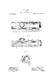
- the object of the invention is to provide improved means for holding the glass to its seat; and it consists of a structure as hereinafter described and as illustrated in the accompanying drawings, in which- Figure l is a front elevation of the lamp partly in vertical section and some parts being broken away; Fig. 2 is a bottom plan view of the lamp partly in horizontal sec tion with some parts broken away; and F 1g. 3 is a sectional view on the line 3-3 of Fig. 1.
- the body 10 of the lamp is preferably made of sheet metal, and takes the form of a. horizontal tube or, moreproperly speaking, is U-shaped in cross-section. One arm of the U projects downwardly, as shown at 11, and is folded back upon 1tself, as shown at 12, thereby providing an attaching plate. perforated to accommodate screws for securing the lamp to a support.
- the leaf 12 of the attaching plate s flanged inwardly at its extreme edge, as shown at 13, and a similar mturned flange 14 on the shorter arm of the U-shaped body provides a seat for a glass plate l5 which closes the downwardly directed light-emitting aperture of the lamp.
- a reflec tor plate 16, bent to U form, is fitted within the body of the lamp and 1s flanged inwardly along its bottom edges, as shown at 17, 18.
- a cushioning device is inserted between the bow of the reflector and the bow of the lamp body.
- This cushioning device may be formed of any yielding material.
- a leaf spring 19 secured midway of its ends, as
- the glass plate is inserted from one 811(1 and is held in place by means of an end plate 21. secured to the end of the body or the lamp by a screw cap 22, which passes through an aperture in the plate '21 and is in threaded engagement with a block 9.3 secured within the lamp body.
- A. socket 24 for holding an incandescent bulb 25 is secured within the opposite end of the body. and a lateral light mitting aperture is provided at 26 and, in ordinary practice. is supplied with a colored lens.
- a lamp in combination, a chambered body having a light-emitting aperture provided at its margins with a seat for a glass plate, a reflector having inturned marginal flanges facing the seat for engaging a glass plate mounted thereon, and a spring'reactmg between the back of the reflector and an inner wall of the body and holding the re. tlector against the seat.
- a body U- shaped in cross section and having its side walls flanged inward.
- a glass plate seated against the inner faces of the flanges, a reflector forming a liningfor the body and U-shaped in cross-section and having its side walls flanged inward to bear on the inner face of the glam. and a'sp'ring reacting between the bows of the body and the reflector.
- a lamp in combination, an oblong casing having an open side, a slideway along such open side, such slideway being open able at one end. the inner walls of such slideway being spring advanced, and a glass plate seated within the slideway.
Landscapes
- Engineering & Computer Science (AREA)
- General Engineering & Computer Science (AREA)
- Lighting Device Outwards From Vehicle And Optical Signal (AREA)
Description
W. S. HAMM.
LAMP.
APPLICATION FILED JUNE 26. 1912.
Patented Nov. 17, 1914.
UNITED STA'IildS Pi iTENT WILLIAM S. HAMM,-OF HUBBARD WOODS. ILLINOIS. ASSIGNOR TO THfi'h -iJAIVIS & WESTLAKE COMPANY. A CORPORATION OF ILLINOIS.
LAMP.
Specification of Letters Patent.
Patented Nov. 17. 1914.
Application filed il'une 26. 1912. Serial No. 105.950.
To all whom it may concern:
lc it known that I. 'ILLLUI I'IAMM, a citizen of the United States, and resident of Hubbard ll'cods, county of Cook. and State of Illinois, have invented certain new and useful Improvements in Lamps, of which the following is a specification, and which are illustrated in the accon'ipanying drawings, forming a part thereof.
TllelDTQlltlOil relates to tail lamps for vehicles, and of the type which comprise a tubular form of bodyhaving a glass-closed light-emitting aperture along one of its sides.
The object of the invention is to provide improved means for holding the glass to its seat; and it consists of a structure as hereinafter described and as illustrated in the accompanying drawings, in which- Figure l is a front elevation of the lamp partly in vertical section and some parts being broken away; Fig. 2 is a bottom plan view of the lamp partly in horizontal sec tion with some parts broken away; and F 1g. 3 is a sectional view on the line 3-3 of Fig. 1.
The body 10 of the lamp is preferably made of sheet metal, and takes the form of a. horizontal tube or, moreproperly speaking, is U-shaped in cross-section. One arm of the U projects downwardly, as shown at 11, and is folded back upon 1tself, as shown at 12, thereby providing an attaching plate. perforated to accommodate screws for securing the lamp to a support.
The leaf 12 of the attaching plate s flanged inwardly at its extreme edge, as shown at 13, and a similar mturned flange 14 on the shorter arm of the U-shaped body provides a seat for a glass plate l5 which closes the downwardly directed light-emitting aperture of the lamp. A reflec tor plate 16, bent to U form, is fitted within the body of the lamp and 1s flanged inwardly along its bottom edges, as shown at 17, 18.
to bear upon the glass plate 15. In order to provide a yielding engagement between the flanges of the reflector and the glass plate,
' and thereby prevent the glass from rattling in its seat, a cushioning device is inserted between the bow of the reflector and the bow of the lamp body. This cushioning device may be formed of any yielding material. There is shown for that purpose a leaf spring 19, secured midway of its ends, as
indicated at '10, to the lampb'ody, the spring being bowed downwardly to bear-upon the ba k of the reflector.
The glass plate is inserted from one 811(1 and is held in place by means of an end plate 21. secured to the end of the body or the lamp by a screw cap 22, which passes through an aperture in the plate '21 and is in threaded engagement with a block 9.3 secured within the lamp body.
A. socket 24 for holding an incandescent bulb 25 is secured within the opposite end of the body. and a lateral light mitting aperture is provided at 26 and, in ordinary practice. is supplied with a colored lens.
I claim as my invention 1. In a lamp, in combination, a chambered body having a light-emitting aperture provided at its margins with a seat for a glass plate, a reflector having inturned marginal flanges facing the seat for engaging a glass plate mounted thereon, and a spring'reactmg between the back of the reflector and an inner wall of the body and holding the re. tlector against the seat.
2. In a lamp, in combination, a body U- shaped in cross section and having its side walls flanged inward. a glass plate seated against the inner faces of the flanges, a reflector forming a liningfor the body and U-shaped in cross-section and having its side walls flanged inward to bear on the inner face of the glam. and a'sp'ring reacting between the bows of the body and the reflector.
3. In a lamp, in combination, a body U- shaped in cross section and having its side walls parallel and flanged inward at their margins; a glass plate seated against the inner faces of the flanges, a removable element for engaging the end ,of the glass plate, a reflector forming a lining for the body and Ushaped in cross section and having its side walls flanged inward to bear on the inner face of the glass and a spring reactingbetween the bows of the body and of the re- 'flector.
4:. In a lamp, in combination, an oblong casing having an open side, a slideway along such open side, such slideway being open able at one end. the inner walls of such slideway being spring advanced, and a glass plate seated within the slideway.
5. In a lamp, in combination, an oblong casing U-shape in cross section. the margin ingly holding the glass plate.
fle ctor walls and the casing flanges consti- -of its side walls being fiangc inwarcl, 2t electric "bulb supported one and glass plate seated against the flanges, a U- shape reflector within the casing, a sprlng of the casing, fiangeson the casing for retaining the, glass plate, aU-shaped reflector Within the casing, a spring urging the reflcctor toward the glass plate, the margins of the reflector and the flanges of the casing forming a yielding slideway for the plate. WILLIAM S. HAMM;
urging" the side walls of the rcflctor toward the casing flanges, the margins of the re tut'mg walls for slidably receiving and yield- 6. In a lamp of the kiwi filescribed, in
combination, an oblong casing having an open side, a glass plate closingsuch open Witnesses:
" Lon-1s K. GrLLsoN,
E. M. KLATCHER.
Copies of this patant may be obtained for five cents esch, by azlrsssing the fiomnsissioner o! latenta Washington n, 3,
Priority Applications (1)
| Application Number | Priority Date | Filing Date | Title |
|---|---|---|---|
| US70595012A US1117841A (en) | 1912-06-26 | 1912-06-26 | Lamp. |
Applications Claiming Priority (1)
| Application Number | Priority Date | Filing Date | Title |
|---|---|---|---|
| US70595012A US1117841A (en) | 1912-06-26 | 1912-06-26 | Lamp. |
Publications (1)
| Publication Number | Publication Date |
|---|---|
| US1117841A true US1117841A (en) | 1914-11-17 |
Family
ID=3186017
Family Applications (1)
| Application Number | Title | Priority Date | Filing Date |
|---|---|---|---|
| US70595012A Expired - Lifetime US1117841A (en) | 1912-06-26 | 1912-06-26 | Lamp. |
Country Status (1)
| Country | Link |
|---|---|
| US (1) | US1117841A (en) |
-
1912
- 1912-06-26 US US70595012A patent/US1117841A/en not_active Expired - Lifetime
Similar Documents
| Publication | Publication Date | Title |
|---|---|---|
| US1478282A (en) | Flash light | |
| US2423664A (en) | Headlight lens | |
| US1117841A (en) | Lamp. | |
| US1045852A (en) | Lens and reflector retainer for lamp-doors. | |
| US1562875A (en) | Automobile headlight | |
| US721648A (en) | Adjustable means for mounting reflectors. | |
| US1069035A (en) | Shade-reflector. | |
| US1029356A (en) | Globe and globe-holder. | |
| US1658551A (en) | Adjustable light support for reflectors | |
| US1183147A (en) | Mine-lamp. | |
| US996662A (en) | Lamp. | |
| US973235A (en) | Illuminating device and reflector. | |
| US1381637A (en) | Illuminating apparatus | |
| US1786814A (en) | Lamp focusing mechanism | |
| US1446925A (en) | Nonglare shade for automobile lamps | |
| US1485614A (en) | Adjustable electric-lamp support for candle tubes | |
| US1225051A (en) | Portable electric lamp. | |
| US1575548A (en) | Electric-lamp mounting | |
| US1137379A (en) | Show-case light. | |
| US1137221A (en) | Headlight attachment. | |
| US1040412A (en) | Light-reflector for automobile-lamps. | |
| US967161A (en) | Signal-lamp. | |
| US1779953A (en) | Focusing device | |
| US529105A (en) | Reflector and shade for lamps | |
| US1694592A (en) | Lamp |