US1117455A - Churn. - Google Patents
Churn. Download PDFInfo
- Publication number
- US1117455A US1117455A US84151914A US1914841519A US1117455A US 1117455 A US1117455 A US 1117455A US 84151914 A US84151914 A US 84151914A US 1914841519 A US1914841519 A US 1914841519A US 1117455 A US1117455 A US 1117455A
- Authority
- US
- United States
- Prior art keywords
- shaft
- dasher
- churn
- lever
- standard
- Prior art date
- Legal status (The legal status is an assumption and is not a legal conclusion. Google has not performed a legal analysis and makes no representation as to the accuracy of the status listed.)
- Expired - Lifetime
Links
- 235000014121 butter Nutrition 0.000 description 3
- 238000010276 construction Methods 0.000 description 2
- 239000006071 cream Substances 0.000 description 2
- 235000015243 ice cream Nutrition 0.000 description 2
- 230000003534 oscillatory effect Effects 0.000 description 2
- 241000592817 Caddo Species 0.000 description 1
- 238000010009 beating Methods 0.000 description 1
- 238000006073 displacement reaction Methods 0.000 description 1
- 210000005069 ears Anatomy 0.000 description 1
- 230000000630 rising effect Effects 0.000 description 1
Images

Classifications
-
- F—MECHANICAL ENGINEERING; LIGHTING; HEATING; WEAPONS; BLASTING
- F01—MACHINES OR ENGINES IN GENERAL; ENGINE PLANTS IN GENERAL; STEAM ENGINES
- F01B—MACHINES OR ENGINES, IN GENERAL OR OF POSITIVE-DISPLACEMENT TYPE, e.g. STEAM ENGINES
- F01B1/00—Reciprocating-piston machines or engines characterised by number or relative disposition of cylinders or by being built-up from separate cylinder-crankcase elements
- F01B1/06—Reciprocating-piston machines or engines characterised by number or relative disposition of cylinders or by being built-up from separate cylinder-crankcase elements with cylinders in star or fan arrangement
- F01B1/0641—Details, component parts specially adapted for such machines
- F01B1/0668—Supporting and guiding means for the piston
-
- Y—GENERAL TAGGING OF NEW TECHNOLOGICAL DEVELOPMENTS; GENERAL TAGGING OF CROSS-SECTIONAL TECHNOLOGIES SPANNING OVER SEVERAL SECTIONS OF THE IPC; TECHNICAL SUBJECTS COVERED BY FORMER USPC CROSS-REFERENCE ART COLLECTIONS [XRACs] AND DIGESTS
- Y10—TECHNICAL SUBJECTS COVERED BY FORMER USPC
- Y10T—TECHNICAL SUBJECTS COVERED BY FORMER US CLASSIFICATION
- Y10T74/00—Machine element or mechanism
- Y10T74/18—Mechanical movements
- Y10T74/18024—Rotary to reciprocating and rotary
Definitions
- the invention relates to improvements in churns.
- the object of the present invention is to improve the construction of churns and to provide a simple, practical, and efficient churn, of strong, durable, and inexpensive construction, capable of easy operation, and adapted to rapidly produce butter and gather the same.
- a further object of the invention is to provide a churn of this character equipped with a plurality of dashers and adapted to be advantageously employed for various operations requiringa dasher, such as the making of ice cream, cake batter, beating.
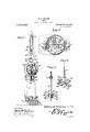
- Fig. 2 is a transverse sectional view of the same.
- Fig. 3 is a horizontal sectional view on the line 3-3 of F ig. 1.
- Fig. 4 is a detail perspective view of the vertical reciprocating dasher.
- Fig. 5 is a similar view of the rotary dasher.
- 1 designates a churn body mounted upon a base 2 and prefe ably detachably secured upon the same by means of bolts 3 or other suitable fastening devices, which are arranged in registering perforations of horizontal flanges 4 of the churn body and approximately L-shaped arms 5 of the base.
- the flanges 4 are preferably Specification of Letters Patent.
- the llai'iges may be constructed in any other desired manner.
- the L-shaped arms 5, which consist of vertical upwardly extending portions and horizontal top portions, are provided with bottom attaching portions 7, which are bolted or otherwise secured to the upper face of the base Any other suitable means, however, may be employed for rigidly securing the churn body 1n position on the base.
- the base which is provided at its lower face with transverse supporting cleats 8, is recessed at its rear end to receive the lower portion of a stand ard S), which has its lower end arranged in [lush relation with the adjacent supporting cleat 8. l
- the churn body is equipped with a cover 10 provided with a bearing opeuing ll for the shaft 12 of a lower rotary dashcr 13, and the said cover 10 is also provided with a slot l l, through which passes the stem 15 of an upper vertically reciprocating dasher 1.6.
- the shaft 12 has its lower end 17 stepped in a suitable bearing 18, and it is provided at its upper portion with a collar or enlargement 19, which [its against the lower face of the lid or cover of the churn body, whereby the shaft 12 is held against vertical displacement and maintained in proper position while the churn is in use.
- the rotary dashcr 13 consists of a plurality of radially arranged approximately U-shapcd arms 20, which are secured to and extend from a lower polygonal enlargement 21 of the shaft 12.
- the polygonal portion 21 of the shaft rests upon the lower bearing 18, which is suitably secured to the bottom of the churn body.
- the upper dasher 16 consists of a horizontally disposed approximately oblong body portion and horizontal blades 22, extending from opposite sides of the body ortion.
- the body portion is provided with opposite recesses 23, and the blades have apertures 24.
- One of the recesses 23 receives the shaft 12 of the rotary dasher, which is adapted to operate as a guide for the vertically reciprocating d sher.
- the shaft 12 of the rotary dasher is provided at its upper end with a head 25 having a socket 26 to receive the upper end of the shaft. and secured to the same by a bolt 27.
- the head of the shaft constitutes a gear element, and is preferably in the form of a pulley having a groove 28, to receive a belt 29, and which is also arranged in a groove 30 of a pulley 31, carried by a vertical shaft
- sprocket gearing may be used for transmitting motion from the vertical shaft to the dasher shaft 12.
- the vertical shaft 32 has reduced lower portions 33 and 34, journaled in suitable bearings of upper and lower arms 35 and 36 of a bearing bracket 37, which is mounted upon the standard 9, at the front face thereof.
- the vertical shaft carries a horizontal bevel gear 38, which meshes with a vertical bevel gear 39, mounted on the inner end of an operating shaft 4-0.
- the operating shaft 40 extends through and is journaled in a suitable bearing opening of the standard, and it has keyed or otherwise secured to its rear end a vertical spur gear wheel 40, provided with an eccentrically arranged handle fl and meshing with a spur pinion a2.
- the spur pinion is fixed to the rear end of a countershaft 43, extending through and journaled in a suitable bearing opening of the standard, and equipped at its front end with a crank element a l, which is connected by a pitman to with the inner end of an oscillatory lever i6.
- the lever lG is pivoted at a point intermediate of its ends between depending ears :7 of an arm 48 of the standard by a pin or bolt l9.
- the outer end of the lever 16 is enlarged and is provided with spaced depending portions or flanges 50, between which is pivoted the upper end 51 of the stem 15 of the dasher 16.
- the stem is provided at its upper end 51 with an through which passes a movable pin 52, which is also arranged in perforations of the spaced depending portions or flanges 50 of the oscillatory lever.
- the inner end of the lever 46 is arranged between spaced guides 53, depending from the inner portion of the arm 4L8, and adapted to prevent lateral. movement of the lever.
- the countershaf-t oscillates the lever 4:6, which reciprocates the dasher l6, ,and the vertical shaft 32 rotates the dasher shaft 12.
- the slot 14- in the lid or cover 10 is of sufficient length to permit the lateral movement or play of the stem of the vertically reciprocating dasher.
- the upper dasher operates to beat the cream quickly into butter, and the lower dasher has a tendency to gather the cream and float it to the top, where it will be operated on by the upper dasher.
- the coacting upper and lower dashers are adapted to rapidly produce butter, and the upper dasher may be removed when it is desired to use .the churn for other purposes, such as the making of ice cream, cake batter, and other operations requiring an agitator.
- the gearing and other operating mechanism By mounting the gearing and other operating mechanism on the standard, above and beyond the churn body, the churn is especially adapted to be employed for other purposes, and other receptacles and agitators may be substituted for the churn body and the upper and lower dashers.
- a churn including a standard having a projecting arm provided at the inner portion with spaced depending guides, an operating lever pivoted at an intermediate point to the outer portion of the arm of the standard and having its inner portion operating between the said spaced guides, a.
- churn body a reciprocating dasher having a stem connected with the outer end of the lever, a rotary dasher havlng a shaft, a
- A. churn comprising a base, a standard rising from the base and having an arm extending over the same, a churn body, a rotary dasher mounted within the churn body and having a shaft extending above the same, a vertically reciprocating dasher having a stem projecting above the churn body, a lever fulcrumed at an intermediate pointat the outer end of the arm and supported by the latter, the outer arm of the lever being connected with the said dasher stem, a vertical shaft mounted on the standard, means for transmitting motion from the vertical shaft to the dasher shaft, upper and lower shafts ournaled on the standard, the upper shaft being provided with a crank element connected with the innerarm of the said lever, gearing for connecting the lower shaft with the vertical shaft, and gears connecting the upper and lower shafts with each other, one of such gears being provided with operating means.
Landscapes
- Engineering & Computer Science (AREA)
- Mechanical Engineering (AREA)
- General Engineering & Computer Science (AREA)
- Dairy Products (AREA)
Description
W. B. SIMPSON.
GHURN.
APPLICATION FILED MAY 20. 1014.
1 ,1 17,455, Patefited Nov. 17, 1914.
2 SHEETS SHEBT 1.
4517774060775 NVENTOR WITNESSES ATTO R N EY 1H5 HURRY]; PETERS (70-, PHOTD-LITHO-, WASHINGTON. Dv C.
W. B. SIMPSON.
CHURN.
APPLIOATION FILED MAY 23, 1914.
1 ,1 17,455, Patented Nov. 17. 1914.
2 SHEETS'SHEET 2 8 Him I 'SOTl/INVENTOR WITNESSES In!) ATTORNEY Unrrnn s'rA'rEs PATENT oFFicn.
WILLIAM BUTLER SIMPSON, OF SHREVEPORT, LOUISIANA,
CI'IURN.
To all whom it may concern:
.Be it known that I, WiLLIAM B. SIMPSON, a citizen of the United States, residing at Shreveport, in the parish of Caddo and State of Louisiana, have invented a new and useful Churn, of which the fpllowing is a specification.
The invention relates to improvements in churns.
The object of the present invention .is to improve the construction of churns and to provide a simple, practical, and efficient churn, of strong, durable, and inexpensive construction, capable of easy operation, and adapted to rapidly produce butter and gather the same.
A further object of the invention is to provide a churn of this character equipped with a plurality of dashers and adapted to be advantageously employed for various operations requiringa dasher, such as the making of ice cream, cake batter, beating.
churn constructed in accordance with this invention. Fig. 2 is a transverse sectional view of the same. Fig. 3 is a horizontal sectional view on the line 3-3 of F ig. 1. Fig. 4 is a detail perspective view of the vertical reciprocating dasher. Fig. 5 is a similar view of the rotary dasher.
Like numerals of reference designate corresponding parts in all the figures of the drawings.
In the accompanying drawings, in which is illustrated the preferred embodiment of the invention, 1 designates a churn body mounted upon a base 2 and prefe ably detachably secured upon the same by means of bolts 3 or other suitable fastening devices, which are arranged in registering perforations of horizontal flanges 4 of the churn body and approximately L-shaped arms 5 of the base. The flanges 4 are preferably Specification of Letters Patent.
Application filed May 28. 1914.
Patented Nov. 17, 1914.
Serial No. 841,519.
formed by angle plates 6 secured to the exterior of the churn body near the bottom thereof, but the llai'iges may be constructed in any other desired manner. The L-shaped arms 5, which consist of vertical upwardly extending portions and horizontal top portions, are provided with bottom attaching portions 7, which are bolted or otherwise secured to the upper face of the base Any other suitable means, however, may be employed for rigidly securing the churn body 1n position on the base. The base, which is provided at its lower face with transverse supporting cleats 8, is recessed at its rear end to receive the lower portion of a stand ard S), which has its lower end arranged in [lush relation with the adjacent supporting cleat 8. l
The churn body is equipped with a cover 10 provided with a bearing opeuing ll for the shaft 12 of a lower rotary dashcr 13, and the said cover 10 is also provided with a slot l l, through which passes the stem 15 of an upper vertically reciprocating dasher 1.6. The shaft 12 has its lower end 17 stepped in a suitable bearing 18, and it is provided at its upper portion with a collar or enlargement 19, which [its against the lower face of the lid or cover of the churn body, whereby the shaft 12 is held against vertical displacement and maintained in proper position while the churn is in use. The rotary dashcr 13 consists of a plurality of radially arranged approximately U-shapcd arms 20, which are secured to and extend from a lower polygonal enlargement 21 of the shaft 12. The polygonal portion 21 of the shaft rests upon the lower bearing 18, which is suitably secured to the bottom of the churn body. The upper dasher 16 consists of a horizontally disposed approximately oblong body portion and horizontal blades 22, extending from opposite sides of the body ortion. The body portion is provided with opposite recesses 23, and the blades have apertures 24. One of the recesses 23 receives the shaft 12 of the rotary dasher, which is adapted to operate as a guide for the vertically reciprocating d sher.
The shaft 12 of the rotary dasher is provided at its upper end with a head 25 having a socket 26 to receive the upper end of the shaft. and secured to the same by a bolt 27. The head of the shaft constitutes a gear element, and is preferably in the form of a pulley having a groove 28, to receive a belt 29, and which is also arranged in a groove 30 of a pulley 31, carried by a vertical shaft Instead of employing a plain belt or cord, sprocket gearing may be used for transmitting motion from the vertical shaft to the dasher shaft 12. The vertical shaft 32 has reduced lower portions 33 and 34, journaled in suitable bearings of upper and lower arms 35 and 36 of a bearing bracket 37, which is mounted upon the standard 9, at the front face thereof. The vertical shaft carries a horizontal bevel gear 38, which meshes with a vertical bevel gear 39, mounted on the inner end of an operating shaft 4-0. The operating shaft 40 extends through and is journaled in a suitable bearing opening of the standard, and it has keyed or otherwise secured to its rear end a vertical spur gear wheel 40, provided with an eccentrically arranged handle fl and meshing with a spur pinion a2. The spur pinion is fixed to the rear end of a countershaft 43, extending through and journaled in a suitable bearing opening of the standard, and equipped at its front end with a crank element a l, which is connected by a pitman to with the inner end of an oscillatory lever i6. The lever lG is pivoted at a point intermediate of its ends between depending ears :7 of an arm 48 of the standard by a pin or bolt l9. The outer end of the lever 16 is enlarged and is provided with spaced depending portions or flanges 50, between which is pivoted the upper end 51 of the stem 15 of the dasher 16. The stem is provided at its upper end 51 with an through which passes a movable pin 52, which is also arranged in perforations of the spaced depending portions or flanges 50 of the oscillatory lever. The inner end of the lever 46 is arranged between spaced guides 53, depending from the inner portion of the arm 4L8, and adapted to prevent lateral. movement of the lever.
lVhen the large gear wheel 40* is rotated, the motion is communicated simultaneously to the upper countershaft 4:3 and the vertical shaft The countershaf-t oscillates the lever 4:6, which reciprocates the dasher l6, ,and the vertical shaft 32 rotates the dasher shaft 12. The slot 14- in the lid or cover 10 is of sufficient length to permit the lateral movement or play of the stem of the vertically reciprocating dasher. The upper dasher operates to beat the cream quickly into butter, and the lower dasher has a tendency to gather the cream and float it to the top, where it will be operated on by the upper dasher. The coacting upper and lower dashers are adapted to rapidly produce butter, and the upper dasher may be removed when it is desired to use .the churn for other purposes, such as the making of ice cream, cake batter, and other operations requiring an agitator. By mounting the gearing and other operating mechanism on the standard, above and beyond the churn body, the churn is especially adapted to be employed for other purposes, and other receptacles and agitators may be substituted for the churn body and the upper and lower dashers.
What is claimed is 1. A churn including a standard having a projecting arm provided at the inner portion with spaced depending guides, an operating lever pivoted at an intermediate point to the outer portion of the arm of the standard and having its inner portion operating between the said spaced guides, a.
churn body, a reciprocating dasher having a stem connected with the outer end of the lever, a rotary dasher havlng a shaft, a
vertical shaft mounted on the standard, pulleys carried by the vertical shaft and" the dasher shaft, a belt connecting the said pulleys, upper and lower shafts mounted on the standard, the upper shaft having a crank element connected with the inner end of the lever, and gearing connecting the upper and lower shafts with each other and with the vertical shaft and having operating means.
2. A. churn comprising a base, a standard rising from the base and having an arm extending over the same, a churn body, a rotary dasher mounted within the churn body and having a shaft extending above the same, a vertically reciprocating dasher having a stem projecting above the churn body, a lever fulcrumed at an intermediate pointat the outer end of the arm and supported by the latter, the outer arm of the lever being connected with the said dasher stem, a vertical shaft mounted on the standard, means for transmitting motion from the vertical shaft to the dasher shaft, upper and lower shafts ournaled on the standard, the upper shaft being provided with a crank element connected with the innerarm of the said lever, gearing for connecting the lower shaft with the vertical shaft, and gears connecting the upper and lower shafts with each other, one of such gears being provided with operating means.
In testimony that I claim the foregoing as my own, I have hereto afliXed my signature in the presence of two witnesses.
WILLIAM BUTLER SIMPSON. lVitnesses R. E. WVYoI-In,
S. V. KERLEY.
Copies of this patent may be obtained for five cents each, by addressing the Commissioner of Patents Washington, D. G.
Priority Applications (1)
| Application Number | Priority Date | Filing Date | Title |
|---|---|---|---|
| US84151914A US1117455A (en) | 1914-05-28 | 1914-05-28 | Churn. |
Applications Claiming Priority (1)
| Application Number | Priority Date | Filing Date | Title |
|---|---|---|---|
| US84151914A US1117455A (en) | 1914-05-28 | 1914-05-28 | Churn. |
Publications (1)
| Publication Number | Publication Date |
|---|---|
| US1117455A true US1117455A (en) | 1914-11-17 |
Family
ID=3185631
Family Applications (1)
| Application Number | Title | Priority Date | Filing Date |
|---|---|---|---|
| US84151914A Expired - Lifetime US1117455A (en) | 1914-05-28 | 1914-05-28 | Churn. |
Country Status (1)
| Country | Link |
|---|---|
| US (1) | US1117455A (en) |
Cited By (1)
| Publication number | Priority date | Publication date | Assignee | Title |
|---|---|---|---|---|
| US2431298A (en) * | 1944-03-01 | 1947-11-18 | Marvin R Wallace | Machine for reciprocating and rotating churn dashers |
-
1914
- 1914-05-28 US US84151914A patent/US1117455A/en not_active Expired - Lifetime
Cited By (1)
| Publication number | Priority date | Publication date | Assignee | Title |
|---|---|---|---|---|
| US2431298A (en) * | 1944-03-01 | 1947-11-18 | Marvin R Wallace | Machine for reciprocating and rotating churn dashers |
Similar Documents
| Publication | Publication Date | Title |
|---|---|---|
| US1117455A (en) | Churn. | |
| US941948A (en) | Churn. | |
| US60097A (en) | Improvement in ghoshs | |
| US217263A (en) | Improvement in churns | |
| US262118A (en) | Molds | |
| US88320A (en) | Improvement in churns | |
| US830336A (en) | Churn. | |
| US727094A (en) | Churn. | |
| US955672A (en) | Egg-beater. | |
| US1020300A (en) | Rotary churn. | |
| US438165A (en) | Churn | |
| US190581A (en) | Improvement in rotary churns | |
| US267368A (en) | Churn | |
| US282047A (en) | Churn | |
| US210090A (en) | Improvement in churns | |
| US37016A (en) | Improvement in churns | |
| US60493A (en) | elder | |
| US1070147A (en) | Churn. | |
| US188863A (en) | Improvement in churns | |
| US249384A (en) | Ice-cream freezer | |
| US346180A (en) | Rotary churn | |
| US639330A (en) | Churn. | |
| US1030356A (en) | Combined churn and butter-worker. | |
| US358569A (en) | Motor for churns | |
| US168218A (en) | Improvement in churns |