US11174007B2 - Flow control apparatus, flow control method, and aircraft - Google Patents
Flow control apparatus, flow control method, and aircraft Download PDFInfo
- Publication number
- US11174007B2 US11174007B2 US16/197,668 US201816197668A US11174007B2 US 11174007 B2 US11174007 B2 US 11174007B2 US 201816197668 A US201816197668 A US 201816197668A US 11174007 B2 US11174007 B2 US 11174007B2
- Authority
- US
- United States
- Prior art keywords
- flow state
- air flow
- state
- voltage waveform
- waveform
- Prior art date
- Legal status (The legal status is an assumption and is not a legal conclusion. Google has not performed a legal analysis and makes no representation as to the accuracy of the status listed.)
- Active, expires
Links
- 238000000034 method Methods 0.000 title description 15
- 230000032798 delamination Effects 0.000 claims description 77
- 230000008859 change Effects 0.000 claims description 48
- 230000001629 suppression Effects 0.000 claims description 26
- 230000004044 response Effects 0.000 claims description 12
- 230000001965 increasing effect Effects 0.000 claims description 8
- 230000003247 decreasing effect Effects 0.000 claims description 4
- 239000007789 gas Substances 0.000 description 23
- 238000012360 testing method Methods 0.000 description 22
- 238000009826 distribution Methods 0.000 description 13
- 238000004088 simulation Methods 0.000 description 12
- 230000000694 effects Effects 0.000 description 10
- 230000006870 function Effects 0.000 description 8
- 230000003068 static effect Effects 0.000 description 5
- 230000004888 barrier function Effects 0.000 description 4
- 230000015572 biosynthetic process Effects 0.000 description 4
- 238000005094 computer simulation Methods 0.000 description 4
- 239000012530 fluid Substances 0.000 description 4
- 230000008569 process Effects 0.000 description 4
- 238000010586 diagram Methods 0.000 description 3
- 230000001939 inductive effect Effects 0.000 description 2
- 238000010801 machine learning Methods 0.000 description 2
- 238000012986 modification Methods 0.000 description 2
- 230000004048 modification Effects 0.000 description 2
- 238000000926 separation method Methods 0.000 description 2
- 230000001133 acceleration Effects 0.000 description 1
- 239000000446 fuel Substances 0.000 description 1
- 239000002737 fuel gas Substances 0.000 description 1
- 230000006698 induction Effects 0.000 description 1
- 229910052500 inorganic mineral Inorganic materials 0.000 description 1
- 150000002500 ions Chemical class 0.000 description 1
- 239000010410 layer Substances 0.000 description 1
- 239000000463 material Substances 0.000 description 1
- 239000011707 mineral Substances 0.000 description 1
- 239000002245 particle Substances 0.000 description 1
- 238000004904 shortening Methods 0.000 description 1
- 238000009751 slip forming Methods 0.000 description 1
- 238000006467 substitution reaction Methods 0.000 description 1
- 239000002344 surface layer Substances 0.000 description 1
- 239000010409 thin film Substances 0.000 description 1
Images


Classifications
-
- F—MECHANICAL ENGINEERING; LIGHTING; HEATING; WEAPONS; BLASTING
- F15—FLUID-PRESSURE ACTUATORS; HYDRAULICS OR PNEUMATICS IN GENERAL
- F15D—FLUID DYNAMICS, i.e. METHODS OR MEANS FOR INFLUENCING THE FLOW OF GASES OR LIQUIDS
- F15D1/00—Influencing flow of fluids
- F15D1/002—Influencing flow of fluids by influencing the boundary layer
- F15D1/0065—Influencing flow of fluids by influencing the boundary layer using active means, e.g. supplying external energy or injecting fluid
- F15D1/0075—Influencing flow of fluids by influencing the boundary layer using active means, e.g. supplying external energy or injecting fluid comprising electromagnetic or electrostatic means for influencing the state of the fluid, e.g. for ionising the fluid or for generating a plasma
-
- B—PERFORMING OPERATIONS; TRANSPORTING
- B64—AIRCRAFT; AVIATION; COSMONAUTICS
- B64C—AEROPLANES; HELICOPTERS
- B64C21/00—Influencing air flow over aircraft surfaces by affecting boundary layer flow
-
- B—PERFORMING OPERATIONS; TRANSPORTING
- B64—AIRCRAFT; AVIATION; COSMONAUTICS
- B64C—AEROPLANES; HELICOPTERS
- B64C23/00—Influencing air flow over aircraft surfaces, not otherwise provided for
- B64C23/005—Influencing air flow over aircraft surfaces, not otherwise provided for by other means not covered by groups B64C23/02 - B64C23/08, e.g. by electric charges, magnetic panels, piezoelectric elements, static charges or ultrasounds
-
- B—PERFORMING OPERATIONS; TRANSPORTING
- B64—AIRCRAFT; AVIATION; COSMONAUTICS
- B64C—AEROPLANES; HELICOPTERS
- B64C9/00—Adjustable control surfaces or members, e.g. rudders
- B64C9/14—Adjustable control surfaces or members, e.g. rudders forming slots
- B64C9/16—Adjustable control surfaces or members, e.g. rudders forming slots at the rear of the wing
- B64C9/18—Adjustable control surfaces or members, e.g. rudders forming slots at the rear of the wing by single flaps
-
- B—PERFORMING OPERATIONS; TRANSPORTING
- B64—AIRCRAFT; AVIATION; COSMONAUTICS
- B64C—AEROPLANES; HELICOPTERS
- B64C2230/00—Boundary layer controls
- B64C2230/12—Boundary layer controls by using electromagnetic tiles, fluid ionizers, static charges or plasma
-
- Y—GENERAL TAGGING OF NEW TECHNOLOGICAL DEVELOPMENTS; GENERAL TAGGING OF CROSS-SECTIONAL TECHNOLOGIES SPANNING OVER SEVERAL SECTIONS OF THE IPC; TECHNICAL SUBJECTS COVERED BY FORMER USPC CROSS-REFERENCE ART COLLECTIONS [XRACs] AND DIGESTS
- Y02—TECHNOLOGIES OR APPLICATIONS FOR MITIGATION OR ADAPTATION AGAINST CLIMATE CHANGE
- Y02T—CLIMATE CHANGE MITIGATION TECHNOLOGIES RELATED TO TRANSPORTATION
- Y02T50/00—Aeronautics or air transport
- Y02T50/10—Drag reduction
-
- Y—GENERAL TAGGING OF NEW TECHNOLOGICAL DEVELOPMENTS; GENERAL TAGGING OF CROSS-SECTIONAL TECHNOLOGIES SPANNING OVER SEVERAL SECTIONS OF THE IPC; TECHNICAL SUBJECTS COVERED BY FORMER USPC CROSS-REFERENCE ART COLLECTIONS [XRACs] AND DIGESTS
- Y02—TECHNOLOGIES OR APPLICATIONS FOR MITIGATION OR ADAPTATION AGAINST CLIMATE CHANGE
- Y02T—CLIMATE CHANGE MITIGATION TECHNOLOGIES RELATED TO TRANSPORTATION
- Y02T50/00—Aeronautics or air transport
- Y02T50/30—Wing lift efficiency
Definitions
- Examples of the present invention relate to a flow control apparatus, a flow control method, and an aircraft.
- DBD-PA is a plasma actuator in which electrodes are arranged across a dielectric, and plasma is generated only on one side of the dielectric by applying a high alternating-current (AC) voltage between the electrodes.
- AC alternating-current
- An aspect of the present invention provides a flow control apparatus including a plasma actuator, a storage device, and a control circuit.
- the plasma actuator is configured to cause discharge in a discharge area by applying an alternating-current (AC) voltage between electrodes to form an induced flow of gas.
- the electrodes are shifted relatively to each other with a dielectric disposed between the electrodes.
- the storage device is configured to store a changing condition of an AC voltage waveform for changing a gas flow state formed in a flow control area of gas from a first flow state to a second flow state by adding the induced flow of gas.
- the second flow state is different from the first flow state.
- the control circuit is configured to refer to the at least one changing condition of the AC voltage waveform stored in the storage device and control the AC voltage waveform based on the at least one changing condition of the AC voltage waveform, in a case of changing the gas flow state formed in the gas flow control area from the first flow state to the second flow state.
- An aspect of the present invention provides a flow control method including: forming a first flow state of gas by applying an alternating-current voltage having a first waveform to electrodes of a plasma actuator to induce flow of gas corresponding to the first waveform and adding the induced flow of the gas corresponding to the first waveform to a flow of the gas in a flow control area of the gas to form a first flow state of the gas; and forming a second flow state of the gas different from the first flow state by changing the alternating-current voltage waveform applied to the electrode of the plasma actuator from the first waveform to a second waveform different from the first waveform to induce a flow of the gas corresponding to the second waveform, and by adding the induced flow of the gas corresponding to the second waveform to the flow of the gas in the first flow state in the flow control area of the gas to forma second flow state different from the first flow state.
- FIG. 1 is a schematic view of a flow control apparatus according to a first example of the present invention.
- FIG. 2 is a schematic view illustrating a plasma actuator illustrated in FIG. 1 mounted on a wing structure of an aircraft.
- FIG. 3 is a graph illustrating an alternating-current (AC) voltage waveform of applied between a first electrode and a second electrode from an AC power supply of the plasma actuator illustrated in FIG. 1 .
- AC alternating-current
- FIG. 4 is a flowchart showing a progression of an air flow control process using the flow control apparatus illustrated in FIG. 1 .
- FIG. 5 is a flowchart showing another example of an air flow control process using the flow control apparatus illustrated in FIG. 1 .
- FIG. 6 is a schematic view of a flow control apparatus according to a second example of the present invention.
- FIG. 7 is a diagram illustrating a state in which a first electrode to which an AC voltage is to be applied is switched in the flow control apparatus illustrated in FIG. 6 .
- FIG. 8 is a schematic view of a flow control apparatus according to a third example of the present invention.
- FIG. 1 is a schematic view of a flow control apparatus according to a first example of the present invention.
- the flow control apparatus 1 is a system for controlling air flow around the airframe of the aircraft 2 . Accordingly, the flow control apparatus 1 is mounted on the aircraft 2 .
- the aircraft 2 may be a manned aircraft or an unmanned aircraft.
- the aircraft 2 may be a fixed-wing aircraft or a rotating-wing aircraft such as a helicopter.
- the flow control apparatus 1 comprises a plasma actuator 3 and a control system 4 for controlling the plasma actuator 3 .
- the control system 4 may be supplied with necessary instruction information from an input device 5 provided with the aircraft 2 or an input device 5 dedicated to the flow control apparatus 1 .
- the input device 5 may be provided inside the airframe of the aircraft 2 to enable a pilot or passenger to input instructional information to the control system 4 .
- the aircraft 2 is an unmanned aircraft, the input device 5 may be provided outside the airframe of the aircraft 2 so that instruction information is input to the control system 4 from a remote location. Further, when the aircraft 2 is automatically operated by a flight program, instruction information may be input to the control system 4 from a system for automatically operating the aircraft 2 .
- the plasma actuator 3 comprises a first electrode 6 , a second electrode 7 , a dielectric 8 , and an AC power supply 9 .
- the first electrode 6 and the second electrode 7 are arranged to be shifted relative to each other with the dielectric 8 interposed therebetween so that a discharge area is formed. That is, the second electrode 7 is shifted with respect to the first electrode 6 so that a discharge area is formed, and the dielectric 8 is disposed between the first electrode 6 and the second electrode 7 .
- the plasma actuator 3 which induces the dielectric barrier discharge by interposing the dielectric 8 between the first electrode 6 and the second electrode 7 , is called a DBD-PA.
- FIG. 2 is a diagram illustrating the plasma actuator 3 illustrated in FIG. 1 mounted on a wing structure 10 of an aircraft 2 .
- the first electrode 6 and the second electrode 7 constituting the plasma actuator 3 may each be in the form of a thin film. Therefore, as illustrated in FIG. 2 , the first electrode 6 and the second electrode 7 may be attached not only to a surface of the wing structure 10 , such as a stationary wing 11 or a movable wing 12 , but also to a surface of the fuselage, or embedded in a surface layer serving as an attachment position.
- a wing structure 10 such as a main wing, a horizontal tail wing or a vertical tail wing, which includes a movable wing 12 , is structured by connecting a movable wing 12 to a stationary wing 11 .
- the plasma actuator 3 may be used, for example, as an auxiliary apparatus for the movable wing 12 . More specifically, the plasma actuator 3 may be used for suppressing delamination of air flow on the wing surface of a movable wing 12 or reducing air resistance by reducing friction between the wing surface and air.
- the discharge area for generating plasma and the air flow control area are different from each other. That is, air flow induced by plasma generated in the discharge area is added to the uniform flow of air flowing along the wing surface of the blade structure 10 to which the plasma actuator 3 is attached so that a certain air flow condition is formed.
- the air flow control area is a region affected by the air flow induced by the plasma, including the downstream side of the air flow induced by the plasma.
- the position of the plasma actuator 3 is determined in such a way that the additional air flow induced by the plasma actuator 3 helps to achieve the desired air flow state in the air flow control area.
- the position of the plasma actuator 3 may be determined by wind tunnel testing or simulation.
- the control system 4 is a system for controlling the AC voltage waveform applied between the first electrode 6 and the second electrode 7 constituting the plasma actuator 3 .
- the control system 4 may be constituted by an electronic circuit including an electronic circuit such as a computer or storage circuit from which a program is read. That is, the control system 4 may be configured by a control circuit 13 and a storage device 14 .
- the control circuit 13 is a circuit for generating a control signal to be outputted to the AC power supply 9 of the plasma actuator 3 and controlling the AC power supply 9 via the generated control signal outputted to the AC power supply 9 . Accordingly, the control circuit 13 is connected to the AC power supply 9 of the plasma actuator 3 .
- control circuit 13 has a function of controlling the AC voltage waveform control for changing the air flow state formed in the air flow control area from a first flow state to a second flow state to be different from the first flow state, by adding induced air flow in the discharge area of the plasma actuator 3 to air flow formed in the air flow control area.
- the storage device 14 stores the changing conditions of the AC voltage waveform to operate the plasma actuator 3 and change the air flow state formed in the air flow control area from the first flow state to the second flow state. That is, a combination of the first flow state or the AC voltage waveform, being applied between the first electrode 6 and the second electrode 7 of the plasma actuator 3 for forming the first flow state, and the target second flow state may be stored in the storage device 14 as referential information in the form of a look-up table or functions, which are associated with the changed AC voltage waveform.
- the storage device 14 functions as a voltage waveform database for determining the AC voltage waveform to be applied between the first electrode 6 and the second electrode 7 to form the target second flow state based on the combination of the first flow state currently formed by operation of the plasma actuator 3 or the AC voltage waveform, being currently applied between the first electrode 6 and the second electrode 7 to form the current first flow state, and the target second flow state.
- the control circuit 13 may determine the AC voltage waveform to be applied between the first electrode 6 and the second electrode 7 to form the second flow state by referring to the changing conditions of the AC voltage waveform stored in the storage device 14 .
- the AC voltage waveform applied between the first electrode 6 and the second electrode 7 may be controlled in accordance with the changing conditions of the AC voltage waveform stored in the storage device 14 .
- the changing conditions of the AC voltage waveform stored in the storage device 14 may be obtained in advance by a wind tunnel test or a computer simulation.
- a wind tunnel test or a computer simulation is not used for determining the AC voltage waveform to be applied between the first electrode 6 and the second electrode 7 to form the target air flow state in the air flow control area by switching on the operation of the plasma actuator 3 from the air flow state formed in the air flow control area with the operation of the plasma actuator 3 being off, rather the wind tunnel test or the computer simulation is used for the purpose of determining the changing conditions of the AC voltage waveform for changing the first flow state formed in the air flow control area in a case where the operation plasma actuator 3 is already switched on to the second flow state while the plasma actuator 3 is kept on.
- the appropriate AC voltage waveform for forming the target air flow state in the air flow control area is different from the appropriate AC voltage waveform for forming another air flow state in the air flow control area when the operation of the plasma actuator 3 is already on. This is because the air flow state once formed in the air flow control area by the operation of the plasma actuator 3 does not immediately disappear even if the operation of the plasma actuator 3 is switched off due to the hysteresis of the air.
- the response delay of the air flow state formed in the air flow control area when the operation of the plasma actuator 3 is switched from the off state to the on state is the sum total of the period from the application of the AC voltage by the AC power supply 9 between the first electrode 6 and the second electrode 7 to the generation of plasma in the discharge area, the period from the acceleration of the charged particles in the plasma generated in the discharge area to the induction of air flow, and the period from the movement of induced air flow in the vicinity of the plasma along the wing surface of the blade structure 10 together with the uniform flow until the formation of the air flow state in the air flow control area.
- the air flow state is formed in the air flow control area with a certain response delay.
- the response delay in switching the operation of the plasma actuator 3 from the off state to the on state is predictable because it is proportional to the time that air flow induced in the vicinity of the plasma takes to move along the wing surface of the blade structure 10 .
- conditions of the AC voltage waveform to be applied between the first electrode 6 and the second electrode 7 of the plasma actuator 3 to change the air flow state formed in the air flow control area from the first flow state to the second flow state by operating the plasma actuator 3 may be obtained by wind tunnel tests or simulations taking hysteresis of the air into consideration.
- the conditions of the obtained AC voltage waveform may then be stored in the storage device 14 . This will make it possible to change the air flow state formed in the air flow control area from the first flow state to the second flow state by operating the plasma actuator 3 through control of the AC power supply 9 with the control circuit 13 together with reference to the referential information stored in the storage device 14 .
- FIG. 3 is a graph showing an example of an AC voltage waveform applied between the first electrode 6 and the second electrode 7 from the AC power supply 9 of the plasma actuator 3 shown in FIG. 1 .
- the vertical axis represents the voltage V
- the horizontal axis represents the time t.
- a waveform that cycles between a period in which the amplitude changes and a period in which the amplitude does not change, as shown in FIG. 3 is called a burst waveform, and a period T of the burst waveform is called a burst period.
- the ratio Ton/T of the period Ton in which the AC voltage of the amplitude Vm is successively applied to the burst period T corresponds to a duty ratio, and is called a burst ratio BR.
- the amplitude Vm of the AC voltage may be changed over time without being fixed, setting the amplitude Vm constant as shown in FIG. 3 leads to easier voltage control in the AC power supply 9 . Therefore, in the following description, the amplitude Vm of the AC voltage is assumed to be constant.
- the AC voltage waveform suitable for changing from the first flow state to the second flow state also includes a continuous wave corresponding to a waveform in which the burst ratio BR is 1, that is, the burst frequency f is infinite (the burst period T is zero).
- the changing conditions of an AC voltage waveform to change the air flow state formed in the air flow control area from a first flow state to a second flow state it is effective to store in the storage device 14 such a condition that a burst waveform having a first burst frequency is changed to a continuous waveform or a burst waveform having a second burst frequency different from the first burst frequency, so that the control circuit 13 changes the AC voltage waveform from a burst waveform having a first burst frequency to a continuous waveform or a burst waveform having a second burst frequency when the air flow state formed in the air flow control area is changed from a first flow state to a second flow state.
- the air flow is induced by switching the operation of the plasma actuator 3 from the off state to the on state, and after forming the first flow state in the air flow control area, the air flow induced by the operation of the plasma actuator 3 is returned to the flow state in the air flow control area before the induced air flow is added.
- the second flow state may be the flow state before the first flow state is formed.
- the aim is to create a second flow state before the first flow state is formed by adding to the air flow in the first flow state an induced air flow corresponding to the changed waveform by applying an AC voltage having the changed waveform between the first electrode 6 and the second electrode 7 of the plasma actuator 3 .
- the changing conditions of the AC voltage waveform for returning the air flow state formed in the air flow control area from the first flow state to the second flow state in the air flow control area before the air flow induced by the plasma actuator 3 is added may be stored in the storage device 14 .
- the first air flow state once formed in the air flow control area is returned to the original state. In other words, the first air flow state once formed in the air flow control area may be canceled.
- the typical purpose of forming the first flow state in the air flow control area by switching the operation of the plasma actuator 3 from the off state to the on state is to obtain an effect of suppressing delamination in the boundary layer.
- the first flow state is a flow state in which delamination occurs and the second flow state is a flow state before the first flow state is formed
- the second flow state is a flow state in which delamination is not suppressed or suppression of delamination is reduced.
- control circuit 13 when the control circuit 13 receives an instruction from the input device 5 of the aircraft 2 to turn off suppression of delamination, it is possible to cause the AC voltage waveform to change the air flow state in the air flow control area from the first flow state in which delamination is suppressed to the second flow state in which delamination is not suppressed or the second flow state in which suppression of delamination is reduced.
- the aerodynamic lift force obtained by the wings such as the main wings and the tail wings formed by the wing structure 10 may be increased.
- aerodynamic lift obtained by the airfoil constituted by the airfoil structure 10 may be reduced.
- the plasma actuators 3 of an appropriate number are disposed at appropriate positions along the wing surface of the wing structure 10 and the presence or absence of delamination is switched in an integrated manner, not only can suppressing of delamination be controlled locally but aerodynamic lift generated by the wing structure 10 can also be controlled. Therefore, it is also possible to store in the storage device 14 the changing conditions of the AC voltage waveform for changing from the first flow state for increasing aerodynamic lift generated by the wings by suppressing delamination in the air flow control area set along the wing surface of the aircraft 2 to the second flow state for reducing aerodynamic lift by eliminating or reducing suppression of delamination.
- control circuit 13 when the control circuit 13 receives an instruction to reduce aerodynamic lift from the input device 5 of the aircraft 2 , it becomes possible to execute control of the AC voltage waveform for changing the air flow state in the air flow control area from the first flow state for increasing aerodynamic lift to the second flow state for decreasing aerodynamic lift.
- the angle of attack of the movable wing 12 may also be adjusted. That is, by changing the air flow state in the air flow control area set along the wing surface of the movable wing 12 from the first flow state to the second flow state, it is also possible to control the angle of attack of the movable wing 12 provided in the aircraft 2 .
- the first flow state in the air flow control area is a flow state in which delamination of air is suppressed
- the first flow state in which delamination is suppressed in order to change the first flow state in which delamination is suppressed to the second flow state in which delamination is not suppressed OR to the second flow state in which suppression of delamination is reduced, it is effective to induce air delamination in the air flow control area by adding a newly induced air flow to the air flow in the first flow state in which delamination is suppressed.
- delamination when forming the first flow state for suppressing delamination of air, an AC voltage having a high burst frequency, which has been confirmed to be effective in suppressing air delamination, is applied between the first electrode 6 and the second electrode 7 of the plasma actuator 3 , whereas when forming the second flow state in which air delamination is not suppressed or the second flow state in which suppression of air delamination is not reduced, delamination may be intentionally induced in the air flow control area by applying an AC voltage having a low burst frequency, which has been confirmed to have a small effect on suppressing air delamination or an AC voltage having a continuous waveform, which is not a burst waveform, between the first electrode 6 and the second electrode 7 of the plasma actuator 3 .
- the induced intermittent vortices may be added to the air flow in the air flow control area as a disturbance to induce air delamination.
- the burst frequency of the AC voltage to be applied between the first electrode 6 and the second electrode 7 of the plasma actuator 3 to change the first flow state formed in the air flow control area to the second flow state may be determined by performing at least one of a wind tunnel test or a simulation as described above.
- a wind tunnel test or simulation may be performed to form an air flow state in the air flow control area while applying an AC voltage having burst waveforms of different burst frequencies and an AC voltage having a continuous waveform between the first electrode 6 and the second electrode 7 of the plasma actuator 3 .
- the burst frequency at which the first air flow state is formed best in the air flow control area and the conditions under which the first flow state is least formed may be specified.
- the burst waveform having the burst frequency at which the first air flow state is formed best in the air flow control area may be determined as the AC voltage waveform for forming the first air flow state in the air flow control area.
- the burst waveform or continuous waveform having the burst frequency at which the first flow state of air is least likely to be formed in the air flow control area may be determined as an AC voltage waveform for changing the air flow state formed in the air flow control area from the first flow state to the original second flow state before the first flow state is formed.
- the plasma actuator 3 when a wind tunnel test for evaluating the suppression of delamination is performed, the plasma actuator 3 may be attached to a model simulating an object to which the plasma actuator 3 is attached, and an AC voltage having different waveforms may be applied between the first electrode 6 and the second electrode 7 of the plasma actuator 3 attached to the model. That is, an AC voltage having burst waveforms of different burst frequencies and an AC voltage having a continuous waveform may be applied between the first electrode 6 and the second electrode 7 of the plasma actuator 3 attached to the model.
- the burst waveform having the burst frequency at the time of minimizing the suppression of delamination may be set as the AC voltage waveform condition for canceling the first air flow state in which delamination is suppressed.
- the continuous waveform at the time of minimizing suppression of delamination may be set as the AC voltage waveform condition for canceling the first air flow state in which delamination is suppressed.
- Conditions of the burst frequency of the AC voltage for optimizing suppression of delamination and the AC voltage waveform for minimizing suppression of delamination are considered to vary depending not only on the mounting position of the plasma actuator 3 but also on the angle of attack of the wing structure 10 . Therefore, even when the mounting position of the plasma actuator 3 is determined, it is appropriate to perform a wind tunnel test in which the angle of attack of the wing structure 10 is changed. It is appropriate then to determine the AC voltage waveform condition for forming the first flow state in the air flow control area and the AC voltage waveform condition for returning to the original second flow state by canceling the first flow state formed in the air flow control area for each attack angle of the wing structure 10 and store the determined waveform condition in the storage device 14 .
- the AC voltage waveform condition for canceling the first flow state may be determined by repeating the static wind tunnel test in which the condition is kept constant in time while changing the conditions. This also applies to the case in which a simulation is performed.
- the AC voltage waveform condition for forming the first flow state by switching on the plasma actuator 3 and the AC voltage waveform condition for canceling the first flow state may be determined for each purpose, it is also possible to change the air flow state having a first purpose to the flow state having a different second purpose by repeating the forming and canceling of the first flow state. That is, once the first flow state is formed in the air flow control area for a first purpose, the first flow state is returned to the original second flow state by canceling the first flow state, and then the first flow state is formed in the air flow control area for a second purpose, the air flow state substantially formed for a first purpose may be changed to the air flow state having a different second purpose.
- the first air flow state formed for a first purpose is once canceled and then conditions such as the burst frequency of the AC voltage are changed to form the first air flow state having a second purpose, time is required for canceling the first air flow state formed for the first purpose, and response delay occurs. Therefore, if it is important to reduce the response delay, the first air flow state formed in the air flow control area for a first purpose may be changed directly to the second air flow state having a second purpose.
- the changing conditions of the AC voltage waveform for changing the first air flow state formed in the air flow control area for a first purpose to the second air flow state having a second purpose may be obtained by a wind tunnel test or a simulation.
- the plasma actuator 3 is mounted on a model simulating an object to which the plasma actuator 3 is mounted, and the AC voltage waveform applied between the first electrode 6 and the second electrode 7 of the plasma actuator 3 mounted on the model is continuously changed, whereby the AC voltage waveform for changing the air flow state in the air flow control area set for the model from the first flow state to the second flow state may be obtained.
- the AC voltage waveform change when the air flow state in the air flow control area changes from the first flow state to the second flow state is recorded, and the combination of the AV voltage waveform before the change and the AC voltage waveform after the change may be stored in the storage device 14 as a condition for changing the AC voltage waveform.
- a dynamic wind tunnel test for checking the change of the air flow state in the air flow control area while temporally changing the AC voltage waveform applied between the first electrode 6 and the second electrode 7 of the plasma actuator 3 may be performed to obtain the changing conditions of the AC voltage waveform for changing the first air flow state formed in the air flow control area for a first purpose to the second air flow state having a different second purpose. This also applies to the case in which a simulation is performed.
- the air flow state in the air flow control area can be quantified using air pressure distribution detected by a pressure sensor attached to the model. Therefore, the change in the air flow state may also be quantified using the change of the air pressure distribution with time.
- air pressure distributions in the air flow control areas set as the analysis areas in the analysis models simulating the wing structures 10 and the like may be calculated using computational fluid dynamics (CFD) analysis using the finite element method (FEM).
- CFD analysis is a numerical analysis that analyzes the flow field by computer simulations based on fluid motion equations, such as Euler's equation and Navier-Stokes' equation.
- Obtaining the changing conditions of the AC voltage waveform for changing the first air flow state formed in the air flow control area to the second air flow state is not limited to performing wind tunnel tests and simulations, but may also be obtained by actually flying the aircraft 2 . That is, an AC voltage is applied between the first electrode 6 and the second electrode 7 of the plasma actuator 3 during flight of the aircraft 2 , and the air flow state formed in the air flow control area may be observed. The AC voltage waveform applied between the first electrode 6 and the second electrode 7 of the plasma actuator 3 and the air flow state formed in the air flow control area may be recorded in association with each other.
- Aircrafts 2 are usually provided with a pressure sensor 15 , such as a static pressure pipe, a Pitot static pressure pipe, or a static pressure hole for measuring the pressure distribution of air around the body of the aircraft 2 .
- Air pressure distribution in the air flow control area measured by the pressure sensor 15 may be displayed on a display 16 provided inside or outside the aircraft 2 . Therefore, the air flow state formed in the air flow control area may be quantitatively known using the air pressure distribution in the air flow control area measured by the pressure sensor 15 .
- the control circuit 13 may change the AC voltage waveform applied between the first electrode 6 and the second electrode 7 of the plasma actuator 3 in accordance with the instruction input from the input device 5 . That is, the AC voltage waveform applied between the first electrode 6 and the second electrode 7 of the plasma actuator 3 may be manually changed by operating the input device 5 .
- control circuit 13 of the control system 4 may obtain the air pressure distribution in the air flow control area measured by the pressure sensor 15 while inputting the target value of the air pressure distribution in the air flow control area from the input device 5 , and perform feedback control to optimize the AC voltage waveform applied between the first electrode 6 and the second electrode 7 of the plasma actuator 3 so that the air pressure distribution in the air flow control area becomes the target value.
- the AC voltage waveform at the time at which the air pressure distribution in the air flow control area reaches the target pressure distribution may be recorded and stored in the storage device 14 . Therefore, every time the target value of the air pressure distribution is newly determined in the air flow control area, it is possible to sequentially add the changing conditions of the appropriate AC voltage waveform to the database formed by the storage device 14 .
- control system 4 by providing the control system 4 with a machine learning function, it is possible to accumulate the changing conditions of the AC voltage waveform for changing the first air flow state formed in the air flow control area to the second air flow state. This makes it possible not only to further improve the accuracy and optimize the changing conditions of the AC voltage waveform for changing the first air flow state formed in the air flow control area to the second air flow state, but also to reduce the burden of having to do a large number of wind tunnel tests and simulations in advance.
- FIG. 4 is a flowchart showing an example of a progression of air flow control using the flow control apparatus 1 shown in FIG. 1 .
- step S 1 an AC voltage is applied from the AC power supply 9 between the first electrode 6 and the second electrode 7 constituting the plasma actuator 3 .
- the operating state of the plasma actuator 3 is switched from the OFF state to the ON state.
- a control signal is outputted from the control circuit 13 of the control system 4 to the AC power supply 9 of the plasma actuator 3 in order to produce an air flow condition having a desired purpose in the air flow control area.
- a control signal for specifying the first AC voltage waveform for forming an air flow state in the air flow control area is outputted from the control circuit 13 to the AC power supply 9 .
- the control circuit 13 may instruct the AC power supply 9 to apply an AC voltage having a burst waveform of an appropriate burst frequency as a first waveform in order to suppress delamination in the air flow control area set around the wing structure 10 .
- first AC voltage waveform When the first AC voltage waveform is applied between the first electrode 6 and the second electrode 7 from the AC power supply 9 , plasma corresponding to the first AC voltage waveform is generated in the discharge area formed between the first electrode 6 and the second electrode 7 . If the first AC voltage waveform is a burst waveform, plasma may be intermittently generated in the discharge area. This may induce air flow corresponding to the first AC voltage waveform. Air flow corresponding to the induced first waveform is added to the air flow in the air flow control area.
- the air flow control area may be formed with an air flow state in which delamination is suppressed.
- step S 2 the control circuit 13 determines whether an instruction to change or cancel the air flow state in the air flow control area has been inputted from the input device 5 to the control circuit 13 . If it is determined that an instruction to change or cancel the air flow state in the air flow control area is not inputted from the input device 5 to the control circuit 13 , the first AC voltage waveform is continuously applied between the first electrode 6 and the second electrode 7 from the AC power supply 9 , and the air flow state formed in the air flow control area is maintained.
- step S 3 voltage control is performed in the control circuit 13 so that the AC voltage waveform applied between the first electrode 6 and the second electrode 7 from the AC power supply 9 changes from the first waveform to a second waveform different from the first waveform.
- an instruction to apply the second AC voltage waveform is outputted from the control circuit 13 to the AC power supply 9 of the plasma actuator 3 .
- an instruction to apply the second AC voltage waveform is outputted from the control circuit 13 to the AC power supply 9 , the second AC voltage waveform being a burst waveform having a different burst frequency or a continuous waveform, which is suitable for reducing or eliminating the suppression of delamination.
- Plasma corresponding to the second AC voltage waveform is then generated in the discharge area formed between the first electrode 6 and the second electrode 7 . This induces air flow corresponding to the second AC voltage waveform.
- the induced air flow corresponding to the second waveform is added to the air flow in the air flow control area of the air flow state formed for the purpose of suppressing delamination or the like.
- the flow state formed in the air flow control area may be canceled by the operation of the plasma actuator 3 .
- step S 4 it is determined whether the instruction inputted from the input device 5 to the control circuit 13 is an instruction to change the air flow state.
- a determination that the instruction inputted from the input device 5 to the control circuit 13 is not an instruction to change the air flow state means that the instruction to cancel the flow state of the air in the flow control area is inputted from the input device 5 to the control circuit 13 . In this case, control of the AC voltage by the control circuit 13 ends.
- the operating state of the plasma actuator 3 may be switched from the ON state to the OFF state after a certain period of time, determined by a wind tunnel test, simulation, or the like, has elapsed. In this case, the control of the AC voltage from step S 1 may be restarted again.
- step S 5 voltage control is performed in the control circuit 13 to change the AC voltage waveform from the AC power supply 9 applied between the first electrode 6 and the second electrode 7 from the second waveform to a third waveform different from the second waveform.
- an instruction to apply a third AC voltage waveform is outputted from the control circuit 13 to the AC power supply 9 of the plasma actuator 3 .
- Plasma corresponding to the third AC voltage waveform is generated in the discharge area formed between the first electrode 6 and the second electrode 7 .
- air flow corresponding to the third AC voltage waveform may be induced.
- Air flow corresponding to the induced third waveform is added to the air flow in the air flow control area where the air flow state is reduced or eliminated by application of the second AC voltage waveform.
- an air flow state is formed in the air flow control area which has a different purpose than the air flow state reduced or eliminated by application of the second AC voltage waveform.
- the air flow state in which delamination is suppressed may be formed in the air flow control area for a new purpose of suppressing delamination in the state in which the angle of attack of the movable wing 12 is changed.
- step S 6 The formation of the air flow state having the new purpose is continued until it is determined in step S 6 that an instruction to change or cancel the air flow state in the air flow control area has been inputted from the input device 5 to the control circuit 13 .
- step S 6 the air flow state having a new purpose is canceled by changing the AC voltage waveform in step S 3 again.
- the air flow state having various purposes may be intermittently formed in the air flow control area.
- FIG. 5 is a flowchart showing another example of an air flow control process using the flow control apparatus 1 illustrated in FIG. 1 . Note that steps similar to those in the flowchart shown in FIG. 4 are denoted by the same reference numerals, and detailed description thereof is omitted.
- step S 1 a first waveform of an AC voltage from an AC power supply 9 is applied between the first electrode 6 and the second electrode 7 constituting the plasma actuator 3 .
- the operating state of the plasma actuator 3 is switched from the OFF state to the ON state.
- an air flow corresponding to the first waveform is induced, and a target air flow state is formed in the air flow control area.
- step S 2 the control circuit 13 determines whether an instruction to change or cancel the air flow state in the air flow control area has been inputted from the input device 5 to the control circuit 13 . If it is determined that an instruction to change or cancel the air flow state in the air flow control area is not inputted from the input device 5 to the control circuit 13 , the air flow state formed in the air flow control area is maintained.
- step S 10 it is determined in step S 10 whether the instruction inputted from the input device 5 to the control circuit 13 is an instruction to cancel the air flow state.
- step S 3 an instruction to apply an AC voltage having a second waveform is outputted from the control circuit 13 to the AC power supply 9 of the plasma actuator 3 as a control signal for returning the air flow state formed in the air flow control area by the operation of the plasma actuator 3 to the original flow state before the operation of the plasma actuator 3 .
- the air flow state formed in the air flow control area by operation of the plasma actuator 3 may be reduced or eliminated.
- control of the AC voltage by the control circuit 13 is completed.
- the operating state of the plasma actuator 3 may be switched from the ON state to the OFF state. In this case, the control of the AC voltage from step S 1 may be restarted again.
- a determination in step S 10 that the instruction inputted from the input device 5 to the control circuit 13 is not an instruction to cancel the air flow state means that the instruction to change the air flow state in the air flow control area is inputted from the input device 5 to the control circuit 13 .
- step S 11 voltage control is performed in the control circuit 13 so that the AC voltage waveform applied between the first electrode 6 and the second electrode 7 from the AC power supply 9 changes from the first waveform to the fourth waveform.
- the fourth waveform is an AC voltage waveform suitable for directly changing an air flow state already formed for a certain purpose in the air flow control area to a different air flow state having another purpose. Accordingly, the fourth waveform is different from either the first waveform or the second waveform and does not necessarily agree with the third waveform of the AC voltage applied to form the air flow state for another purpose after the air flow state is canceled by the application of the AC voltage having the second waveform.
- an instruction to apply an AC voltage having a fourth waveform is outputted from the control circuit 13 to the AC power supply 9 of the plasma actuator 3 .
- Plasma corresponding to the fourth waveform of the AC voltage is then generated in the discharge area formed between the first electrode 6 and the second electrode 7 .
- the air flow corresponding to the fourth waveform of the AC voltage may be induced.
- the induced air flow corresponding to the fourth waveform is added to the air flow in the air flow control area in the already formed flow state.
- step S 6 it is possible to form an air flow state in the air flow control area which has another purpose different from the air flow state which has already been formed.
- the formation of the air flow state having the new purpose is continued until it is determined in step S 6 that an instruction to change or cancel the air flow state in the air flow control area has been inputted from the input device 5 to the control circuit 13 .
- step S 6 it is determined in step S 6 that an instruction to change or cancel the air flow state in the air flow control area has been inputted from the input device 5 to the control circuit 13 .
- the air flow state having various purposes may be continuously formed in the air flow control area.
- the flow control apparatus 1 and the flow control method as described above are configured such that, after the air flow state is formed in the air flow control area by operating the plasma actuator 3 , the original air flow state or another air flow state may be quickly changed by the change in the AC voltage waveform applied between the first electrode 6 and the second electrode 7 constituting the plasma actuator 3 .
- the plasma actuator 3 may be used not only to suppress delamination, but also to adjust aerodynamic lift and the angle of attack of the movable wing 12 . It is also practical to use the plasma actuator 3 as a flow control apparatus in place of the movable wing 12 .
- FIG. 6 is a schematic view of a flow control apparatus according to a second example of the present invention.
- the flow control apparatus 1 A according to the second example shown in FIG. 6 differs from the flow control apparatus 1 according to the first example in that at least one of the first electrode 6 or the second electrode 7 constituting the plasma actuator 3 is divided and arranged at different positions so that the electrode to which an AC voltage is to be applied may be selected.
- Other configurations and operations of the flow control apparatus 1 A in the second example are not substantially different from those of the flow control apparatus 1 in the first example, and therefore, the same reference numerals are given to the same configurations or corresponding configurations, and description thereof is omitted.
- the plasma actuator 3 is provided with a plurality of first electrodes 6 exposed on the air side or a plurality of second electrodes 7 covered with a dielectric 8 and not exposed on the air side.
- the plurality of first electrodes 6 or the plurality of second electrodes 7 are connected to the AC power source 9 via a switching circuit 30 .
- the switching circuit 30 is a circuit for selecting an electrode to which an AC voltage is to be applied from the plurality of first electrodes 6 or the plurality of second electrodes 7 .
- the switching circuit 30 may be controlled by the control circuit 13 of the control system 4 . That is, the control circuit 13 has a function of selecting an electrode to which an AC voltage is to be applied from the plurality of first electrodes 6 or the plurality of second electrodes 7 by outputting a control signal to the switching circuit 30 .
- a single second electrode 7 of opposite polarity is provided in a state of being covered with a dielectric 8 with respect to two first electrodes 6 exposed on the air side.
- the two first electrodes 6 are arranged to face each other with the discharge area therebetween.
- the shared second electrode 7 is disposed substantially in the center between the two first electrodes 6 with a dielectric 8 interposed therebetween.
- the two first electrodes 6 are connected to the AC power supply 9 in a selectable manner via the switching circuit 30 .
- the control circuit 13 is provided with a capability to select an electrode to be applied with an AC voltage from the two first electrodes 6 by controlling the switching circuit 30 .
- the direction in which plasma is to be generated may be switched. If the direction in which plasma is to be generated may be switched, the flow direction of induced air may also be switched. That is, it is possible to induce air flow from the side of the first electrode 6 selected as the object to which the AC voltage is applied to the second electrode 7 side.
- FIG. 7 is a diagram showing a state in which the first electrode 6 to which the AC voltage is to be applied is switched to the other first electrode 6 of the flow control apparatus 1 A shown in FIG. 6 .
- the two second electrodes 7 are arranged in a state of being covered with the dielectric 8 with a shared first electrode 6 exposed on the air side interposed therebetween, not only can the direction of the induced air be reversed but also the discharge area can be formed at two places on both sides of the first electrode 6 . Further, if the number of first electrodes 6 and the number of second electrodes 7 are appropriately determined and arranged at desired positions, it is possible to induce air flow in various directions.
- the storage device 14 of the control system 4 in addition to the changing conditions of the AC voltage waveform or changing the air flow state formed in the air flow control area from the first flow state to the second flow state, it is possible to further store selection information for the electrodes from the plurality of first electrodes 6 or the plurality of second electrodes 7 to which the AC voltage is applied.
- the selection information of the electrodes to which AC voltage is to be applied similarly to the conditions of changing the AC voltage waveform, may also be obtained and optimized by performing the wind tunnel test, simulation, or a method involving actually flying the aircraft 2 and performing machine learning.
- control circuit 13 of the control system 4 may be provided with a function of controlling the switching circuit 30 and the AC power supply 9 so that an AC voltage having a predetermined waveform is applied to an electrode selected from the plurality of first electrodes 6 or the plurality of second electrodes 7 in accordance with the changing conditions of the AC voltage waveform stored in the storage device 14 and the selection information of the electrode to which the AC voltage is to be applied.
- not only the characteristics of the air flow induced by the plasma actuator 3 but also the direction of air flow induced by the plasma actuator 3 may be changed in order to change the air flow state formed in the air flow control area from the first flow state to the second flow state.
- the variation of the second flow state that may be changed from the first air flow state formed in the air flow control area may be drastically increased. Further, even when the flow state is changed in the same manner as the change from the first flow state to the second flow state in the first example, it is possible to further shorten the response delay caused by the hysteresis of the air.
- the first flow state in the air flow control area is returned to the original flow state, such as when the first flow state which is obtaining the delamination suppressing effect is canceled to form the second flow state in which the delamination suppressing effect is reduced or eliminated, it is possible to form the second flow state before the first flow state is formed in a shorter time by inducing air flow in the opposite direction to the air flow induced in the plasma actuator 3 to form the first flow state in the plasma actuator 3 .
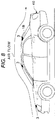
- FIG. 8 is a schematic view of a flow control apparatus according to a third example of the present invention.
- the flow control apparatus 1 B in the third example shown in FIG. 8 differs from the flow control apparatus 1 in the first example in that the control object is a flow of air around an automobile 40 .
- Other configurations and operations of the flow control apparatus 1 B in the third example are not substantially different from those of the flow control apparatus 1 in the first example, and therefore the same reference numerals are given to the same configurations or corresponding configurations, and descriptions thereof are omitted.
- the control area of the air flow is set around the automobile 40 .
- one or more plasma actuators 3 are mounted on a surface of the body and the like of the motor vehicle 40 .
- the air flow state in the air flow control area set around the automobile 40 may be changed from a first flow state to a second flow state.
- a first flow state may be formed in which delamination is suppressed, to improve fuel efficiency, by reducing air resistance during driving of the vehicle 40 , while a second flow state in which delamination is not suppressed or a second flow state in which delamination is intentionally induced to decelerate the vehicle 40 by intentionally increasing air resistance in order to stop the vehicle 40 .
- At least one of the first electrode 6 or the second electrode 7 constituting the plasma actuator 3 can be divided and arranged at different positions so that the electrode to which an AC voltage is to be applied can be selected.
- gas flow around other structures may also be the control target.
- gas flow formed by rotation of a compressor constituting a gas turbine engine or rotor blades provided in a turbine, or air flow formed by the blades constituting a turbofan for an automobile may be controlled.
- gas flow formed by the rotation of the rotor blades provided in the turbine of the gas turbine engine is the control target, the gas flow obtained by mixing the fuel gas and the air is the control target.
Landscapes
- Engineering & Computer Science (AREA)
- Physics & Mathematics (AREA)
- Aviation & Aerospace Engineering (AREA)
- Electromagnetism (AREA)
- Plasma & Fusion (AREA)
- Fluid Mechanics (AREA)
- Mechanical Engineering (AREA)
- General Engineering & Computer Science (AREA)
- Plasma Technology (AREA)
Abstract
Description
- Yoshinori Mizuno et. al., “Active Fluid Control by Multi-Electrode Microplasma Actuator,” Journal of Institute Electrostatatics Japan, 2015, Vol. 39, No. 1, p. 15-20.
- Yasuaki Kosato et al., “Controlling of Various Delamination Flows by Burst-Driven Plasma Actuators,” Fourth Symposium of the Plasma Actuator Research Society, held Mar. 18-19, 2017
- Benard et al., “On the benefits of hysteresis effects for closed-loop separation control using plasma actuation” PHYSICS OF FLUIDS 23, 083601 (2011)
- Specifically, DBD-PA, which uses a dielectric barrier discharge (DBD) to create air flow, is practical as a plasma actuator attached to an aircraft wing.
Claims (7)
Applications Claiming Priority (3)
| Application Number | Priority Date | Filing Date | Title |
|---|---|---|---|
| JP2017-249193 | 2017-12-26 | ||
| JP2017249193A JP6609302B2 (en) | 2017-12-26 | 2017-12-26 | Flow control device, flow control method, and aircraft |
| JPJP2017-249193 | 2017-12-26 |
Publications (2)
| Publication Number | Publication Date |
|---|---|
| US20190193843A1 US20190193843A1 (en) | 2019-06-27 |
| US11174007B2 true US11174007B2 (en) | 2021-11-16 |
Family
ID=66949966
Family Applications (1)
| Application Number | Title | Priority Date | Filing Date |
|---|---|---|---|
| US16/197,668 Active 2039-12-11 US11174007B2 (en) | 2017-12-26 | 2018-11-21 | Flow control apparatus, flow control method, and aircraft |
Country Status (2)
| Country | Link |
|---|---|
| US (1) | US11174007B2 (en) |
| JP (1) | JP6609302B2 (en) |
Cited By (1)
| Publication number | Priority date | Publication date | Assignee | Title |
|---|---|---|---|---|
| US20200023942A1 (en) * | 2018-07-19 | 2020-01-23 | General Electric Company | Control system for an aircraft |
Families Citing this family (18)
| Publication number | Priority date | Publication date | Assignee | Title |
|---|---|---|---|---|
| US10495121B2 (en) * | 2017-11-10 | 2019-12-03 | X Development Llc | Method and apparatus for combined anemometer and plasma actuator |
| JP7158119B2 (en) * | 2018-05-08 | 2022-10-21 | 株式会社Subaru | Aircraft steering system and aircraft |
| CN110636685B (en) * | 2019-09-10 | 2021-09-28 | 空气动力学国家重点实验室 | Wall drag reduction mechanism based on plasma generator |
| JP7412114B2 (en) * | 2019-09-18 | 2024-01-12 | 株式会社Subaru | wind tunnel test equipment |
| JP7335766B2 (en) * | 2019-09-30 | 2023-08-30 | 株式会社Subaru | rectifier |
| JP7335767B2 (en) * | 2019-09-30 | 2023-08-30 | 株式会社Subaru | rectifier |
| JP7335765B2 (en) * | 2019-09-30 | 2023-08-30 | 株式会社Subaru | rectifier |
| JP7352429B2 (en) * | 2019-09-30 | 2023-09-28 | 株式会社Subaru | Airflow separation detection method, airflow separation position detection method, airflow separation detection system, and airflow separation position detection system |
| US11939966B2 (en) | 2019-12-09 | 2024-03-26 | Electric Sky Holdings, Inc. | Plasma propulsion systems and associated systems and methods |
| JP7385526B2 (en) * | 2020-05-26 | 2023-11-22 | 株式会社Subaru | rectifier |
| JP7445525B2 (en) * | 2020-06-05 | 2024-03-07 | 日産自動車株式会社 | plasma actuator |
| JP7445526B2 (en) * | 2020-06-05 | 2024-03-07 | 日産自動車株式会社 | How to control plasma actuator |
| US20220063821A1 (en) * | 2020-08-27 | 2022-03-03 | William J. Cass | Ionic propulsion system |
| JP7590143B2 (en) | 2020-09-18 | 2024-11-26 | 株式会社Subaru | Orthosis with rectification function |
| JP7560308B2 (en) | 2020-09-30 | 2024-10-02 | 株式会社Subaru | vehicle |
| WO2024107856A1 (en) * | 2022-11-15 | 2024-05-23 | Electric Sky Holdings, Inc. | Vehicles having an e-wave for driving electric fields for acoustic wave propulsion, and associated systems and methods |
| CN115716528A (en) * | 2023-01-09 | 2023-02-28 | 中国空气动力研究与发展中心低速空气动力研究所 | Bionic leading edge wing implementation device and bionic leading edge structure establishment method |
| EP4467447A1 (en) * | 2023-05-23 | 2024-11-27 | Airbus Operations, S.L.U. | Aircraft lifting surface and aircraft comprising such lifting surface |
Citations (15)
| Publication number | Priority date | Publication date | Assignee | Title |
|---|---|---|---|---|
| JP2007317656A (en) | 2006-04-28 | 2007-12-06 | Toshiba Corp | Airflow generation device, airflow generating unit, wing, heat exchanger, micro machine, gas treatment device, airflow generating method and airflow controlling method |
| US20080023589A1 (en) * | 2006-01-03 | 2008-01-31 | Miles Richard B | Systems and methods for controlling flows with electrical pulses |
| JP2008025434A (en) | 2006-07-20 | 2008-02-07 | Toshiba Corp | Windmill blade, wind power generating system, and control method of the wind power generating system |
| JP2008290709A (en) | 2007-05-25 | 2008-12-04 | Boeing Co:The | Method of controlling flight of air movable platform and plasma actuator for affecting boundary layer flow on surface of object |
| US20090173837A1 (en) * | 2008-01-04 | 2009-07-09 | The Boeing Company | Systems and methods for controlling flows with pulsed discharges |
| US20100004799A1 (en) | 2008-07-01 | 2010-01-07 | The Boeing Company | Systems and Methods for Alleviating Aircraft Loads with Plasma Actuators |
| JP2010119946A (en) | 2008-11-19 | 2010-06-03 | Honda Motor Co Ltd | Air flow generator |
| JP2011041889A (en) | 2009-08-20 | 2011-03-03 | Toshiba Corp | Air current generator and moving assembly |
| JP2011238385A (en) | 2010-05-06 | 2011-11-24 | Tokyo Metropolitan Univ | Induced flow control surface plasma actuator |
| US8190305B1 (en) | 2003-01-03 | 2012-05-29 | Orbital Research Inc. | Hierarchical closed-loop control system for aircraft, missiles and munitions |
| US20120291874A1 (en) | 2011-05-16 | 2012-11-22 | Motofumi Tanaka | Airflow control device and airflow control method |
| JP2014175476A (en) | 2013-03-08 | 2014-09-22 | Toshiba Corp | Cooling device |
| JP2015108371A (en) | 2013-10-25 | 2015-06-11 | 株式会社東芝 | Airflow generator, mobile body, and wind power generation system |
| US20170088255A1 (en) * | 2015-09-24 | 2017-03-30 | The Boeing Company | Embedded dielectric structures for active flow control plasma sources |
| US20170297634A1 (en) * | 2016-04-15 | 2017-10-19 | GM Global Technology Operations LLC | Plasma actuator for vehicle aerodynamic drag reduction |
-
2017
- 2017-12-26 JP JP2017249193A patent/JP6609302B2/en active Active
-
2018
- 2018-11-21 US US16/197,668 patent/US11174007B2/en active Active
Patent Citations (17)
| Publication number | Priority date | Publication date | Assignee | Title |
|---|---|---|---|---|
| US8190305B1 (en) | 2003-01-03 | 2012-05-29 | Orbital Research Inc. | Hierarchical closed-loop control system for aircraft, missiles and munitions |
| US20080023589A1 (en) * | 2006-01-03 | 2008-01-31 | Miles Richard B | Systems and methods for controlling flows with electrical pulses |
| JP2007317656A (en) | 2006-04-28 | 2007-12-06 | Toshiba Corp | Airflow generation device, airflow generating unit, wing, heat exchanger, micro machine, gas treatment device, airflow generating method and airflow controlling method |
| JP2008025434A (en) | 2006-07-20 | 2008-02-07 | Toshiba Corp | Windmill blade, wind power generating system, and control method of the wind power generating system |
| JP2008290709A (en) | 2007-05-25 | 2008-12-04 | Boeing Co:The | Method of controlling flight of air movable platform and plasma actuator for affecting boundary layer flow on surface of object |
| US20100133386A1 (en) * | 2007-05-25 | 2010-06-03 | Schwimley Scott L | Plasma flow control actuator system and method |
| US20090173837A1 (en) * | 2008-01-04 | 2009-07-09 | The Boeing Company | Systems and methods for controlling flows with pulsed discharges |
| US20100004799A1 (en) | 2008-07-01 | 2010-01-07 | The Boeing Company | Systems and Methods for Alleviating Aircraft Loads with Plasma Actuators |
| JP2010119946A (en) | 2008-11-19 | 2010-06-03 | Honda Motor Co Ltd | Air flow generator |
| JP2011041889A (en) | 2009-08-20 | 2011-03-03 | Toshiba Corp | Air current generator and moving assembly |
| JP2011238385A (en) | 2010-05-06 | 2011-11-24 | Tokyo Metropolitan Univ | Induced flow control surface plasma actuator |
| US20120291874A1 (en) | 2011-05-16 | 2012-11-22 | Motofumi Tanaka | Airflow control device and airflow control method |
| JP2012241732A (en) | 2011-05-16 | 2012-12-10 | Toshiba Corp | Airflow control device, and airflow control method |
| JP2014175476A (en) | 2013-03-08 | 2014-09-22 | Toshiba Corp | Cooling device |
| JP2015108371A (en) | 2013-10-25 | 2015-06-11 | 株式会社東芝 | Airflow generator, mobile body, and wind power generation system |
| US20170088255A1 (en) * | 2015-09-24 | 2017-03-30 | The Boeing Company | Embedded dielectric structures for active flow control plasma sources |
| US20170297634A1 (en) * | 2016-04-15 | 2017-10-19 | GM Global Technology Operations LLC | Plasma actuator for vehicle aerodynamic drag reduction |
Non-Patent Citations (4)
| Title |
|---|
| Benard et al., "On the benefits of hysteresis effects for closed-loop separation control using plasma actuation" Physics of Fluids 23, 083601 (2011). |
| Notice of Reasons for Refusal dated Jul. 16, 2019 in corresponding Japanese Application No. 2017-249193. |
| Yasuaki Kosato et al., "Controlling of Various Delamination Flows by Burst-Driven Plasma Actuators," Fourth Symposium of the Plasma Actuator Research Society, held Mar. 18-19, 2017. |
| Yoshinori Mizuno et al., "Active Fluid Conlrol by Multi-Electrode Microplasma Actuator," Journal of Institute Electrostatatics Japan., 2015, vol. 39, No. 1, p. 15-20; with English abstract. |
Cited By (1)
| Publication number | Priority date | Publication date | Assignee | Title |
|---|---|---|---|---|
| US20200023942A1 (en) * | 2018-07-19 | 2020-01-23 | General Electric Company | Control system for an aircraft |
Also Published As
| Publication number | Publication date |
|---|---|
| US20190193843A1 (en) | 2019-06-27 |
| JP2019114505A (en) | 2019-07-11 |
| JP6609302B2 (en) | 2019-11-20 |
Similar Documents
| Publication | Publication Date | Title |
|---|---|---|
| US11174007B2 (en) | Flow control apparatus, flow control method, and aircraft | |
| Patel et al. | Scaling effects of an aerodynamic plasma actuator | |
| He et al. | Plasma flaps and slats: an application of weakly ionized plasma actuators | |
| Lombardi et al. | Closed-loop dynamic stall control using a plasma actuator | |
| US11214358B2 (en) | Aircraft control system, aircraft control method, and aircraft | |
| Duchmann et al. | Dielectric barrier discharge plasma actuators for in-flight transition delay | |
| Corke et al. | Plasma flow control optimized airfoil | |
| Orlov et al. | Modeling and experiment of leading edge separation control using SDBD plasma actuators | |
| Little et al. | High-lift airfoil separation with dielectric barrier discharge plasma actuation | |
| US8849603B2 (en) | Systems and methods for control system verification and health assessment | |
| He et al. | Numerical and experimental analysis of plasma flow control over a hump model | |
| US20100004799A1 (en) | Systems and Methods for Alleviating Aircraft Loads with Plasma Actuators | |
| JP7096698B2 (en) | Wing structure, wing structure control method and aircraft | |
| Das et al. | Numerical modeling of coanda effect in a novel propulsive system | |
| Zhang et al. | Numerical simulation on plasma circulation control airfoil | |
| Bauer et al. | Experiments on active drag reduction on a complex outer wing model | |
| Céspedes et al. | Simulation and validation of the aerodynamic performance of a quadcopter in hover condition using overset mesh | |
| Iranshahi et al. | Dielectric barrier discharge actuators employed as alternative to conventional high-lift devices | |
| Mystkowski | Piezo-stack vortex generators for boundary layer control of a delta wing micro-aerial vehicle | |
| Bongen et al. | Simulation of a Distributed Propulsion System in a Wind Tunnel | |
| US20190329870A1 (en) | Wing structure, method of controlling wing structure, and aircraft | |
| Boesch et al. | Flight control using wing-tip plasma actuation | |
| Lombaerts et al. | Design and flight testing of nonlinear autoflight control laws incorporating direct lift control | |
| Poggie et al. | Closed-loop stall control system | |
| Li et al. | Dynamic response of circulation control for step and sinusoidal inputs |
Legal Events
| Date | Code | Title | Description |
|---|---|---|---|
| AS | Assignment |
Owner name: SUBARU CORPORATION, JAPAN Free format text: ASSIGNMENT OF ASSIGNORS INTEREST;ASSIGNORS:KIKUCHI, MAKI;KATO, HIROKI;REEL/FRAME:047562/0085 Effective date: 20181022 |
|
| FEPP | Fee payment procedure |
Free format text: ENTITY STATUS SET TO UNDISCOUNTED (ORIGINAL EVENT CODE: BIG.); ENTITY STATUS OF PATENT OWNER: LARGE ENTITY |
|
| STPP | Information on status: patent application and granting procedure in general |
Free format text: DOCKETED NEW CASE - READY FOR EXAMINATION |
|
| STPP | Information on status: patent application and granting procedure in general |
Free format text: NON FINAL ACTION MAILED |
|
| STPP | Information on status: patent application and granting procedure in general |
Free format text: RESPONSE TO NON-FINAL OFFICE ACTION ENTERED AND FORWARDED TO EXAMINER |
|
| STPP | Information on status: patent application and granting procedure in general |
Free format text: NOTICE OF ALLOWANCE MAILED -- APPLICATION RECEIVED IN OFFICE OF PUBLICATIONS |
|
| STPP | Information on status: patent application and granting procedure in general |
Free format text: PUBLICATIONS -- ISSUE FEE PAYMENT VERIFIED |
|
| STCF | Information on status: patent grant |
Free format text: PATENTED CASE |
|
| MAFP | Maintenance fee payment |
Free format text: PAYMENT OF MAINTENANCE FEE, 4TH YEAR, LARGE ENTITY (ORIGINAL EVENT CODE: M1551); ENTITY STATUS OF PATENT OWNER: LARGE ENTITY Year of fee payment: 4 |