US11168684B2 - Variable displacement pump - Google Patents
Variable displacement pump Download PDFInfo
- Publication number
- US11168684B2 US11168684B2 US16/082,242 US201716082242A US11168684B2 US 11168684 B2 US11168684 B2 US 11168684B2 US 201716082242 A US201716082242 A US 201716082242A US 11168684 B2 US11168684 B2 US 11168684B2
- Authority
- US
- United States
- Prior art keywords
- pump
- control hydraulic
- chamber
- hydraulic chamber
- outlet
- Prior art date
- Legal status (The legal status is an assumption and is not a legal conclusion. Google has not performed a legal analysis and makes no representation as to the accuracy of the status listed.)
- Active, expires
Links
- 238000006073 displacement reaction Methods 0.000 title claims abstract description 50
- 230000007423 decrease Effects 0.000 claims abstract description 5
- 239000012530 fluid Substances 0.000 claims description 47
- 230000003247 decreasing effect Effects 0.000 claims description 14
- 238000007789 sealing Methods 0.000 abstract description 6
- 239000003921 oil Substances 0.000 description 78
- 230000004308 accommodation Effects 0.000 description 26
- 238000005086 pumping Methods 0.000 description 8
- 238000002485 combustion reaction Methods 0.000 description 7
- 230000002093 peripheral effect Effects 0.000 description 7
- 239000000356 contaminant Substances 0.000 description 5
- 239000011435 rock Substances 0.000 description 5
- 230000000452 restraining effect Effects 0.000 description 3
- 230000002159 abnormal effect Effects 0.000 description 2
- 230000000694 effects Effects 0.000 description 2
- 238000005461 lubrication Methods 0.000 description 2
- 230000013011 mating Effects 0.000 description 2
- 229910000838 Al alloy Inorganic materials 0.000 description 1
- YCKRFDGAMUMZLT-UHFFFAOYSA-N Fluorine atom Chemical compound [F] YCKRFDGAMUMZLT-UHFFFAOYSA-N 0.000 description 1
- 238000005299 abrasion Methods 0.000 description 1
- 238000005273 aeration Methods 0.000 description 1
- 229910045601 alloy Inorganic materials 0.000 description 1
- 239000000956 alloy Substances 0.000 description 1
- 230000006835 compression Effects 0.000 description 1
- 238000007906 compression Methods 0.000 description 1
- 238000001816 cooling Methods 0.000 description 1
- 238000007599 discharging Methods 0.000 description 1
- 229910052731 fluorine Inorganic materials 0.000 description 1
- 239000011737 fluorine Substances 0.000 description 1
- 239000000446 fuel Substances 0.000 description 1
- 239000010687 lubricating oil Substances 0.000 description 1
- 239000000463 material Substances 0.000 description 1
- 229910052751 metal Inorganic materials 0.000 description 1
- 239000002184 metal Substances 0.000 description 1
- 230000000149 penetrating effect Effects 0.000 description 1
- 239000000843 powder Substances 0.000 description 1
- 239000011347 resin Substances 0.000 description 1
- 229920005989 resin Polymers 0.000 description 1
- 230000008719 thickening Effects 0.000 description 1
- 238000011144 upstream manufacturing Methods 0.000 description 1
- XLYOFNOQVPJJNP-UHFFFAOYSA-N water Substances O XLYOFNOQVPJJNP-UHFFFAOYSA-N 0.000 description 1
Images


Classifications
-
- F—MECHANICAL ENGINEERING; LIGHTING; HEATING; WEAPONS; BLASTING
- F04—POSITIVE - DISPLACEMENT MACHINES FOR LIQUIDS; PUMPS FOR LIQUIDS OR ELASTIC FLUIDS
- F04C—ROTARY-PISTON, OR OSCILLATING-PISTON, POSITIVE-DISPLACEMENT MACHINES FOR LIQUIDS; ROTARY-PISTON, OR OSCILLATING-PISTON, POSITIVE-DISPLACEMENT PUMPS
- F04C2/00—Rotary-piston machines or pumps
- F04C2/30—Rotary-piston machines or pumps having the characteristics covered by two or more groups F04C2/02, F04C2/08, F04C2/22, F04C2/24 or having the characteristics covered by one of these groups together with some other type of movement between co-operating members
- F04C2/34—Rotary-piston machines or pumps having the characteristics covered by two or more groups F04C2/02, F04C2/08, F04C2/22, F04C2/24 or having the characteristics covered by one of these groups together with some other type of movement between co-operating members having the movement defined in groups F04C2/08 or F04C2/22 and relative reciprocation between the co-operating members
- F04C2/344—Rotary-piston machines or pumps having the characteristics covered by two or more groups F04C2/02, F04C2/08, F04C2/22, F04C2/24 or having the characteristics covered by one of these groups together with some other type of movement between co-operating members having the movement defined in groups F04C2/08 or F04C2/22 and relative reciprocation between the co-operating members with vanes reciprocating with respect to the inner member
-
- F—MECHANICAL ENGINEERING; LIGHTING; HEATING; WEAPONS; BLASTING
- F04—POSITIVE - DISPLACEMENT MACHINES FOR LIQUIDS; PUMPS FOR LIQUIDS OR ELASTIC FLUIDS
- F04C—ROTARY-PISTON, OR OSCILLATING-PISTON, POSITIVE-DISPLACEMENT MACHINES FOR LIQUIDS; ROTARY-PISTON, OR OSCILLATING-PISTON, POSITIVE-DISPLACEMENT PUMPS
- F04C14/00—Control of, monitoring of, or safety arrangements for, machines, pumps or pumping installations
- F04C14/18—Control of, monitoring of, or safety arrangements for, machines, pumps or pumping installations characterised by varying the volume of the working chamber
- F04C14/22—Control of, monitoring of, or safety arrangements for, machines, pumps or pumping installations characterised by varying the volume of the working chamber by changing the eccentricity between cooperating members
- F04C14/223—Control of, monitoring of, or safety arrangements for, machines, pumps or pumping installations characterised by varying the volume of the working chamber by changing the eccentricity between cooperating members using a movable cam
- F04C14/226—Control of, monitoring of, or safety arrangements for, machines, pumps or pumping installations characterised by varying the volume of the working chamber by changing the eccentricity between cooperating members using a movable cam by pivoting the cam around an eccentric axis
-
- F—MECHANICAL ENGINEERING; LIGHTING; HEATING; WEAPONS; BLASTING
- F04—POSITIVE - DISPLACEMENT MACHINES FOR LIQUIDS; PUMPS FOR LIQUIDS OR ELASTIC FLUIDS
- F04C—ROTARY-PISTON, OR OSCILLATING-PISTON, POSITIVE-DISPLACEMENT MACHINES FOR LIQUIDS; ROTARY-PISTON, OR OSCILLATING-PISTON, POSITIVE-DISPLACEMENT PUMPS
- F04C15/00—Component parts, details or accessories of machines, pumps or pumping installations, not provided for in groups F04C2/00 - F04C14/00
- F04C15/06—Arrangements for admission or discharge of the working fluid, e.g. constructional features of the inlet or outlet
-
- F—MECHANICAL ENGINEERING; LIGHTING; HEATING; WEAPONS; BLASTING
- F04—POSITIVE - DISPLACEMENT MACHINES FOR LIQUIDS; PUMPS FOR LIQUIDS OR ELASTIC FLUIDS
- F04C—ROTARY-PISTON, OR OSCILLATING-PISTON, POSITIVE-DISPLACEMENT MACHINES FOR LIQUIDS; ROTARY-PISTON, OR OSCILLATING-PISTON, POSITIVE-DISPLACEMENT PUMPS
- F04C2/00—Rotary-piston machines or pumps
- F04C2/30—Rotary-piston machines or pumps having the characteristics covered by two or more groups F04C2/02, F04C2/08, F04C2/22, F04C2/24 or having the characteristics covered by one of these groups together with some other type of movement between co-operating members
- F04C2/34—Rotary-piston machines or pumps having the characteristics covered by two or more groups F04C2/02, F04C2/08, F04C2/22, F04C2/24 or having the characteristics covered by one of these groups together with some other type of movement between co-operating members having the movement defined in groups F04C2/08 or F04C2/22 and relative reciprocation between the co-operating members
- F04C2/344—Rotary-piston machines or pumps having the characteristics covered by two or more groups F04C2/02, F04C2/08, F04C2/22, F04C2/24 or having the characteristics covered by one of these groups together with some other type of movement between co-operating members having the movement defined in groups F04C2/08 or F04C2/22 and relative reciprocation between the co-operating members with vanes reciprocating with respect to the inner member
- F04C2/3441—Rotary-piston machines or pumps having the characteristics covered by two or more groups F04C2/02, F04C2/08, F04C2/22, F04C2/24 or having the characteristics covered by one of these groups together with some other type of movement between co-operating members having the movement defined in groups F04C2/08 or F04C2/22 and relative reciprocation between the co-operating members with vanes reciprocating with respect to the inner member the inner and outer member being in contact along one line or continuous surface substantially parallel to the axis of rotation
- F04C2/3442—Rotary-piston machines or pumps having the characteristics covered by two or more groups F04C2/02, F04C2/08, F04C2/22, F04C2/24 or having the characteristics covered by one of these groups together with some other type of movement between co-operating members having the movement defined in groups F04C2/08 or F04C2/22 and relative reciprocation between the co-operating members with vanes reciprocating with respect to the inner member the inner and outer member being in contact along one line or continuous surface substantially parallel to the axis of rotation the surfaces of the inner and outer member, forming the working space, being surfaces of revolution
-
- F—MECHANICAL ENGINEERING; LIGHTING; HEATING; WEAPONS; BLASTING
- F01—MACHINES OR ENGINES IN GENERAL; ENGINE PLANTS IN GENERAL; STEAM ENGINES
- F01M—LUBRICATING OF MACHINES OR ENGINES IN GENERAL; LUBRICATING INTERNAL COMBUSTION ENGINES; CRANKCASE VENTILATING
- F01M1/00—Pressure lubrication
- F01M1/02—Pressure lubrication using lubricating pumps
- F01M2001/0207—Pressure lubrication using lubricating pumps characterised by the type of pump
- F01M2001/0238—Rotary pumps
-
- F—MECHANICAL ENGINEERING; LIGHTING; HEATING; WEAPONS; BLASTING
- F04—POSITIVE - DISPLACEMENT MACHINES FOR LIQUIDS; PUMPS FOR LIQUIDS OR ELASTIC FLUIDS
- F04C—ROTARY-PISTON, OR OSCILLATING-PISTON, POSITIVE-DISPLACEMENT MACHINES FOR LIQUIDS; ROTARY-PISTON, OR OSCILLATING-PISTON, POSITIVE-DISPLACEMENT PUMPS
- F04C15/00—Component parts, details or accessories of machines, pumps or pumping installations, not provided for in groups F04C2/00 - F04C14/00
- F04C15/0003—Sealing arrangements in rotary-piston machines or pumps
- F04C15/003—Sealings for working fluid between radially and axially moving parts
-
- F—MECHANICAL ENGINEERING; LIGHTING; HEATING; WEAPONS; BLASTING
- F04—POSITIVE - DISPLACEMENT MACHINES FOR LIQUIDS; PUMPS FOR LIQUIDS OR ELASTIC FLUIDS
- F04C—ROTARY-PISTON, OR OSCILLATING-PISTON, POSITIVE-DISPLACEMENT MACHINES FOR LIQUIDS; ROTARY-PISTON, OR OSCILLATING-PISTON, POSITIVE-DISPLACEMENT PUMPS
- F04C2210/00—Fluid
- F04C2210/20—Fluid liquid, i.e. incompressible
- F04C2210/206—Oil
-
- F—MECHANICAL ENGINEERING; LIGHTING; HEATING; WEAPONS; BLASTING
- F04—POSITIVE - DISPLACEMENT MACHINES FOR LIQUIDS; PUMPS FOR LIQUIDS OR ELASTIC FLUIDS
- F04C—ROTARY-PISTON, OR OSCILLATING-PISTON, POSITIVE-DISPLACEMENT MACHINES FOR LIQUIDS; ROTARY-PISTON, OR OSCILLATING-PISTON, POSITIVE-DISPLACEMENT PUMPS
- F04C2270/00—Control; Monitoring or safety arrangements
- F04C2270/18—Pressure
- F04C2270/185—Controlled or regulated
Definitions
- the present invention relates to a variable displacement pump applied to a hydraulic pressure source that supplies working fluid to, for instance, sliding parts in an internal combustion engine of a vehicle.
- This variable displacement pump is configured so that a first control hydraulic chamber and a second control hydraulic chamber are each defined between an inner circumferential surface of a pump housing and an outer circumferential surface of a cam ring, and further by a pump discharge pressure being supplied to the first control hydraulic chamber, the cam ring is forced in a direction (hereinafter, called a concentric direction) in which an eccentric amount of the cam ring becomes small, while by the pump discharge pressure being supplied to the second control hydraulic chamber, the cam ring is forced in a direction (hereinafter, called an eccentric direction) in which the eccentric amount of the cam ring becomes large. Further, a coil spring forces the cam ring so as to increase the eccentric amount in the eccentric direction by a spring force of the coil spring in cooperation with the working fluid in the second control hydraulic chamber.
- each internal pressure of a plurality of pump chambers that are defined by a plurality of vanes extending and retracting from an outer circumferential surface of a rotor in a radial direction and an inner circumferential surface of the cam ring also contributes to a rocking control (or a movement control) of the cam ring in eccentric/concentric directions.
- the eccentric amount of the cam ring is controlled in accordance with an engine rotation speed, and by controlling a required discharge pressure at two levels of low and high pressure characteristics, supply of oil to a plurality of devices can be possible.
- the plurality of pump chambers and the first and second control hydraulic chambers are sealed by so-called side clearance between opposing inside surfaces of the pump housing and both axial direction end surfaces, which are in sliding-contact with the respective opposing inside surfaces of the pump housing, of the cam ring.
- the second control hydraulic chamber is located at a discharge side area that is a high pressure area of each pump chamber, for instance, in a case where a viscosity of oil is low, e.g. when temperature of the oil (the working fluid) is high, a sealing performance by the side clearance is inadequate, and there is a risk that a high pressure oil in each pump chamber will leak into the second control hydraulic chamber through the side clearance. That is, rapid or smooth discharge of the oil from the second control hydraulic chamber becomes impossible due to passage resistances of the electromagnetic switching valve and the pilot valve at times when performing a low pressure control and a high pressure control, then a leak amount of the oil flowing into the second control hydraulic chamber through the side clearance becomes relatively large.
- the present invention was made in view of the above technical problem of the related-art variable displacement pump.
- An object of the present invention is therefore to provide a variable displacement pump that is capable of suppressing the increase in weight of the whole of the pump while suppressing the increase in the pump control pressure against the intention of the control.
- a variable displacement pump of the present invention comprises: a rotor that is driven and rotates; a plurality of vanes that are provided at an outer circumferential portion of the rotor so as to be able to extend and retract; a ring-shaped movable member that defines a plurality of working fluid chambers by accommodating the rotor and the plurality of vanes at an inner circumferential side of the movable member and changes a volume variation of each working fluid chamber during rotation of the rotor by moving so that an inner circumferential center of the movable member changes with respect to a rotation center of the rotor; a pump housing that houses therein the rotor, the vanes and the movable member, both axial direction end surfaces of the movable member being in sliding-contact with both opposing inside surfaces of the pump housing; an inlet section that is formed on at least one of the both inside surfaces of the pump housing and opens in an inlet-side area where a volume of each working fluid chamber is increased by the rotation of the rotor; an outlet section that
- FIG. 1 is a front view of a variable displacement pump according to a first embodiment of the present invention with a cover member removed.
- FIG. 2 is a sectional view taken along an A-A line of FIG. 1 .
- FIG. 3 is a drawing showing a pump body of the present embodiment, viewed from a mating surface side with the cover member.
- FIG. 4 is a drawing showing the cover member of the present embodiment, viewed from a mating surface side with the pump body.
- FIG. 5 is a drawing for explaining working of the variable displacement pump in a state in which an eccentric amount of a cam ring is decreased.
- FIG. 6 is a graph showing a hydraulic pressure characteristic of the variable displacement pump of the present embodiment.
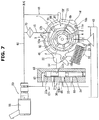
- FIG. 7 is a schematic view of a variable displacement pump according to a second embodiment.
- FIG. 8 is a schematic view of a variable displacement pump according to a third embodiment.
- variable displacement pump of the present invention
- VTC valve timing control device
- variable displacement pump is provided at a front end portion of a cylinder block (not shown) of an internal combustion engine (not shown).
- the variable displacement pump has a pump housing formed by a pump body 1 which has a square bracket in a longitudinal cross section, whose one end side is open and which has therein a pump accommodation chamber 3 and a cover member 2 which covers the one end opening of the pump body 1 , a drive shaft 4 that is rotatably supported by the pump housing with the drive shaft 4 penetrating a substantially middle of the pump accommodation chamber 3 and that is driven and rotates by a crankshaft (not shown) of the engine (not shown), a cam ring 5 that is movably (rockably) accommodated in the pump accommodation chamber 3 and changes a volume variation of each pump chamber 13 in cooperation with after-mentioned first and second control hydraulic chambers 21 and 22 and coil spring 23 , and a pump configuration unit that is accommodated at an inner circumferential side of the cam ring 5 , increases and decreases
- a pump cover (the cover member 2 ) is provided with a pilot valve 30 that is a control mechanism that performs a supply/discharge control of a hydraulic pressure to and from the second control hydraulic chamber 22 and an interrupting control of the oil supply.
- a solenoid valve 50 as a switching mechanism that performs a switching control of introduction of oil that is a discharged working fluid to the pilot valve 30 side is provided on an after-mentioned control pressure introduction passage 60 formed between the pilot valve 30 and an after-mentioned discharge passage 18 .
- the pump configuration unit is formed by a rotor 6 which is rotatably accommodated at the inner circumferential side of the cam ring 5 and whose middle portion is secured to an outer circumference of the drive shaft 4 , a plurality of vanes 7 that are accommodated so as to be able to extend/retract in a plurality of slits 6 a formed at an outer circumferential portion of the rotor 6 by being cut in a radial direction, and a pair of ring members 8 , 8 that have a smaller diameter than that of the rotor 6 and are provided at inner circumferential side both side portions of the rotor 6 .
- the pump body 1 is formed as a single-piece body with aluminum alloy. As shown in FIG. 1 to 3 , the pump body 1 is shaped into a rectangle that extends in up-and-down directions, and a width of the pump body 1 is smaller than a length in the up-and-down directions of the pump body 1 .
- the pump body 1 is provided, at a substantially middle position on an end wall 1 a forming a bottom surface of the pump accommodation chamber 3 , with a bearing hole 1 b that rotatably supports one end portion 4 a of the drive shaft 4 .
- a first seal sliding contact surface 1 d with which a first seal member 10 a provided at an outer circumferential portion of the cam ring 5 is in sliding-contact is formed.
- This first seal sliding contact surface 1 d is formed into an arc surface shape formed with a predetermined radius R 1 being separated from a center of the supporting groove 1 c .
- a circumferential direction length of the first seal sliding contact surface 1 d is set such that the first seal member 10 a can always be in sliding-contact with the first seal sliding contact surface 1 d within an eccentric rocking range of the cam ring 5 .
- a second seal sliding contact surface 1 e with which a second seal member 10 b provided at the outer circumferential portion of the cam ring 5 is in sliding-contact is formed.
- This second seal sliding contact surface 1 e is formed into an arc surface shape formed with a predetermined radius R 2 being separated from the center of the supporting groove 1 c .
- a circumferential direction length of the second seal sliding contact surface 1 e is set such that the second seal member 10 b can always be in sliding-contact with the second seal sliding contact surface 1 e within the eccentric rocking range of the cam ring 5 .
- An arc hollow groove 40 that forms an after-mentioned low pressure chamber 41 is formed between the supporting groove 1 c on the inner circumferential surface of the pump accommodation chamber 3 and the first control hydraulic chamber 21 defined by the first seal sliding contact surface 1 d .
- a third seal sliding contact surface 1 f with which a third seal member 10 c provided at the outer circumferential portion of the cam ring 5 is in sliding-contact is formed on an inside surface at the first control hydraulic chamber 21 side of the hollow groove 40 .
- This third seal sliding contact surface 1 f is formed into an arc surface shape formed with a predetermined radius R 3 being separated from the center of the supporting groove 1 c .
- a circumferential direction length of the third seal sliding contact surface 1 f is set such that the third seal member 10 c can always be in sliding-contact with the third seal sliding contact surface 1 f within the eccentric rocking range of the cam ring 5 .
- the hollow groove 40 is formed, as shown in FIGS. 1 and 3 , at a left side of the pivot pin 9 in the drawings.
- the hollow groove 40 as a whole is shaped into an arc shape that extends in an up-and-down longitudinal direction on an inner circumferential surface of the pump body 1 .
- a substantially arc-shaped recessed inlet port 11 a as an inlet section that is open in an area (hereinafter, called an inlet-side area) where the volume of each pump chamber 13 is increased by and according to a pumping operation of the pump configuration unit is formed at an outer circumferential area of the bearing hole 1 b .
- a substantially arc-shaped recessed outlet port 12 a as an outlet section that is open in an area (hereinafter, called an outlet-side area) where the volume of each pump chamber 13 is decreased by and according to the pumping operation of the pump configuration unit is formed at the outer circumferential area of the bearing hole 1 b .
- These inlet port 11 a and outlet port 12 a are formed by being cut, and arranged at substantially opposite sides of the bearing hole 1 b at upper and lower sides of the bearing hole 1 b.
- the outlet-side area of the present embodiment As the outlet-side area of the present embodiment, as shown in FIG. 1 , it is formed from a start end S up to a termination end F of the outlet port 12 a in a rotation direction of the drive shaft 4 (the rotor 6 ).
- the inlet port 11 a has, at a substantially middle position in a circumferential direction thereof, an introduction portion 11 b that is formed as an integral part of the inlet port 11 a so as to extend to an after-mentioned spring accommodation chamber 16 side. Further, the inlet port 11 a has, at a position close to a boundary between this introduction portion 11 b and the inlet port 11 a , an inlet hole 11 c that penetrates the end wall 1 a of the pump body 1 and opens to an external portion. Therefore, oil stored in an oil pan 43 is sucked into each pump chamber 13 in the inlet-side area by a negative pressure generated according to the pumping operation by the pump configuration unit through the inlet hole 11 c and the inlet port 11 a.
- the outlet port 12 a has, at a termination end F side thereof, an outlet hole 12 b that penetrates the end wall 1 a of the pump body 1 and opens to the external portion. Therefore, as shown in FIG. 1 , oil pressurized by the pumping operation and discharged to the outlet port 12 a is supplied to the sliding parts in the internal combustion engine and the VTC etc. from the outlet hole 12 b through the discharge passage 18 formed inside the cylinder block (not shown) and a main oil gallery (not shown). At a downstream side of the discharge passage 18 , an oil cooler and an oil filter 70 are provided.
- a communication groove 15 that connects the outlet port 12 a and the bearing hole 1 b is formed at the outlet port 12 a by being cut.
- the oil is supplied to the bearing hole 1 b from this communication groove 15 , and also the oil is supplied to the rotor 6 and a side portion of each vane 7 , thereby securing good lubrication of each sliding part.
- the cover member 2 has a plate shape, as shown in FIGS. 2 and 4 .
- the cover member 2 is shaped into a rectangle that extends in the up-and-down directions so as to be fitted to an outside shape of the pump body 1 .
- An outer circumferential side of an inside surface 2 b of the cover member 2 is fixed to a fixing surface 1 g , on an opening side of the pump accommodation chamber 3 , of the pump body 1 with a plurality of bolts (not shown).
- the cover member 2 is provided, at a position corresponding to the bearing hole 1 b of the pump body 1 , with a bearing hole 2 a that rotatably supports a large diameter other end portion 4 b of the drive shaft 4 .
- an inlet port 11 a ′, an outlet port 12 a ′ and a communication groove 15 ′ are formed at the respective opposing sides to the inlet port 11 a , the outlet port 12 a and the communication groove 15 of the pump body 1 .
- the inlet port and the outlet port could be formed at either one of the pump body 1 side or the cover member 2 side.
- the small diameter one end portion 4 a of the drive shaft 4 is supported by the bearing hole 1 b formed at the end wall 1 a of the pump body 1 .
- the large diameter other end portion 4 b of the drive shaft 4 is supported by the bearing hole 2 a of the cover member 2 , and a top end side of the large diameter other end portion 4 b protrudes to the outside and is linked to the crankshaft etc.
- the drive shaft 4 rotates the rotor 6 in the clockwise direction (in an arrow direction) in FIG. 1 by a rotation force transmitted from the crankshaft.
- the rotor 6 has a plurality of slits 6 a formed in a radial direction from a center side to a radial direction outer side. Further, a back pressure chamber 6 b which has a substantially circular shape in cross section and into which the discharged oil as the working fluid is introduced is formed at an inner side base end portion of each slit 6 a . Therefore, each vane 7 is pushed out outwards by centrifugal force generated by rotation of the rotor 6 and a hydraulic pressure of the back pressure chamber 6 b.
- each vane 7 is in sliding-contact with an inner circumferential surface of the cam ring 5 during rotation of the rotor 6
- a base end surface of each vane 7 is in sliding-contact with an outer circumferential surface of each of the ring members 8 , 8 during rotation of the rotor 6 .
- the cam ring 5 is formed, as a single-piece component, into a substantially cylindrical shape with so-called sintered alloy.
- the cam ring 5 has, at a predetermined position of an outer circumferential portion thereof, a substantially arc-shaped recessed grooved pivot portion 5 a that is formed along an axial direction of the cam ring 5 and fitted onto the pivot pin 9 .
- the cam ring 5 has, at a position opposite to this pivot portion 5 a , an arm portion 5 b that protrudes in the radial direction and contacts or is connected to the after-mentioned coil spring 23 as a forcing member which is set to a predetermined spring constant.
- a spring accommodation chamber 16 is formed at a position opposite to the supporting groove 1 c .
- the coil spring 23 that is given a predetermined set load K is elastically installed between one end wall of the spring accommodation chamber 16 and one side surface of the arm portion 5 b in the spring accommodation chamber 16 .
- the other end wall of the spring accommodation chamber 16 serves as a restraining surface 16 a that restrains the moving range (or the rocking range) in an eccentric direction of the cam ring 5 . That is, by contact of the other side surface of the arm portion 5 b with this restraining surface 16 a , the movement (the rock) in the eccentric direction of the cam ring 5 is restrained to their contact position.
- the cam ring 5 is always forced in a direction (in the clockwise direction in FIG. 1 ) in which an eccentric amount of the cam ring 5 is increased by an urging force of the coil spring 23 through the arm portion 5 b . That is, in a non-operation state, as shown in FIG. 1 , the other side surface of the arm portion 5 b is pressed against the restraining surface 16 a , and the cam ring 5 is limited to a position at which the eccentric amount of the cam ring 5 is a maximum.
- first, second and third seal configuration portions 5 c , 5 d and 5 e which are concentric with the respective first, second and third seal sliding contact surfaces 1 d , 1 e and 1 f formed by an inner circumferential wall of the pump body 1 , are formed at positions facing to the respective first, second and third seal sliding contact surfaces 1 d , 1 e and 1 f so as to protrude from the outer circumferential portion of the cam ring 5 .
- the first, second and third seal members 10 a , 10 b and 10 c which are in sliding-contact with the first, second and third seal sliding contact surfaces 1 d , 1 e and 1 f respectively upon eccentric rocking of the cam ring 5 , are accommodated and held in seal holding grooves formed at seal surfaces of the seal configuration portions 5 c , 5 d and 5 e respectively.
- Each of the first, second and third seal members 10 a , 10 b and 10 c is made of fluorine resin material having a low friction property, and has a long narrow straight shape along the axial direction of the cam ring 5 .
- the first, second and third seal members 10 a , 10 b and 10 c are pressed against the first, second and third seal sliding contact surfaces 1 d , 1 e and 1 f respectively by elastic forces of elastic members that are made of rubber and provided at bottoms of the respective seal holding grooves, thereby liquid-tightly sealing gaps between the seal sliding contact surfaces 1 d , 1 e and 1 f and the seal surfaces of the seal configuration portions 5 c , 5 d and 5 e.
- the first control hydraulic chamber 21 , the second control hydraulic chamber 22 and the low pressure chamber 41 are formed at right and left positions in a circumferential direction with the pivot pin 9 being a center.
- first control hydraulic chamber 21 is defined between the first seal member 10 a and the third seal member 10 c .
- the second control hydraulic chamber 22 is defined between the pivot pin 9 and the second seal member 10 b .
- the low pressure chamber 41 is defined between the pivot pin 9 and the third seal member 10 c.
- a first pressure receiving surface 5 f which faces to the first control hydraulic chamber 21 , of the outer circumferential surface of the cam ring 5 is formed to be smaller due to the presence of the low pressure chamber 41 defined between the pivot pin 9 and the third seal member 10 c , while a second pressure receiving surface 5 g which greatly extends from the pivot pin 9 in the circumferential direction and faces to the second control hydraulic chamber 22 is formed to be larger.
- the first and second control hydraulic chambers 21 and 22 are configured so that the pump discharge pressure is introduced into the first and second control hydraulic chambers 21 and 22 through the control pressure introduction passage 60 that branches off from the discharge passage 18 . That is, the first control hydraulic chamber 21 is supplied with the pump discharge pressure through a first introduction passage 61 that is one side of a bifurcated passage further branching off from the control pressure introduction passage 60 . On the other hand, the second control hydraulic chamber 22 is supplied with the pump discharge pressure from a second introduction passage 62 that is the other side of the bifurcated passage through the electromagnetic switching valve 50 and the pilot valve 30 . These hydraulic pressures act on the first and second pressure receiving surface 5 f and 5 g of the cam ring 5 which face to the first and second control hydraulic chambers 21 and 22 respectively, then a moving force (a rocking force) is given to the cam ring 5 .
- the low pressure chamber 41 is formed along the up-and-down directions of the pump body 1 by the hollow groove 40 , as shown in FIGS. 1 to 3 .
- the low pressure chamber 41 opens to the atmospheric air outside the pump and also communicates with the oil pan 43 through a communication hole 42 formed at the cover member 2 so as to penetrate the cover member 2 . That is, as described later, oil leaking out from sliding contact surfaces (side clearances) between both axial direction end surfaces 5 h and 5 i of the cam ring 5 , the pump body 1 and the cover member 2 and so-called contaminant getting into the oil flow into the low pressure chamber 41 by the pumping operation.
- the low pressure chamber 41 is configured to discharge these oil and contaminant to the oil pan 43 through the communication hole 42 .
- the communication hole 42 is located at a position close to the pivot pin 9 on a gravitational direction lower side in the low pressure chamber 41 .
- the communication hole 42 is formed substantially horizontally by a long narrow hole having a small diameter which penetrates a wall portion of the cover member 2 .
- One end portion 42 a of the communication hole 42 opens at a bottom side of the low pressure chamber 41 .
- the other end portion 42 b of the communication hole 42 opens at an outside surface of the cover member 2 , and extends or is connected to the oil pan 43 .
- the one end portion 42 a of the communication hole 42 is provided at a position that always secures communication between the low pressure chamber 41 and the oil pan 43 by the communication hole 42 at any rocking position of the cam ring 5 without being closed by the cam ring 5 .
- gaps or boundaries between the first and second control hydraulic chambers 21 and 22 and each pump chamber 13 are sealed by so-called side clearances formed between a bottom surface 3 a , which is in sliding-contact with the axial direction end surface 5 i of the cam ring 5 , of an inside surface of the pump accommodation chamber 3 at the pump body 1 side and this axial direction end surface 5 i of the cam ring 5 and between the inside surface 2 b , which is in sliding-contact with the axial direction end surface 5 h of the cam ring 5 , of the cover member 2 and this axial direction end surface 5 h of the cam ring 5 .
- Gaps or boundaries between the low pressure chamber 41 and each pump chamber 13 are also sealed by the side clearances between the both axial direction end surfaces 5 h and 5 i of the cam ring 5 , the bottom surface 3 a of the pump accommodation chamber 3 and the inside surface 2 b of the cover member 2 .
- a section, which seals the gaps or the boundaries between the first control hydraulic chamber 21 and each pump chamber 13 , of the both axial direction end surfaces 5 h and 5 i of the cam ring 5 which form the side clearances is called a first seal surface 44 as a first seal part.
- a section, which seals the gaps or the boundaries between the second control hydraulic chamber 22 and each pump chamber 13 , of the both axial direction end surfaces 5 h and 5 i of the cam ring 5 is called a second seal surface 45 as a second seal part.
- a section, which seals the gaps or the boundaries between the low pressure chamber 41 located at the outlet-side area and each pump chamber 13 , of the both axial direction end surfaces 5 h and 5 i of the cam ring 5 is called a third seal surface 46 as a third seal part.
- the first to third seal parts 44 to 46 are formed on the both axial direction end surfaces 5 h and 5 i of the cam ring 5 , in the flowing description, for the sake of convenience, only one end surface 5 h side, which is shown in FIG. 1 , will be explained.
- the second and third second seal surfaces 45 and 46 are formed so that a width W 2 in the radial direction of the second seal surface 45 and a width W 2 in the radial direction of the third seal surface 46 are substantially the same as each other. Further, this radial direction width W 2 is greater than a radial direction width W 1 of the first seal surface 44 .
- the pump chambers 13 at the first control hydraulic chamber 21 side are located in the inlet-side area with which the inlet ports 11 a and 11 a ′ communicate, and the pump chambers 13 in this inlet-side area are in a negative pressure (low pressure) state. Because of this, a hydraulic pressure acting on the first seal surface 44 is a low pressure.
- the pump chambers 13 at the second control hydraulic chamber 22 side and the low pressure chamber 41 side are located in the outlet-side area (from the start ends up to the termination end F of the outlet ports 12 a and 12 a ′) with which the outlet ports 12 a and 12 a ′ communicate, and the pump chambers 13 in this outlet-side area are in a positive pressure (high pressure) state. Because of this, a hydraulic pressure acting on the second seal surface 45 and the third seal surface 46 is a high pressure.
- each of seal areas of the second and third second seal surfaces 45 and 46 which are formed by a relative connection with the bottom surface 3 a of the pump accommodation chamber 3 , is larger than a seal area of the first seal surface 44 .
- an average radial direction width W 1 of the first seal surface 44 is set to about 3.5 mm, whereas an average radial direction width W 2 of the second and third second seal surfaces 45 and 46 is set to about 5.0 mm that is greater than the average radial direction width W 1 .
- the pilot valve 30 is provided at an upper end portion located in a longitudinal direction of the cover member 2 of the pump body 1 as an overlap portion with the cover member 2 , and is arranged along a transverse direction.
- the pilot valve 30 is formed mainly by a cylindrical valve body 31 that extends to an outer side of the cover member 2 , a plug 32 that closes a bottom opening of the valve body 31 , a spool valve body 33 that is slidably accommodated in a valve accommodation hole 31 a formed in the valve body 31 along an axial direction of the valve body 31 and controls supply and discharge of the hydraulic pressure to and from the second control hydraulic chamber 22 by a pair of first and second land portions 33 a and 33 b that are in sliding-contact with an inner circumferential surface of the valve body 31 , and a valve spring 34 that is elastically installed between the plug 32 and the spool valve body 33 at other end side inner circumferential side of the valve body 31 with a predetermined set load given to the valve spring 34 and always forces the spool valve body 33 to one end side of the valve body 31 .
- a passage is formed at an axial direction middle position between the valve body 31 and the pump body 1 , and its one end side is connected to the second control hydraulic chamber 22 , and its other end side is always connected to an after-mentioned intermediate chamber 31 b .
- a supply/discharge port 64 that supplies and discharges the hydraulic pressure to and from the second control hydraulic chamber 22 is formed.
- a first drain port 65 one end side of which directly opens to the outside or is connected to the inlet side, and the other end side of which discharges the hydraulic pressure from the second control hydraulic chamber 22 through the intermediate chamber 31 b by switching a connection with this intermediate chamber 31 b , is formed at a substantially middle position in an axial direction of a peripheral wall of the valve body 31 . Also at the axial direction position of the valve body 31 which is an overlap portion with an after-mentioned back pressure chamber, in the same manner as the first drain port 65 , a second drain port 66 that directly opens to the outside or is connected to the inlet side is formed.
- a communication oil passage 67 that communicates with the valve body 31 in a state in which the spool valve body 33 is positioned at a left end side position in FIG. 1 in cooperation with the pump body 1 is formed at the peripheral wall of the valve body 31 .
- the spool valve body 33 has a small diameter shaft portion 33 c formed between the first and second land portions 33 a and 33 b that are both end portions in the axial direction.
- the spool valve body 33 is provided with a pressure chamber 68 which is formed at an axial direction outer end side of the first land portion 33 a in the valve body 31 and into which the discharge pressure from the introduction port 63 is introduced, the intermediate chamber 31 b that is formed at an outer periphery of the small diameter shaft portion 33 c and connects the supply/discharge port 64 and the communication oil passage 67 or connects the supply/discharge port 64 and the first drain port 65 according to an axial direction position of the spool valve body 33 , and the back pressure chamber that is formed between the second land portion 33 b and the plug 32 and serves to discharge oil leaking out from the intermediate chamber 31 b through an outer peripheral side (a slight gap) of the second land portion 33 b.
- the spool valve body 33 is positioned at the one end side of the valve accommodation hole 31 a by an urging force of the valve spring 34 (see FIG. 1 ).
- the communication oil passage 67 communicates with the intermediate chamber 31 b and the intermediate chamber 31 b communicates with the second control hydraulic chamber 22 through the supply/discharge port 64 , whereas communication between the first drain port 65 and the intermediate chamber 31 b is interrupted by the second land portion 33 b .
- the hydraulic pressure introduced from the downstream side passage 62 a through the communication oil passage 67 is supplied to the second control hydraulic chamber 22 through the intermediate chamber 31 b and the supply/discharge port 64 .
- both of the communication oil passage 67 and the first drain port 65 communicate with the supply/discharge port 64 for a short time, or communications of the both with the supply/discharge port 64 are interrupted for a short time.
- the solenoid valve 50 is accommodated in a valve accommodation hole (not shown) that is formed at some midpoint of the control pressure introduction passage 60 .
- the solenoid valve 50 is formed mainly by a cylindrical valve body 51 having therein an oil passage 54 formed along an axial direction of the cylindrical valve body 51 , a seat member 52 fixed to a top end side inner portion of the oil passage 54 and having an introduction port 55 that is connected to an upstream side of the second introduction passage 62 , a ball valve body 53 provided so as to be able to be seated on and separate from a valve seat that is formed at an inner end opening edge of the seat member 52 and serving to open and close the introduction port 55 , and a solenoid 56 provided at other end portion of the valve body 51 .
- the valve body 51 also has, at an inner end opening edge of a valve body accommodation port 57 that accommodates therein the ball valve body 53 , the same valve seat as the valve seat of the seat member 52 . Further, the valve body 51 has, at an outer peripheral portion of the valve body accommodation port 57 on one end side of a peripheral wall thereof, a supply/discharge port 58 that is formed in a radial direction and is connected to the downstream side passage 62 a for supplying and discharging the hydraulic pressure to and from the pilot valve 30 . In addition, the valve body 51 has, at an outer peripheral portion of the oil passage 54 on the other end side of the peripheral wall thereof, a drain port 59 that is formed along the radial direction and communicates with the oil pan 43 .
- the solenoid 56 is configured so that when a coil accommodated in a casing is energized (the coil is fed with a current), an armature arranged at an inner circumferential side of the coil and a rod 56 a fixed to this armature move forward in a lower side in FIG. 1 by an electromagnetic force generated by the energization.
- the solenoid 56 is fed with an exciting current from a vehicle-mounted ECU (not shown) in accordance with an engine operating condition detected or calculated by an oil temperature and a water temperature of the internal combustion engine and a predetermined parameter such as an engine rotation speed.
- P 1 in the drawing denotes an engine required pressure that corresponds to a required pressure for the VTC that is capable of improving fuel efficiency.
- P 2 denotes an engine required pressure that corresponds to a required pressure for an oil jet for cooling a piston and an engine required pressure for lubrication of bearing parts of the crankshaft at a time when the engine rotation speed is high.
- a connecting line formed by connecting these points P 1 and P 2 by a solid line denotes an ideal necessary pressure (a discharge pressure) P according to the engine rotation speed.
- Pc in the drawing denotes a cam ring operating pressure at which the cam ring 5 starts to move in the concentric direction against the urging force of the coil spring 23 having the set load K.
- Ps denotes a spool operating pressure at which the spool valve body 33 starts to move from the one end side to the other end side of the valve body 31 against the urging force of the valve spring 34 having a set load K 1 and the first drain port 65 start to open.
- the oil in the second control hydraulic chamber 22 is discharged to the oil pan 43 from the drain port 59 of the solenoid valve 50 through the downstream side passage 62 a and the oil passage 54 , and the discharge pressure P is supplied only to the first control hydraulic chamber 21 .
- This rotation range is in a state in which the discharge pressure (an engine inside pressure) P is lower than the cam ring operating pressure Pc. Because of this, the cam ring 5 is maintained at the maximum eccentric state. And, as characteristics of the discharge pressure P, the discharge pressure P increases substantially in proportion to the engine rotation speed.
- the spool valve body 33 of the pilot valve 30 is positioned at the one end side of the valve body 31 (a position shown in FIG. 1 ), and the communication oil passage 67 and the supply/discharge port 64 communicate with each other through the intermediate chamber 31 b .
- the discharge pressure P is therefore supplied to the second control hydraulic chamber 22 .
- an urging force in the eccentric direction which is formed by a total force of the urging force of the coil spring 23 and the urging force based on the internal pressure of the second control hydraulic chamber 22 exceeds the urging force in the concentric direction which is based on the internal pressure of the first control hydraulic chamber 21 . Because of this, the cam ring 5 is pressed back (or pushed back) to the eccentric direction, and the increase amount of the discharge pressure P becomes large (increases) again, then a high pressure characteristic appears (a section “c” in FIG. 6 ).
- the discharge pressure P increases according to this pressure increase characteristic and reaches the spool operating pressure Ps
- the discharge pressure P is introduced into the pressure chamber 68 from the introduction port 63 by the pilot valve 30 .
- the spool valve body 33 moves to the plug 32 side by this discharge pressure against the urging force of the valve spring 34 , and the position of the spool valve body 33 is changed from the one end side to the other end side of the valve body 31 .
- the oil pump is configured so that by the spool valve body 33 of the pilot valve 30 , the communication between the supply/discharge port 64 communicating with the second control hydraulic chamber 22 and the communication oil passage 67 and the communication between the supply/discharge port 64 communicating with the second control hydraulic chamber 22 and the first drain port 65 are changed continuously and alternately, then the discharge pressure P is controlled to be maintained at the spool operating pressure Ps.
- the oil pump of the present embodiment can maintain the discharge pressure P at this high pressure by a pressure control by the pilot valve 30 .
- the radial direction width W 2 of the second and third second seal surfaces 45 and 46 of the cam ring 5 is set to be greater than the radial direction width W 1 of the first seal surface 44 . Therefore, for instance, even in a case where a viscosity of oil is low during the pumping operation, e.g. even when temperature of the oil (the working fluid) is high during the pumping operation, the second and third second seal surfaces 45 and 46 each have an adequate sealing performance. It is thus possible to properly suppress leak of high pressure oil in each pump chamber 13 in the outlet-side area to the second control hydraulic chamber 22 and the low pressure chamber 41 .
- a radial direction width (a radial direction thickness) of the cam ring 5 as a whole is not thickened, but only the radial direction widths W 2 of the second and third second seal surfaces 45 and 46 are partly thickened. Therefore, since the radial direction width W 1 of the first seal surface 44 which is in the low pressure inlet-side area is relatively thin, an increase in weight of the cam ring 5 can be suppressed, and consequently this can suppress an increase in weight of the whole of the pump.
- the first pressure receiving surface 5 f of the cam ring 5 which is positioned at the first control hydraulic chamber 21 , is relatively smaller, and a pressure receiving area of the second pressure receiving surface 5 g positioned at the second control hydraulic chamber 22 is larger than a pressure receiving area of this first pressure receiving surface 5 f . Because of this, it is possible to suppress an unstable behavior of the cam ring 5 which occurs due to air bubble getting into the oil caused by, for instance, aeration or cavitation in each pump chamber 13 in the high pressure state (P 2 in FIG. 6 ) of the discharge pressure.
- the high pressure oil in each pump chamber 13 might pass through the third seal surface 46 and this oil and contaminant, such as metal powder, getting into this oil flow into the low pressure chamber 41 and are temporarily collected in the low pressure chamber 41 .
- these are efficiently discharged from the low pressure chamber 41 to the oil pan 43 through the communication hole 42 . Therefore, an abnormal abrasion (or an abnormal wear) of each component or element of the pump configuration unit in the pump chamber 13 , which occurs due to the contaminant etc., can be suppressed, and this brings about increase in durability of the pump.
- FIG. 7 shows a second embodiment.
- arrangement of the oil pump is reversed with respect to the first embodiment, and the rotation direction of the drive shaft 4 is a counterclockwise direction (in an arrow direction) in the drawing. Further, the low pressure chamber 41 in the first embodiment is removed. Since a basic structure or configuration of the second embodiment is the same as that of the first embodiment, the same element or component as that of the first embodiment is denoted by the same reference sign, and its explanation will be omitted.
- the cam ring 5 is arranged in a right-and-left-reverse direction with respect to the first embodiment, and the first control hydraulic chamber 21 is located at a right side in the drawing, whereas the second control hydraulic chamber 22 is located at a left side in the drawing.
- the inlet port 11 a is located at a lower side in the drawing, and a part of the inlet port 11 a overlaps the first control hydraulic chamber 21 in a radial direction.
- the outlet port 12 a is located at an upper side in the drawing, and a large part of the outlet port 12 a overlaps the second control hydraulic chamber 22 in the radial direction.
- the outlet-side area it is formed from a start end S up to a termination end F of the outlet port 12 a in the rotation direction of the drive shaft 4 . And, gaps or boundaries between each pump chamber 13 and the second control hydraulic chamber 22 in this area are sealed by the second seal surface 45 .
- FIG. 8 shows a third embodiment.
- both of the first control hydraulic chamber 21 and the second control hydraulic chamber 22 are located on a right side of the pivot pin 9 , and an oil chamber arranged on a left side of the pivot pin 9 is a low pressure chamber that communicates with the inlet port 11 a .
- the pilot valve in the above embodiments is removed.
- a supply/discharge control of the pump discharge pressure is carried out such that the second control hydraulic chamber 22 is supplied with the discharge pressure from the downstream side passage 62 a of the second introduction passage 62 branching off from the discharge passage 18 only through the electromagnetic switching valve 50 .
- the pump discharge pressure supplied to the second control hydraulic chamber 22 moves or rocks the cam ring 5 in a clockwise direction in the drawing, i.e. in the concentric direction, against a spring force of the coil spring 23 in cooperation with a pump discharge pressure of the first control hydraulic chamber 21 .
- the first control hydraulic chamber 21 is supplied with the pump discharge pressure from the first introduction passage 61 , in the same manner as the above embodiments. Further, each pump chamber 13 positioned at an inner side with respect to the first control hydraulic chamber 21 through the cam ring 5 communicates with the outlet port 12 a . Therefore, a high pressure at an early stage of compression by the pump configuration unit and the pump discharge pressure in the first control hydraulic chamber 21 , which are almost equal to each other, act on inside and outside surfaces of the cam ring 5 , positioned at this portion (at the inner side with respect to the first control hydraulic chamber 21 ), respectively.
- a radial direction width W 1 , between the first control hydraulic chamber 21 and each pump chamber 13 positioned at the inner side with respect to the first control hydraulic chamber 21 , of the cam ring 5 is formed to be sufficiently small. That is, since the hydraulic pressures, which are almost equal to each other, act on the inside and outside surfaces of this portion of the cam ring 5 , even though the radial direction width W 1 of the first seal surface 44 is small, there is almost no leak of the oil from each pump chamber 13 to the first control hydraulic chamber 21 .
- the drive shaft 4 rotates in the counterclockwise direction (in an arrow direction) in the drawing, in the same manner as the second embodiment.
- the outlet-side area it is formed from a termination end F′ of the inlet port 11 a ′ up to a start end S of the outlet port 12 a .
- a radial direction width W 2 of the second seal surface 45 of the cam ring 5 in this outlet-side area is formed to be sufficiently greater than the radial direction width W 1 of the first seal surface 44 on the first control hydraulic chamber 21 side.
- the radial direction width W 2 of the second seal surface 45 of the cam ring 5 is large, while the radial direction width W 1 of the first seal surface 44 is small. Thus, it is possible to suppress an increase in weight of the whole of the pump, which is the same as the above embodiments.
- the present invention is not limited to the above embodiments.
- the outlet-side area unlike the above embodiments, it could be formed from a termination end F of the outlet port 12 a up to a start end S′ of the inlet port 11 a in the rotation direction of the rotor 6 .
- correlation or comparison between the radial direction widths W 1 and W 2 of the first and second seal surfaces 44 and 45 ( 46 ) is indicated using the average radial direction widths.
- the radial direction widths W 1 and W 2 could be set using maximum radial direction widths or minimum radial direction widths.
- the communication hole 42 communicates with the oil pan 43 (the atmospheric air) that is a low pressure side.
- the communication hole 42 could communicate with the inlet hole 11 c side where a suction negative pressure is generated.
- the low pressure chamber 41 is formed into a relatively large-sized arc shape by the hollow groove 40 .
- the size of the low pressure chamber 41 can be small as long as the contaminant flows into and is collected in the low pressure chamber 41 .
- a mounting direction of the pump housing onto the cylinder block of the engine is arbitrarily determined. It can be freely changed depending on a size of the engine or specifications of the engine.
- the discharge amount can be varied by the movement or the rock of the cam ring 5 .
- a discharge amount changing manner is not limited to this.
- the discharge amount could be varied by a linear movement of the cam ring 5 in the radial direction.
- a vane pump is used as the oil pump.
- a gear pump could be used as the oil pump.
- variable displacement pump based on the embodiments explained above, for instance, the followings are raised.
- a variable displacement pump comprises: a rotor that is driven and rotates; a plurality of vanes that are provided at an outer circumferential portion of the rotor so as to be able to extend and retract; a ring-shaped movable member that defines a plurality of working fluid chambers by accommodating the rotor and the plurality of vanes at an inner circumferential side of the movable member and changes a volume variation of each working fluid chamber during rotation of the rotor by moving so that an inner circumferential center of the movable member changes with respect to a rotation center of the rotor; a pump housing that houses therein the rotor, the vanes and the movable member, both axial direction end surfaces of the movable member being in sliding-contact with both opposing inside surfaces of the pump housing; an inlet section that is formed on at least one of the both inside surfaces of the pump housing and opens in an inlet-side area where a volume of each working fluid chamber is increased by the rotation of the rotor;
- the second control hydraulic chamber gives the force to the movable member in a direction in which the volume variation of each working fluid chamber is increased by a discharge pressure supplied from the outlet section.
- an average radial direction width of the second seal part is greater than an average radial direction width of the first seal part.
- a minimum radial direction width of the second seal part is greater than a minimum radial direction width of the first seal part.
- a maximum radial direction width of the second seal part is greater than a maximum radial direction width of the first seal part.
- the inlet section and the outlet section are each formed into an arc shape along a moving direction of the movable member.
- the outlet-side area is formed at an area from a termination end of the inlet section to a termination end of the outlet section in a rotation direction of the rotor.
- a radial direction width of the second seal part that seals a gap between each working fluid chamber and the second control hydraulic chamber at the outlet-side area is greater than the radial direction width of the first seal part.
- the movable member is a cam ring that increases and decreases the volume variation of each working fluid chamber by rocking on a rocking fulcrum.
- variable displacement pump further comprises a third control hydraulic chamber that is formed between the rocking fulcrum of the movable member and the first control hydraulic chamber and communicates with a low pressure side. And, a radial direction width of a third seal part that is formed on the both end surfaces of the movable member and seals a gap between each working fluid chamber and the third control hydraulic chamber in the outlet-side area is greater than the radial direction width of the first seal part.
- the radial direction width of the second seal part is substantially 3.5 mm or greater.
- the outlet-side area is formed at an area from a start end to a termination end of the outlet section in a rotation direction of the rotor.
- the outlet-side area is formed at an area from a termination end of the outlet section to a start end of the inlet section in a rotation direction of the rotor.
- the outlet-side area is formed at an area from a termination end of the inlet section to a start end of the outlet section in a rotation direction of the rotor.
- a variable displacement pump comprises: a pump housing that houses, in a pump accommodation chamber thereof, a pump configuration unit that discharges, from an outlet section, working fluid sucked from an inlet section by change of volumes of a plurality of pump chambers; a movable member that is provided in the pump accommodation chamber and changes a volume variation of each pump chamber by moving; a first control hydraulic chamber that, by being supplied with the working fluid discharged from the outlet section, gives an urging force to the movable member in a direction in which the volume variation of each pump chamber is decreased; a second control hydraulic chamber that, by supply and discharge of the working fluid from the outlet section through a passage and interruption of the supply of the working fluid which are selectively switched, controls the movable member in a direction in which the volume variation of each pump chamber is changed; a control mechanism that controls supply and discharge of a hydraulic pressure to and from the second control hydraulic chamber according to a discharge pressure of the working fluid from the outlet section; a switching mechanism that is provided on a control
- a radial direction width of the second seal part of the movable member is greater than a radial direction width of the first seal part.
Landscapes
- Engineering & Computer Science (AREA)
- Mechanical Engineering (AREA)
- General Engineering & Computer Science (AREA)
- Details And Applications Of Rotary Liquid Pumps (AREA)
- Rotary Pumps (AREA)
Abstract
Description
- Patent Document 1: Japanese Unexamined Patent Publication No. JP2014-105622
Claims (14)
Applications Claiming Priority (4)
| Application Number | Priority Date | Filing Date | Title |
|---|---|---|---|
| JP2016-042943 | 2016-03-07 | ||
| JP2016042943 | 2016-03-07 | ||
| JPJP2016-042943 | 2016-03-07 | ||
| PCT/JP2017/004185 WO2017154438A1 (en) | 2016-03-07 | 2017-02-06 | Variable displacement pump |
Publications (2)
| Publication Number | Publication Date |
|---|---|
| US20200032793A1 US20200032793A1 (en) | 2020-01-30 |
| US11168684B2 true US11168684B2 (en) | 2021-11-09 |
Family
ID=59790254
Family Applications (1)
| Application Number | Title | Priority Date | Filing Date |
|---|---|---|---|
| US16/082,242 Active 2037-08-24 US11168684B2 (en) | 2016-03-07 | 2017-02-06 | Variable displacement pump |
Country Status (5)
| Country | Link |
|---|---|
| US (1) | US11168684B2 (en) |
| EP (1) | EP3428450B1 (en) |
| JP (1) | JP6664465B2 (en) |
| CN (1) | CN108779772B (en) |
| WO (1) | WO2017154438A1 (en) |
Cited By (1)
| Publication number | Priority date | Publication date | Assignee | Title |
|---|---|---|---|---|
| US20220235764A1 (en) * | 2021-01-22 | 2022-07-28 | SLPT Global Pump Group | Variable displacement vane pump with improved pressure control and range |
Families Citing this family (4)
| Publication number | Priority date | Publication date | Assignee | Title |
|---|---|---|---|---|
| JP7324158B2 (en) * | 2020-02-07 | 2023-08-09 | 日立Astemo株式会社 | variable displacement pump |
| JP7437209B2 (en) * | 2020-03-26 | 2024-02-22 | カヤバ株式会社 | pump control pressure regulator |
| CN112228760A (en) * | 2020-11-20 | 2021-01-15 | 湖南机油泵股份有限公司 | A Variable Displacement Rotor Pump With Simplified Structure |
| CN114110398B (en) * | 2021-11-30 | 2023-03-24 | 湖南机油泵股份有限公司 | Variable oil pump capable of reducing pressure fluctuation |
Citations (7)
| Publication number | Priority date | Publication date | Assignee | Title |
|---|---|---|---|---|
| JP2000104671A (en) | 1998-09-28 | 2000-04-11 | Kayaba Ind Co Ltd | Variable displacement vane pump |
| JP2012122389A (en) | 2010-12-08 | 2012-06-28 | Hitachi Automotive Systems Ltd | Variable displacement vane pump |
| WO2014038302A1 (en) | 2012-09-07 | 2014-03-13 | 日立オートモティブシステムズ株式会社 | Variable-capacity oil pump and oil supply system using same |
| US20140147322A1 (en) * | 2012-11-27 | 2014-05-29 | Hitachi Automotive Systems, Ltd. | Variable displacement pump |
| WO2014141013A1 (en) | 2013-03-13 | 2014-09-18 | Magna Powertrain Inc. | Vane pump with multiple control chambers |
| US20150252803A1 (en) | 2014-03-10 | 2015-09-10 | Hitachi Automotive Systems, Ltd. | Variable displacement pump |
| US10161398B2 (en) * | 2014-12-01 | 2018-12-25 | Hitachi Automotive Systems, Ltd. | Variable displacement oil pump |
Family Cites Families (2)
| Publication number | Priority date | Publication date | Assignee | Title |
|---|---|---|---|---|
| JPH10205461A (en) * | 1997-01-20 | 1998-08-04 | Nachi Fujikoshi Corp | Variable discharge amount vane pump |
| JP5690238B2 (en) * | 2011-07-26 | 2015-03-25 | 日立オートモティブシステムズ株式会社 | Variable displacement oil pump |
-
2017
- 2017-02-06 EP EP17762782.5A patent/EP3428450B1/en active Active
- 2017-02-06 WO PCT/JP2017/004185 patent/WO2017154438A1/en not_active Ceased
- 2017-02-06 CN CN201780015131.9A patent/CN108779772B/en active Active
- 2017-02-06 JP JP2018504058A patent/JP6664465B2/en active Active
- 2017-02-06 US US16/082,242 patent/US11168684B2/en active Active
Patent Citations (9)
| Publication number | Priority date | Publication date | Assignee | Title |
|---|---|---|---|---|
| JP2000104671A (en) | 1998-09-28 | 2000-04-11 | Kayaba Ind Co Ltd | Variable displacement vane pump |
| JP2012122389A (en) | 2010-12-08 | 2012-06-28 | Hitachi Automotive Systems Ltd | Variable displacement vane pump |
| WO2014038302A1 (en) | 2012-09-07 | 2014-03-13 | 日立オートモティブシステムズ株式会社 | Variable-capacity oil pump and oil supply system using same |
| US20140147322A1 (en) * | 2012-11-27 | 2014-05-29 | Hitachi Automotive Systems, Ltd. | Variable displacement pump |
| JP2014105622A (en) | 2012-11-27 | 2014-06-09 | Hitachi Automotive Systems Ltd | Variable displacement pump |
| US20170030351A1 (en) | 2012-11-27 | 2017-02-02 | Hitachi Automotive Systems, Ltd. | Variable displacement pump |
| WO2014141013A1 (en) | 2013-03-13 | 2014-09-18 | Magna Powertrain Inc. | Vane pump with multiple control chambers |
| US20150252803A1 (en) | 2014-03-10 | 2015-09-10 | Hitachi Automotive Systems, Ltd. | Variable displacement pump |
| US10161398B2 (en) * | 2014-12-01 | 2018-12-25 | Hitachi Automotive Systems, Ltd. | Variable displacement oil pump |
Cited By (2)
| Publication number | Priority date | Publication date | Assignee | Title |
|---|---|---|---|---|
| US20220235764A1 (en) * | 2021-01-22 | 2022-07-28 | SLPT Global Pump Group | Variable displacement vane pump with improved pressure control and range |
| US11635076B2 (en) * | 2021-01-22 | 2023-04-25 | Slw Automotive Inc. | Variable displacement vane pump with improved pressure control and range |
Also Published As
| Publication number | Publication date |
|---|---|
| EP3428450B1 (en) | 2023-12-27 |
| EP3428450A4 (en) | 2019-01-16 |
| EP3428450A1 (en) | 2019-01-16 |
| US20200032793A1 (en) | 2020-01-30 |
| JPWO2017154438A1 (en) | 2019-01-10 |
| WO2017154438A1 (en) | 2017-09-14 |
| CN108779772A (en) | 2018-11-09 |
| CN108779772B (en) | 2020-09-08 |
| JP6664465B2 (en) | 2020-03-13 |
Similar Documents
| Publication | Publication Date | Title |
|---|---|---|
| US10060433B2 (en) | Variable vane displacement pump utilizing a control valve and a switching valve | |
| US9670926B2 (en) | Variable displacement pump | |
| US11168684B2 (en) | Variable displacement pump | |
| US9243632B2 (en) | Variable displacement oil pump | |
| JP5620882B2 (en) | Variable displacement pump | |
| CN105649977A (en) | Variable displacement oil pump | |
| US20120213655A1 (en) | Oil Pump | |
| JP6838772B2 (en) | Variable capacity oil pump | |
| CN107208632A (en) | Variable displacement pump | |
| CN109642568B (en) | Variable capacity pump and hydraulic oil supply system for internal combustion engine | |
| US10947972B2 (en) | Variable displacement-type oil pump | |
| US12448967B2 (en) | Variable displacement oil pump | |
| US12297829B2 (en) | Variable-capacity oil pump | |
| JP6573509B2 (en) | Variable displacement pump | |
| WO2020195077A1 (en) | Variable displacement pump | |
| JP6543682B2 (en) | Variable displacement pump | |
| JP2020041522A (en) | Variable displacement pump |
Legal Events
| Date | Code | Title | Description |
|---|---|---|---|
| AS | Assignment |
Owner name: HITACHI AUTOMOTIVE SYSTEMS, LTD., JAPAN Free format text: ASSIGNMENT OF ASSIGNORS INTEREST;ASSIGNORS:SAGA, KOJI;OHNISHI, HIDEAKI;WATANABE, YASUSHI;REEL/FRAME:046783/0391 Effective date: 20180809 |
|
| FEPP | Fee payment procedure |
Free format text: ENTITY STATUS SET TO UNDISCOUNTED (ORIGINAL EVENT CODE: BIG.); ENTITY STATUS OF PATENT OWNER: LARGE ENTITY |
|
| STPP | Information on status: patent application and granting procedure in general |
Free format text: NON FINAL ACTION MAILED |
|
| STPP | Information on status: patent application and granting procedure in general |
Free format text: RESPONSE TO NON-FINAL OFFICE ACTION ENTERED AND FORWARDED TO EXAMINER |
|
| STPP | Information on status: patent application and granting procedure in general |
Free format text: FINAL REJECTION MAILED |
|
| AS | Assignment |
Owner name: HITACHI ASTEMO, LTD., JAPAN Free format text: CHANGE OF NAME;ASSIGNOR:HITACHI AUTOMOTIVE SYSTEMS, LTD.;REEL/FRAME:056665/0378 Effective date: 20210101 |
|
| STPP | Information on status: patent application and granting procedure in general |
Free format text: RESPONSE AFTER FINAL ACTION FORWARDED TO EXAMINER |
|
| STPP | Information on status: patent application and granting procedure in general |
Free format text: ADVISORY ACTION MAILED |
|
| STPP | Information on status: patent application and granting procedure in general |
Free format text: DOCKETED NEW CASE - READY FOR EXAMINATION |
|
| STPP | Information on status: patent application and granting procedure in general |
Free format text: NOTICE OF ALLOWANCE MAILED -- APPLICATION RECEIVED IN OFFICE OF PUBLICATIONS |
|
| STPP | Information on status: patent application and granting procedure in general |
Free format text: PUBLICATIONS -- ISSUE FEE PAYMENT VERIFIED |
|
| STCF | Information on status: patent grant |
Free format text: PATENTED CASE |
|
| MAFP | Maintenance fee payment |
Free format text: PAYMENT OF MAINTENANCE FEE, 4TH YEAR, LARGE ENTITY (ORIGINAL EVENT CODE: M1551); ENTITY STATUS OF PATENT OWNER: LARGE ENTITY Year of fee payment: 4 |