US11167395B2 - Constant force expansion lattice - Google Patents

Constant force expansion lattice Download PDF

Info

Publication number
US11167395B2
US11167395B2 US15/938,902 US201815938902A US11167395B2 US 11167395 B2 US11167395 B2 US 11167395B2 US 201815938902 A US201815938902 A US 201815938902A US 11167395 B2 US11167395 B2 US 11167395B2
Authority
US
United States
Prior art keywords
construct
expansion
struts
expandable
lateral support
Prior art date
Legal status (The legal status is an assumption and is not a legal conclusion. Google has not performed a legal analysis and makes no representation as to the accuracy of the status listed.)
Active, expires
Application number
US15/938,902
Other versions
US20190039213A1 (en
Inventor
Austin M. Merlo
Sean Friedrich Walter McCluskey
Current Assignee (The listed assignees may be inaccurate. Google has not performed a legal analysis and makes no representation or warranty as to the accuracy of the list.)
Carbon Inc
Original Assignee
Carbon Inc
Priority date (The priority date is an assumption and is not a legal conclusion. Google has not performed a legal analysis and makes no representation as to the accuracy of the date listed.)
Filing date
Publication date
Application filed by Carbon Inc filed Critical Carbon Inc
Priority to US15/938,902 priority Critical patent/US11167395B2/en
Publication of US20190039213A1 publication Critical patent/US20190039213A1/en
Application granted granted Critical
Publication of US11167395B2 publication Critical patent/US11167395B2/en
Active legal-status Critical Current
Adjusted expiration legal-status Critical

Links

Images

Classifications

    • BPERFORMING OPERATIONS; TRANSPORTING
    • B25HAND TOOLS; PORTABLE POWER-DRIVEN TOOLS; MANIPULATORS
    • B25BTOOLS OR BENCH DEVICES NOT OTHERWISE PROVIDED FOR, FOR FASTENING, CONNECTING, DISENGAGING OR HOLDING
    • B25B5/00Clamps
    • B25B5/16Details, e.g. jaws, jaw attachments
    • B25B5/163Jaws or jaw attachments
    • BPERFORMING OPERATIONS; TRANSPORTING
    • B29WORKING OF PLASTICS; WORKING OF SUBSTANCES IN A PLASTIC STATE IN GENERAL
    • B29CSHAPING OR JOINING OF PLASTICS; SHAPING OF MATERIAL IN A PLASTIC STATE, NOT OTHERWISE PROVIDED FOR; AFTER-TREATMENT OF THE SHAPED PRODUCTS, e.g. REPAIRING
    • B29C64/00Additive manufacturing, i.e. manufacturing of three-dimensional [3D] objects by additive deposition, additive agglomeration or additive layering, e.g. by 3D printing, stereolithography or selective laser sintering
    • B29C64/10Processes of additive manufacturing
    • B29C64/106Processes of additive manufacturing using only liquids or viscous materials, e.g. depositing a continuous bead of viscous material
    • B29C64/124Processes of additive manufacturing using only liquids or viscous materials, e.g. depositing a continuous bead of viscous material using layers of liquid which are selectively solidified
    • BPERFORMING OPERATIONS; TRANSPORTING
    • B29WORKING OF PLASTICS; WORKING OF SUBSTANCES IN A PLASTIC STATE IN GENERAL
    • B29CSHAPING OR JOINING OF PLASTICS; SHAPING OF MATERIAL IN A PLASTIC STATE, NOT OTHERWISE PROVIDED FOR; AFTER-TREATMENT OF THE SHAPED PRODUCTS, e.g. REPAIRING
    • B29C64/00Additive manufacturing, i.e. manufacturing of three-dimensional [3D] objects by additive deposition, additive agglomeration or additive layering, e.g. by 3D printing, stereolithography or selective laser sintering
    • B29C64/10Processes of additive manufacturing
    • B29C64/188Processes of additive manufacturing involving additional operations performed on the added layers, e.g. smoothing, grinding or thickness control
    • BPERFORMING OPERATIONS; TRANSPORTING
    • B33ADDITIVE MANUFACTURING TECHNOLOGY
    • B33YADDITIVE MANUFACTURING, i.e. MANUFACTURING OF THREE-DIMENSIONAL [3-D] OBJECTS BY ADDITIVE DEPOSITION, ADDITIVE AGGLOMERATION OR ADDITIVE LAYERING, e.g. BY 3-D PRINTING, STEREOLITHOGRAPHY OR SELECTIVE LASER SINTERING
    • B33Y70/00Materials specially adapted for additive manufacturing
    • BPERFORMING OPERATIONS; TRANSPORTING
    • B33ADDITIVE MANUFACTURING TECHNOLOGY
    • B33YADDITIVE MANUFACTURING, i.e. MANUFACTURING OF THREE-DIMENSIONAL [3-D] OBJECTS BY ADDITIVE DEPOSITION, ADDITIVE AGGLOMERATION OR ADDITIVE LAYERING, e.g. BY 3-D PRINTING, STEREOLITHOGRAPHY OR SELECTIVE LASER SINTERING
    • B33Y80/00Products made by additive manufacturing
    • BPERFORMING OPERATIONS; TRANSPORTING
    • B29WORKING OF PLASTICS; WORKING OF SUBSTANCES IN A PLASTIC STATE IN GENERAL
    • B29KINDEXING SCHEME ASSOCIATED WITH SUBCLASSES B29B, B29C OR B29D, RELATING TO MOULDING MATERIALS OR TO MATERIALS FOR MOULDS, REINFORCEMENTS, FILLERS OR PREFORMED PARTS, e.g. INSERTS
    • B29K2075/00Use of PU, i.e. polyureas or polyurethanes or derivatives thereof, as moulding material
    • BPERFORMING OPERATIONS; TRANSPORTING
    • B29WORKING OF PLASTICS; WORKING OF SUBSTANCES IN A PLASTIC STATE IN GENERAL
    • B29KINDEXING SCHEME ASSOCIATED WITH SUBCLASSES B29B, B29C OR B29D, RELATING TO MOULDING MATERIALS OR TO MATERIALS FOR MOULDS, REINFORCEMENTS, FILLERS OR PREFORMED PARTS, e.g. INSERTS
    • B29K2995/00Properties of moulding materials, reinforcements, fillers, preformed parts or moulds
    • B29K2995/0037Other properties
    • B29K2995/0044Anisotropic
    • BPERFORMING OPERATIONS; TRANSPORTING
    • B29WORKING OF PLASTICS; WORKING OF SUBSTANCES IN A PLASTIC STATE IN GENERAL
    • B29KINDEXING SCHEME ASSOCIATED WITH SUBCLASSES B29B, B29C OR B29D, RELATING TO MOULDING MATERIALS OR TO MATERIALS FOR MOULDS, REINFORCEMENTS, FILLERS OR PREFORMED PARTS, e.g. INSERTS
    • B29K2995/00Properties of moulding materials, reinforcements, fillers, preformed parts or moulds
    • B29K2995/0037Other properties
    • B29K2995/0094Geometrical properties
    • B29K2995/0096Dimensional stability
    • BPERFORMING OPERATIONS; TRANSPORTING
    • B29WORKING OF PLASTICS; WORKING OF SUBSTANCES IN A PLASTIC STATE IN GENERAL
    • B29LINDEXING SCHEME ASSOCIATED WITH SUBCLASS B29C, RELATING TO PARTICULAR ARTICLES
    • B29L2031/00Other particular articles
    • B29L2031/748Machines or parts thereof not otherwise provided for
    • B29L2031/7502Supports, machine frames or beds, worktables
    • BPERFORMING OPERATIONS; TRANSPORTING
    • B33ADDITIVE MANUFACTURING TECHNOLOGY
    • B33YADDITIVE MANUFACTURING, i.e. MANUFACTURING OF THREE-DIMENSIONAL [3-D] OBJECTS BY ADDITIVE DEPOSITION, ADDITIVE AGGLOMERATION OR ADDITIVE LAYERING, e.g. BY 3-D PRINTING, STEREOLITHOGRAPHY OR SELECTIVE LASER SINTERING
    • B33Y10/00Processes of additive manufacturing

Definitions

  • the present invention concerns expansion materials, and particularly concerns constant force expansion materials.
  • Hooke's law is a principle of physics that states that the force need to compress or extend a body of material by some distance is proportional to that distance.
  • Constant force expansion springs for example, have diverse uses, including as clock drives, as other mechanical drives, for counterbalancing windows, doors and the like, in biomedical devices, etc. Such springs are, however, made in the form of rolled spools of stainless steel ribbon, limiting their use. Accordingly, there is a need for new forms of constant force expansions devices.
  • a first aspect of the present invention is a constant force expansion construct, comprising a plurality of expandable layers, each expandable layer including: (a) a longitudinal restricting beam; and (b) a plurality of interconnected flexible biasing struts connecting the longitudinal restricting beam of one expandable layer to another longitudinal restricting beam in a next adjacent expandable layer, the biasing struts being biased toward a compressed position and being movable between the compressed position and an expanded position in which a distance between successive longitudinal restricting beams is increased.
  • Expansion constructs as described herein may be produced by: (a) forming an intermediate object by additive manufacturing (preferably by stereolithography, and most preferably by continuous liquid interface production) with a dual cure polymerizable liquid, the intermediate object having the same shape as, or a shape to be imparted to, the construct; then (b) optionally washing the intermediate object; and then (c) further curing the intermediate object, optionally but preferably by heating, to produce the construct.
  • additive manufacturing preferably by stereolithography, and most preferably by continuous liquid interface production
  • a further aspect of the invention is a clamping apparatus for engaging an object, comprising: (a) a pair of opposing members, each having an engagement surface; and (b) at least one, or at least a pair of, expansion constructs as described herein operatively connected to the opposing members, with the engagement surfaces of the opposing members facing one another.
  • FIG. 1 is a perspective view of an expansion lattice of the present invention.
  • FIG. 2 is a top plan view of a portion of the expansion lattice of FIG. 1 , taken from line A-A of FIG. 1 .
  • FIG. 3A is an end view of the lattice of FIGS. 1-2 .
  • FIG. 3B is an end view of an alternate embodiment of the invention, in which the longitudinal restricting beams are continuous and elliptical in shape.
  • FIG. 3C is an end view of another alternate embodiment of the invention, which is a composite of the embodiments of FIGS. 3A-3B .
  • FIG. 4 is a schematic stress-strain curve of an expansion lattice of the present invention.
  • FIG. 5 is a set of actual stress-strain curves of an expansion lattice of the present invention.
  • FIG. 6A is a photograph of the expansion lattice used to generate FIG. 4 , taken at point A in FIG. 5 .
  • FIG. 6B is a photograph of the expansion lattice used to generate FIG. 4 , taken at point B in FIG. 5 .
  • FIG. 6C is a photograph of the expansion lattice used to generate FIG. 4 , taken at point C in FIG. 5 .
  • FIG. 6D is a photograph of the expansion lattice used to generate FIG. 4 , taken at point D in FIG. 5 .
  • FIG. 7A is a schematic diagram of a clamping apparatus incorporating an expansion lattice of the invention, as well as a compression lattice, in a relaxed configuration.
  • FIG. 7B is a schematic diagram of the clamping apparatus of FIG. 7A , with the expansion lattice in an expanded configuration and the compression lattice in a compressed configuration.
  • FIG. 8 is a perspective view of a constant force compression lattice useful in carrying out the apparatus of FIGS. 7A-7B , with internal portions of the object omitted for clarity.
  • FIG. 9 is a first side view of the lattice of FIG. 8 .
  • FIG. 10 is a second side view of the lattice of FIG. 8 .
  • FIG. 11 is a top view of the lattice of FIG. 8 .
  • Objects or constructs as described herein can be produced by any suitable process, but are preferably produced by additive manufacturing, particularly by stereolithography, and most preferably by continuous liquid interface production (CLIP).
  • CLIP continuous liquid interface production
  • Suitable techniques include bottom-up or top-down additive manufacturing, generally known as stereolithography.
  • Such methods are known and described in, for example, U.S. Pat. No. 5,236,637 to Hull, U.S. Pat. Nos. 5,391,072 and 5,529,473 to Lawton, U.S. Pat. No. 7,438,846 to John, U.S. Pat. No. 7,892,474 to Shkolnik, U.S. Pat. No. 8,110,135 to El-Siblani, U.S. Patent Application Publication Nos. 2013/0292862 to Joyce, and US Patent Application Publication No. 2013/0295212 to Chen et al. The disclosures of these patents and applications are incorporated by reference herein in their entirety.
  • CLIP is known and described in, for example, U.S. Pat. Nos. 9,211,678; 9,205,601; and 9,216,546; and also in J. Tumbleston, D. Shirvanyants, N. Ermoshkin et al., Continuous liquid interface production of 3D Objects, Science 347, 1349-1352 (published online 16 Mar. 2015). See also R. Janusziewcz et al., Layerless fabrication with continuous liquid interface production, Proc. Natl. Acad. Sci. USA 113, 11703-11708 (Oct. 18, 2016).
  • CLIP employs features of a bottom-up three dimensional fabrication as described above, but the irradiating and/or said advancing steps are carried out while also concurrently maintaining a stable or persistent liquid interface between the growing object and the build surface or window, such as by: (i) continuously maintaining a dead zone of polymerizable liquid in contact with said build surface, and (ii) continuously maintaining a gradient of polymerization zone (such as an active surface) between the dead zone and the solid polymer and in contact with each thereof, the gradient of polymerization zone comprising the first component in partially cured form.
  • a gradient of polymerization zone such as an active surface
  • the optically transparent member comprises a semipermeable member (e.g., a fluoropolymer), and the continuously maintaining a dead zone is carried out by feeding an inhibitor of polymerization through the optically transparent member, thereby creating a gradient of inhibitor in the dead zone and optionally in at least a portion of the gradient of polymerization zone.
  • a semipermeable member e.g., a fluoropolymer
  • Other approaches for carrying out CLIP that can be used in the present invention and potentially obviate the need for a semipermeable “window” or window structure include utilizing a liquid interface comprising an immiscible liquid (see L. Robeson et al., WO 2015/164234, published Oct.
  • the object may be produced on a Carbon Inc., M1 additive manufacturing apparatus, available from Carbon, Inc., 1089 Mills Way, Redwood City, Calif. 94063 USA.
  • the intermediate three-dimensional object After the intermediate three-dimensional object is formed, it is optionally washed, optionally dried (e.g., air dried) and/or rinsed (in any sequence). It is then further cured, preferably by heating.
  • Heating may be active heating (e.g., in an oven, such as an electric, gas, solar oven or microwave oven, or combination thereof), or passive heating (e.g., at ambient temperature). Active heating will generally be more rapid than passive heating and in some embodiments is preferred, but passive heating—such as simply maintaining the intermediate at ambient temperature for a sufficient time to effect further cure—may in some embodiments also be employed.
  • any suitable material can be used as the polymerizable liquid or resin to carry out the present invention (including expansion lattices, compression lattices, and clamping apparatus comprising the two integrally formed with one another).
  • the material is one which produces an elastomeric product.
  • the objects are comprised of a polyurethane material (including polyurea materials).
  • the objects are produced from a dual cure stereolithography resin.
  • Dual cure stereolithography resins suitable for stereolithography techniques are described in J. Rolland et al., U.S. Pat. Nos. 9,453,142 and 9,598,606 (see also US Patent Application Pub. Nos. US 2016/0136889; 2016/0137838; and 2016/016077).
  • These resins usually include a first polymerizable system typically polymerized by light (sometimes referred to as “Part A”) from which an intermediate object is produced, and also include at least a second polymerizable system (“Part B”) which is usually cured after the intermediate object is first formed, and which impart desirable structural and/or tensile properties to the final object.
  • Part A first polymerizable system typically polymerized by light
  • Part B second polymerizable system
  • the polymerizable liquid is a Carbon, Inc. elastic polyurethane (EPU) resin such as EPU40, available from Carbon, Inc., 1089 Mills Way, Redwood City, Calif. 94063 USA.
  • EPU elastic polyurethane
  • a first aspect of the present invention is a constant force expansion construct, comprising a plurality of expandable layers, each expandable layer including: (a) a longitudinal restricting beam 11 ; and (b) a plurality of interconnected flexible biasing struts 12 connecting the longitudinal restricting beam of one expandable layer to another longitudinal restricting beam in a next adjacent expandable layer, the biasing struts being biased toward a compressed position and being movable between the compressed position and an expanded position in which a distance between successive longitudinal restricting beams is increased.
  • each of the plurality of interconnected flexible biasing struts 12 comprises a curvilinear member 13 that is attached to the longitudinal restricting beam 11 by a lateral support member 14 .
  • the curvilinear member 13 of the flexible biasing struts 12 comprises a semi-circular shape in they compressed position with the lateral support extending from a midpoint of the semi-circular shape to the longitudinal restricting beam.
  • the lateral support member comprises a substantially linear lateral support having a thickness that increases in a region adjacent the longitudinal restricting beam.
  • the lateral support comprises (that is, may be referred to as) a first lateral support
  • each of the plurality of interconnected flexible biasing struts comprises a second lateral support 15 extending from an endpoint of the semi-circular shape to the longitudinal restricting beam.
  • the expandable layers each have a unit cell size of 10 or 20 microns (or less) up to 10 or 20 millimeters (or more).
  • the plurality of expandable layers together have a height (Z dimension) of 10 or 20 unit cells (or less), up to 10 6 or 10 12 unit cells (or more).
  • the plurality of interconnected flexible biasing struts form an expandable region that has an expandable ratio (of pre-expanded distance to expanded distance) of at least 1:2 or 1:3, to 1:8 or 1:10, or more.
  • the struts and beams are integrally formed with one another.
  • the struts and beams are comprised of an elastomeric material.
  • the struts and beams are comprised of polyurethane.
  • the expandable layers are flat (as shown by the end beam 18 in FIG. 3A ), curved (as shown by the end beam 18 ′ in FIG. 3B ) or a combination thereof (such as shown by the end beam 18 ′′ in FIG. 3C ).
  • the expandable layers may be continuous or connected edge-to-edge to form a cylinder, as shown in FIG. 3B .
  • An elliptical cylinder is indicated by FIG. 3B , but the cylindrical embodiments of the construct may have any suitable cross-sectional shape, such as round, hexagonal, rectangular, triangular, etc., including composites thereof (for example, as shown in FIG. 3C ).
  • FIG. 4 shows a schematic example of a stress-strain curve of an expansion construct of the invention, with the region of relatively constant force indicated by the inflection zone.
  • a slight inflection may occur during the pre-buckling phase, as indicated by the dashed line of otherwise overlapping curves, and some drift may occur during the inflection zone, while behavior still remains substantially non-Hookean until the later, linear elasticity, zone is reached.
  • FIG. 5 shows stress strain curves for an actual lattice of the invention (see photographs in FIG. 6A-6D , corresponding to the configuration of the lattice at points A, B, C, and D in FIG. 5 ), indicating behavior substantially the same as shown in FIG. 4 . The behavior of a “Hookean” spring is shown by the curve.
  • Clamping Apparatus Comprised of a Constant Force Expansion Lattice, and Optionally at Least One Compression Lattice.
  • a further aspect of the invention is a clamping apparatus for engaging an object, comprising: (a) a pair of opposing members, each having an engagement surface; and (b) at least one, or at least a pair of, expansion constructs 10 as described above operatively connected to the opposing members, with the engagement surfaces facing one another.
  • At least one of the opposing members comprises a Hookean or non-Hookean compression construct. In some more particularly embodiments, at least one, or both, of the compression constructs comprises a constant force compression construct.
  • one of the opposing members is simply a flat, preferably rigid, member 22
  • the other opposing member includes a compression lattice 20 connected to the expansion lattice 10 through an interconnecting member 21 .
  • a Transition member 23 is included on the compression lattice, with engagement surfaces 25 , 26 , facing each other.
  • the compression lattice 20 (or other compression construct, such as an elastomeric foam) may be a conventional or “Hookean” compression material, in some embodiments (where particularly uniform clamping force may be desired, all with some cushioning effect, across a range of objects of different sizes), the compression material may itself be a constant force compression object, an example of which is discussed further below.
  • the object to be clamped may be an inanimate object or conventional “workpiece,” such as one to be repetitively engaged by a robotic device, or the object may be a limb, appendage, or body part of a human or animal subject.
  • the clamping apparatus may itself be securely fastened to a work station or other relatively immobile object (e.g., directly, or via an intermediate adjustable component such as a robotic arm), or may be “free” and carry some other additional component to be temporarily clamped to the object (e.g., an electronic or electromechanical device, such as a transducer, detector, etc.)
  • the apparatus may be made by any suitable technique, including as component parts assembled together, in some embodiments the entire clamping apparatus, including the expansion construct and the opposing members (optionally wherein at least one or both further comprise a compression construct) are all produced by the process of additive manufacturing, optionally but in some embodiments preferably simultaneously, from the same polymerizable resin, so that all components are integrally connected to one another.
  • Components such as engagement surfaces, transition members, and interconnecting members may be of the same material and simply formed in a configuration, such as a lattice structure, that is substantially rigid as compared to the expansion lattice (and compression lattice is present), or the materials may be switched in the course of additive manufacture (as is known in the art).
  • the construct includes (a) a plurality of compressible layers (e.g., compressible in an edge-wise direction), each compressible layer comprising a plurality of interconnected flexible struts configured as a regular hexagonal lattice of repeating unit cells, with the layers spaced apart from one another, and with the unit cells of each layer aligned with one another; and (b) a plurality of beams interconnecting each of the compressible layers with each respective adjacent compressible layer to form a three-dimensional lattice having an upper portion, a lower portion, and a compressible region therebetween, with the repeating unit cells contained in the compressible region.
  • each compressible layer comprising a plurality of interconnected flexible struts configured as a regular hexagonal lattice of repeating unit cells, with the layers spaced apart from one another, and with the unit cells of each layer aligned with one another
  • a plurality of beams interconnecting each of the compressible layers with each respective adjacent compressible layer to form a three-dimensional lat
  • the construct further includes (c) a first force-dispersing segment (or “pad”) connected to the upper portion.
  • the construct further includes (d) a second force-dispersing segment (or “pad’) connected to the lower portion.
  • a first force-dispersing segment or “pad”
  • the construct further includes (d) a second force-dispersing segment (or “pad’) connected to the lower portion.
  • the compressible region (or “compressible lattice”) is anisotropically compressible in plane with the compressible layers and along the longest dimension of the hexagonal structures upon substantially constant (e.g., plus or minus five or ten percent) application of pressure (within the “plateau zone”, which does not including linear elasticity zones or densification zones typical in compressive stress-strain curves), and which compressible region rebounds to its prior pre-compressed dimension upon removal of the pressure (assuming not compressed to failure, in terminal regions of the densification zone).
  • the compressible layers are flat (as shown in FIGS. 8-11 ), curved, or a combination thereof.
  • the beams are parallel to one another (as shown in FIG. 8-11 ), radially arranged with respect to one another, or a combination thereof.
  • the compressible region (or “compressible lattice”) has a compression ratio (of precompressed height to compressed height) of at least 2:1 or 3:1, to 8:1 or 10:1, or more.
  • the compressible layers have a unit cell size of 10 or 20 microns (or less) up to 10 or 20 millimeters (or more). In some embodiments of the foregoing, the compressible layers have a height (that is, in the Z dimension) of 10 or 20 unit cells (or less), up to 10 6 or 10 12 unit cells (or more).
  • the struts and beams (and optionally, but preferably, the first and/or second force-dispersing elements) are integrally formed with one another.
  • the struts and beams (and optionally, but preferably, the first and/or second force-dispersing elements) are comprised of an elastomeric material.
  • the struts and beams (and optionally, but in some embodiments preferably, the first and/or second force-dispersing elements) are comprised of polyurethane.

Abstract

A constant force expansion construct includes a plurality of expandable layers, each expandable layer including: (a) a longitudinal restricting beam; and (b) a plurality of interconnected flexible biasing struts connecting the longitudinal restricting beam of one expandable layer to another longitudinal restricting beam in a next adjacent expandable layer, the biasing struts being biased toward a compressed position and being movable between the compressed position and an expanded position in which a distance between successive longitudinal restricting beams is increased.

Description

RELATED APPLICATIONS
This applications claims priority to U.S. Provisional Application Ser. No. 62/512,765, filed May 31, 2017, the disclosure of which is hereby incorporated by reference in its entirety.
FIELD OF THE INVENTION
The present invention concerns expansion materials, and particularly concerns constant force expansion materials.
BACKGROUND
Hooke's law is a principle of physics that states that the force need to compress or extend a body of material by some distance is proportional to that distance. Known since stated by English physicist Robert Hooke in the late 1600s, most materials obey Hooke's law, at least within some limits.
Materials that deviate substantially from Hooke's law, sometimes called “non-Hookean” or “constant force” materials, have a variety of uses. Constant force expansion springs, for example, have diverse uses, including as clock drives, as other mechanical drives, for counterbalancing windows, doors and the like, in biomedical devices, etc. Such springs are, however, made in the form of rolled spools of stainless steel ribbon, limiting their use. Accordingly, there is a need for new forms of constant force expansions devices.
SUMMARY
A first aspect of the present invention is a constant force expansion construct, comprising a plurality of expandable layers, each expandable layer including: (a) a longitudinal restricting beam; and (b) a plurality of interconnected flexible biasing struts connecting the longitudinal restricting beam of one expandable layer to another longitudinal restricting beam in a next adjacent expandable layer, the biasing struts being biased toward a compressed position and being movable between the compressed position and an expanded position in which a distance between successive longitudinal restricting beams is increased.
Expansion constructs as described herein may be produced by: (a) forming an intermediate object by additive manufacturing (preferably by stereolithography, and most preferably by continuous liquid interface production) with a dual cure polymerizable liquid, the intermediate object having the same shape as, or a shape to be imparted to, the construct; then (b) optionally washing the intermediate object; and then (c) further curing the intermediate object, optionally but preferably by heating, to produce the construct.
A further aspect of the invention is a clamping apparatus for engaging an object, comprising: (a) a pair of opposing members, each having an engagement surface; and (b) at least one, or at least a pair of, expansion constructs as described herein operatively connected to the opposing members, with the engagement surfaces of the opposing members facing one another.
The foregoing and other objects and aspects of the present invention are explained in greater detail in the drawings herein and the specification set forth below. The disclosures of all United States patent references cited herein are to be incorporated herein by reference.
BRIEF DESCRIPTION OF THE DRAWINGS
FIG. 1 is a perspective view of an expansion lattice of the present invention.
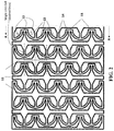
FIG. 2 is a top plan view of a portion of the expansion lattice of FIG. 1, taken from line A-A of FIG. 1.
FIG. 3A is an end view of the lattice of FIGS. 1-2.
FIG. 3B is an end view of an alternate embodiment of the invention, in which the longitudinal restricting beams are continuous and elliptical in shape.
FIG. 3C is an end view of another alternate embodiment of the invention, which is a composite of the embodiments of FIGS. 3A-3B.
FIG. 4 is a schematic stress-strain curve of an expansion lattice of the present invention.
FIG. 5 is a set of actual stress-strain curves of an expansion lattice of the present invention.
FIG. 6A is a photograph of the expansion lattice used to generate FIG. 4, taken at point A in FIG. 5.
FIG. 6B is a photograph of the expansion lattice used to generate FIG. 4, taken at point B in FIG. 5.
FIG. 6C is a photograph of the expansion lattice used to generate FIG. 4, taken at point C in FIG. 5.
FIG. 6D is a photograph of the expansion lattice used to generate FIG. 4, taken at point D in FIG. 5.
FIG. 7A is a schematic diagram of a clamping apparatus incorporating an expansion lattice of the invention, as well as a compression lattice, in a relaxed configuration.
FIG. 7B is a schematic diagram of the clamping apparatus of FIG. 7A, with the expansion lattice in an expanded configuration and the compression lattice in a compressed configuration.
FIG. 8 is a perspective view of a constant force compression lattice useful in carrying out the apparatus of FIGS. 7A-7B, with internal portions of the object omitted for clarity.
FIG. 9 is a first side view of the lattice of FIG. 8.
FIG. 10 is a second side view of the lattice of FIG. 8.
FIG. 11 is a top view of the lattice of FIG. 8.
DETAILED DESCRIPTION OF ILLUSTRATIVE EMBODIMENTS
The present invention is now described more fully hereinafter with reference to the accompanying drawings, in which embodiments of the invention are shown. This invention may, however, be embodied in many different forms and should not be construed as limited to the embodiments set forth herein; rather these embodiments are provided so that this disclosure will be thorough and complete and will fully convey the scope of the invention to those skilled in the art.
As used herein, the term “and/or” includes any and all possible combinations or one or more of the associated listed items, as well as the lack of combinations when interpreted in the alternative (“or”).
1. Methods of Making.
Objects or constructs as described herein can be produced by any suitable process, but are preferably produced by additive manufacturing, particularly by stereolithography, and most preferably by continuous liquid interface production (CLIP).
Techniques for additive manufacturing are known. Suitable techniques include bottom-up or top-down additive manufacturing, generally known as stereolithography. Such methods are known and described in, for example, U.S. Pat. No. 5,236,637 to Hull, U.S. Pat. Nos. 5,391,072 and 5,529,473 to Lawton, U.S. Pat. No. 7,438,846 to John, U.S. Pat. No. 7,892,474 to Shkolnik, U.S. Pat. No. 8,110,135 to El-Siblani, U.S. Patent Application Publication Nos. 2013/0292862 to Joyce, and US Patent Application Publication No. 2013/0295212 to Chen et al. The disclosures of these patents and applications are incorporated by reference herein in their entirety.
CLIP is known and described in, for example, U.S. Pat. Nos. 9,211,678; 9,205,601; and 9,216,546; and also in J. Tumbleston, D. Shirvanyants, N. Ermoshkin et al., Continuous liquid interface production of 3D Objects, Science 347, 1349-1352 (published online 16 Mar. 2015). See also R. Janusziewcz et al., Layerless fabrication with continuous liquid interface production, Proc. Natl. Acad. Sci. USA 113, 11703-11708 (Oct. 18, 2016). In some embodiments, CLIP employs features of a bottom-up three dimensional fabrication as described above, but the irradiating and/or said advancing steps are carried out while also concurrently maintaining a stable or persistent liquid interface between the growing object and the build surface or window, such as by: (i) continuously maintaining a dead zone of polymerizable liquid in contact with said build surface, and (ii) continuously maintaining a gradient of polymerization zone (such as an active surface) between the dead zone and the solid polymer and in contact with each thereof, the gradient of polymerization zone comprising the first component in partially cured form. In some embodiments of CLIP, the optically transparent member comprises a semipermeable member (e.g., a fluoropolymer), and the continuously maintaining a dead zone is carried out by feeding an inhibitor of polymerization through the optically transparent member, thereby creating a gradient of inhibitor in the dead zone and optionally in at least a portion of the gradient of polymerization zone. Other approaches for carrying out CLIP that can be used in the present invention and potentially obviate the need for a semipermeable “window” or window structure include utilizing a liquid interface comprising an immiscible liquid (see L. Robeson et al., WO 2015/164234, published Oct. 29, 2015), generating oxygen as an inhibitor by electrolysis (see I Craven et al., WO 2016/133759, published Aug. 25, 2016), and incorporating magnetically positionable particles to which the photoactivator is coupled into the polymerizable liquid (see J. Rolland, WO 2016/145182, published Sep. 15, 2016).
In one non-limiting embodiment, the object may be produced on a Carbon Inc., M1 additive manufacturing apparatus, available from Carbon, Inc., 1089 Mills Way, Redwood City, Calif. 94063 USA.
After the intermediate three-dimensional object is formed, it is optionally washed, optionally dried (e.g., air dried) and/or rinsed (in any sequence). It is then further cured, preferably by heating.
Heating may be active heating (e.g., in an oven, such as an electric, gas, solar oven or microwave oven, or combination thereof), or passive heating (e.g., at ambient temperature). Active heating will generally be more rapid than passive heating and in some embodiments is preferred, but passive heating—such as simply maintaining the intermediate at ambient temperature for a sufficient time to effect further cure—may in some embodiments also be employed.
2. Materials.
Any suitable material can be used as the polymerizable liquid or resin to carry out the present invention (including expansion lattices, compression lattices, and clamping apparatus comprising the two integrally formed with one another). Preferably, the material is one which produces an elastomeric product. In some embodiments, the objects are comprised of a polyurethane material (including polyurea materials). In some embodiments, the objects are produced from a dual cure stereolithography resin.
Dual cure stereolithography resins suitable for stereolithography techniques (particularly for CLIP) are described in J. Rolland et al., U.S. Pat. Nos. 9,453,142 and 9,598,606 (see also US Patent Application Pub. Nos. US 2016/0136889; 2016/0137838; and 2016/016077). These resins usually include a first polymerizable system typically polymerized by light (sometimes referred to as “Part A”) from which an intermediate object is produced, and also include at least a second polymerizable system (“Part B”) which is usually cured after the intermediate object is first formed, and which impart desirable structural and/or tensile properties to the final object.
In some embodiments, the polymerizable liquid is a Carbon, Inc. elastic polyurethane (EPU) resin such as EPU40, available from Carbon, Inc., 1089 Mills Way, Redwood City, Calif. 94063 USA.
3. Constant Force Expansion Lattice.
As noted above, and as shown in the non-limiting examples set forth in FIGS. 1-6 herein, a first aspect of the present invention is a constant force expansion construct, comprising a plurality of expandable layers, each expandable layer including: (a) a longitudinal restricting beam 11; and (b) a plurality of interconnected flexible biasing struts 12 connecting the longitudinal restricting beam of one expandable layer to another longitudinal restricting beam in a next adjacent expandable layer, the biasing struts being biased toward a compressed position and being movable between the compressed position and an expanded position in which a distance between successive longitudinal restricting beams is increased.
In some embodiments, each of the plurality of interconnected flexible biasing struts 12 comprises a curvilinear member 13 that is attached to the longitudinal restricting beam 11 by a lateral support member 14.
In some embodiments, the curvilinear member 13 of the flexible biasing struts 12 comprises a semi-circular shape in they compressed position with the lateral support extending from a midpoint of the semi-circular shape to the longitudinal restricting beam.
In some embodiments, the lateral support member comprises a substantially linear lateral support having a thickness that increases in a region adjacent the longitudinal restricting beam.
In some embodiments, the lateral support comprises (that is, may be referred to as) a first lateral support, and each of the plurality of interconnected flexible biasing struts comprises a second lateral support 15 extending from an endpoint of the semi-circular shape to the longitudinal restricting beam.
In some embodiments, the expandable layers each have a unit cell size of 10 or 20 microns (or less) up to 10 or 20 millimeters (or more).
In some embodiments, the plurality of expandable layers together have a height (Z dimension) of 10 or 20 unit cells (or less), up to 106 or 1012 unit cells (or more).
In some embodiments, the plurality of interconnected flexible biasing struts form an expandable region that has an expandable ratio (of pre-expanded distance to expanded distance) of at least 1:2 or 1:3, to 1:8 or 1:10, or more.
In some embodiments, the struts and beams are integrally formed with one another.
In some embodiments, the struts and beams are comprised of an elastomeric material.
In some embodiments, the struts and beams are comprised of polyurethane.
In some embodiments, the expandable layers are flat (as shown by the end beam 18 in FIG. 3A), curved (as shown by the end beam 18′ in FIG. 3B) or a combination thereof (such as shown by the end beam 18″ in FIG. 3C). Indeed, the expandable layers may be continuous or connected edge-to-edge to form a cylinder, as shown in FIG. 3B. An elliptical cylinder is indicated by FIG. 3B, but the cylindrical embodiments of the construct may have any suitable cross-sectional shape, such as round, hexagonal, rectangular, triangular, etc., including composites thereof (for example, as shown in FIG. 3C).
FIG. 4 shows a schematic example of a stress-strain curve of an expansion construct of the invention, with the region of relatively constant force indicated by the inflection zone. A slight inflection may occur during the pre-buckling phase, as indicated by the dashed line of otherwise overlapping curves, and some drift may occur during the inflection zone, while behavior still remains substantially non-Hookean until the later, linear elasticity, zone is reached. FIG. 5 shows stress strain curves for an actual lattice of the invention (see photographs in FIG. 6A-6D, corresponding to the configuration of the lattice at points A, B, C, and D in FIG. 5), indicating behavior substantially the same as shown in FIG. 4. The behavior of a “Hookean” spring is shown by the curve.
4. Clamping Apparatus Comprised of a Constant Force Expansion Lattice, and Optionally at Least One Compression Lattice.
As noted above and schematically illustrated in FIGS. 7A-7B, a further aspect of the invention is a clamping apparatus for engaging an object, comprising: (a) a pair of opposing members, each having an engagement surface; and (b) at least one, or at least a pair of, expansion constructs 10 as described above operatively connected to the opposing members, with the engagement surfaces facing one another.
In some embodiments, at least one of the opposing members comprises a Hookean or non-Hookean compression construct. In some more particularly embodiments, at least one, or both, of the compression constructs comprises a constant force compression construct.
In the embodiment of FIGS. 7A-7B, one of the opposing members is simply a flat, preferably rigid, member 22, while the other opposing member includes a compression lattice 20 connected to the expansion lattice 10 through an interconnecting member 21. A Transition member 23 is included on the compression lattice, with engagement surfaces 25, 26, facing each other. Thus a plurality of objects 30 of different sizes (represented by dashed lines) may be engaged, all across distance d, with substantially uniform force. While the compression lattice 20 (or other compression construct, such as an elastomeric foam) may be a conventional or “Hookean” compression material, in some embodiments (where particularly uniform clamping force may be desired, all with some cushioning effect, across a range of objects of different sizes), the compression material may itself be a constant force compression object, an example of which is discussed further below.
Note that while the engagement surfaces are shown flat in FIGS. 7A-7B, engagement surfaces of any suitable shape may be used, depending on the object to be clamped or engaged thereby. The object to be clamped may be an inanimate object or conventional “workpiece,” such as one to be repetitively engaged by a robotic device, or the object may be a limb, appendage, or body part of a human or animal subject. The clamping apparatus may itself be securely fastened to a work station or other relatively immobile object (e.g., directly, or via an intermediate adjustable component such as a robotic arm), or may be “free” and carry some other additional component to be temporarily clamped to the object (e.g., an electronic or electromechanical device, such as a transducer, detector, etc.)
While the apparatus may be made by any suitable technique, including as component parts assembled together, in some embodiments the entire clamping apparatus, including the expansion construct and the opposing members (optionally wherein at least one or both further comprise a compression construct) are all produced by the process of additive manufacturing, optionally but in some embodiments preferably simultaneously, from the same polymerizable resin, so that all components are integrally connected to one another. Components such as engagement surfaces, transition members, and interconnecting members may be of the same material and simply formed in a configuration, such as a lattice structure, that is substantially rigid as compared to the expansion lattice (and compression lattice is present), or the materials may be switched in the course of additive manufacture (as is known in the art).
5. Constant Force Compression Lattice.
As noted above, disclosed herein is a constant force compression construct. The construct includes (a) a plurality of compressible layers (e.g., compressible in an edge-wise direction), each compressible layer comprising a plurality of interconnected flexible struts configured as a regular hexagonal lattice of repeating unit cells, with the layers spaced apart from one another, and with the unit cells of each layer aligned with one another; and (b) a plurality of beams interconnecting each of the compressible layers with each respective adjacent compressible layer to form a three-dimensional lattice having an upper portion, a lower portion, and a compressible region therebetween, with the repeating unit cells contained in the compressible region. Optionally, but in some embodiments preferably, the construct further includes (c) a first force-dispersing segment (or “pad”) connected to the upper portion. Optionally, but in some embodiments preferably, the construct further includes (d) a second force-dispersing segment (or “pad’) connected to the lower portion. An example of one embodiment is shown in FIGS. 8-11.
In some embodiments of the foregoing, the compressible region (or “compressible lattice”) is anisotropically compressible in plane with the compressible layers and along the longest dimension of the hexagonal structures upon substantially constant (e.g., plus or minus five or ten percent) application of pressure (within the “plateau zone”, which does not including linear elasticity zones or densification zones typical in compressive stress-strain curves), and which compressible region rebounds to its prior pre-compressed dimension upon removal of the pressure (assuming not compressed to failure, in terminal regions of the densification zone).
In some embodiments, the compressible layers are flat (as shown in FIGS. 8-11), curved, or a combination thereof.
In some embodiments, the beams are parallel to one another (as shown in FIG. 8-11), radially arranged with respect to one another, or a combination thereof.
In some embodiments of the foregoing, the compressible region (or “compressible lattice”) has a compression ratio (of precompressed height to compressed height) of at least 2:1 or 3:1, to 8:1 or 10:1, or more.
In some embodiments of the foregoing, the compressible layers have a unit cell size of 10 or 20 microns (or less) up to 10 or 20 millimeters (or more). In some embodiments of the foregoing, the compressible layers have a height (that is, in the Z dimension) of 10 or 20 unit cells (or less), up to 106 or 1012 unit cells (or more).
In some embodiments, the struts and beams (and optionally, but preferably, the first and/or second force-dispersing elements) are integrally formed with one another.
In some embodiments, the struts and beams (and optionally, but preferably, the first and/or second force-dispersing elements) are comprised of an elastomeric material.
In some embodiments, the struts and beams (and optionally, but in some embodiments preferably, the first and/or second force-dispersing elements) are comprised of polyurethane.
The foregoing is illustrative of the present invention, and is not to be construed as limiting thereof. The invention is defined by the following claims, with equivalents of the claims to be included therein.

Claims (13)

We claim:
1. A constant force expansion construct, comprising a plurality of expandable layers, each expandable layer comprising:
(a) a longitudinal restricting beam; and
(b) a plurality of interconnected flexible biasing struts connecting the longitudinal restricting beam of one expandable layer to another longitudinal restricting beam in a next adjacent expandable layer, the biasing struts being biased toward a compressed position and being movable between the compressed position and an expanded position in which a distance between successive longitudinal restricting beams is increased.
2. The expansion construct of claim 1, wherein each of the plurality of interconnected flexible biasing struts comprises a curvilinear member that is attached to the longitudinal restricting beam by a lateral support member.
3. The expansion construct of claim 2, wherein the curvilinear member of the flexible biasing struts comprises a semi-circular shape in the compressed position with the lateral support extending from a midpoint of the semi-circular shape to the longitudinal restricting beam.
4. The expansion construct of claim 3, wherein the lateral support member comprises a substantially linear lateral support having a thickness that increases in a region adjacent the longitudinal restricting beam.
5. The expansion construct of claim 2, wherein the lateral support comprises a first lateral support, and each of the plurality of interconnected flexible biasing struts comprises a second lateral support extending from an endpoint of the semi-circular shape to the longitudinal restricting beam.
6. The apparatus of claim 1, wherein said expandable layers each have a unit cell size of 10 to 20 millimeters.
7. The apparatus of claim 1, wherein said plurality of expandable layers together have a height (Z dimension) of 10 unit cells (or less) to 1012 unit cells.
8. The expansion construct of claim 1, wherein the plurality of interconnected flexible biasing struts form an expandable region that has an expandable ratio (of pre-expanded distance to expanded distance) of at least 1:2 to 1:10.
9. The expansion construct of claim 1, wherein said struts and beams are integrally formed with one another.
10. The expansion construct of claim 1, wherein said struts and beams are comprised of an elastomeric material.
11. The expansion construct of claim 1, wherein said struts and beams are comprised of polyurethane.
12. The expansion construct of claim 1, wherein said expandable layers are flat, curved or a combination thereof, including cylindrical and composite constructs thereof.
13. The expansion construct of claim 1, wherein said construct is produced by the process of additive manufacturing.
US15/938,902 2017-05-31 2018-03-28 Constant force expansion lattice Active 2040-05-25 US11167395B2 (en)

Priority Applications (1)

Application Number Priority Date Filing Date Title
US15/938,902 US11167395B2 (en) 2017-05-31 2018-03-28 Constant force expansion lattice

Applications Claiming Priority (2)

Application Number Priority Date Filing Date Title
US201762512765P 2017-05-31 2017-05-31
US15/938,902 US11167395B2 (en) 2017-05-31 2018-03-28 Constant force expansion lattice

Publications (2)

Publication Number Publication Date
US20190039213A1 US20190039213A1 (en) 2019-02-07
US11167395B2 true US11167395B2 (en) 2021-11-09

Family

ID=65231949

Family Applications (1)

Application Number Title Priority Date Filing Date
US15/938,902 Active 2040-05-25 US11167395B2 (en) 2017-05-31 2018-03-28 Constant force expansion lattice

Country Status (1)

Country Link
US (1) US11167395B2 (en)

Cited By (2)

* Cited by examiner, † Cited by third party
Publication number Priority date Publication date Assignee Title
US11684104B2 (en) 2019-05-21 2023-06-27 Bauer Hockey Llc Helmets comprising additively-manufactured components
US11779821B2 (en) 2014-05-13 2023-10-10 Bauer Hockey Llc Sporting goods including microlattice structures

Families Citing this family (4)

* Cited by examiner, † Cited by third party
Publication number Priority date Publication date Assignee Title
US11426938B2 (en) 2018-02-21 2022-08-30 Carbon, Inc. Rapid wash system for additive manufacturing
US11230050B2 (en) 2018-02-27 2022-01-25 Carbon, Inc. Lattice base structures for additive manufacturing
US11541600B2 (en) 2018-03-20 2023-01-03 Carbon, Inc. Rapid wash carrier platform for additive manufacturing of dental models
US11565774B2 (en) 2018-10-03 2023-01-31 Adam Jon Noah Additive manufactured water resistant closed-cell lattice structure for marine hull cavities

Cited By (4)

* Cited by examiner, † Cited by third party
Publication number Priority date Publication date Assignee Title
US11779821B2 (en) 2014-05-13 2023-10-10 Bauer Hockey Llc Sporting goods including microlattice structures
US11794084B2 (en) 2014-05-13 2023-10-24 Bauer Hockey Llc Sporting goods including microlattice structures
US11844986B2 (en) 2014-05-13 2023-12-19 Bauer Hockey Llc Sporting goods including microlattice structures
US11684104B2 (en) 2019-05-21 2023-06-27 Bauer Hockey Llc Helmets comprising additively-manufactured components

Also Published As

Publication number Publication date
US20190039213A1 (en) 2019-02-07

Similar Documents

Publication Publication Date Title
US11167395B2 (en) Constant force expansion lattice
Jiang et al. Manufacturing, characteristics and applications of auxetic foams: A state-of-the-art review
Mir et al. Review of mechanics and applications of auxetic structures
Kolken et al. Auxetic mechanical metamaterials
Wang et al. Fabrication and mechanical properties of CFRP composite three-dimensional double-arrow-head auxetic structures
Virk et al. SILICOMB PEEK Kirigami cellular structures: mechanical response and energy dissipation through zero and negative stiffness
Prawoto Seeing auxetic materials from the mechanics point of view: a structural review on the negative Poisson’s ratio
George et al. Buckling and free vibration of nonuniformly heated functionally graded carbon nanotube reinforced polymer composite plate
Guo et al. Mechanical properties of 3D hybrid double arrow-head structure with tunable Poisson's ratio
Zhang et al. The negative Poisson's ratio in graphene-based carbon foams
Sahariah et al. A novel strategy to design lattice structures with zero Poisson’s ratio
Quadrini et al. Shape memory polymer composite unit with embedded heater
Zhang et al. Bending performance of 3D re-entrant and hexagonal metamaterials
Decroly et al. Optimization of phase-change material–elastomer composite and integration in kirigami-inspired voxel-based actuators
Joe et al. Jointless Bioinspired Soft Robotics by Harnessing Micro and Macroporosity
Akhmetshin et al. Analysis of stress and strain in the tetrachiral metamaterial with different kinds of unit cell connections
Gunel et al. Review on auxetic materials
Zanjani et al. Thermo-responsive and shape-morphing CF/GF composite skin: Full-field experimental measurement, theoretical prediction, and finite element analysis
Fu et al. Design and Mechanical Characterization of an S-Based TPMS Hollow Isotropic Cellular Structure.
Nash et al. Mechanical behavior of bio-inspired wavy adhesive bonding under shear
Darnal et al. An exploration of 3D printed freeform kerf structures
Zhang et al. A high load capacity and efficient-transporting inchworm-like crawling robot with bistable structure and pneumatic networks actuator
Shilko et al. Structural simulation of supercompressible materials
Khan et al. A Comparative Study of RTV-225 Silicone Elastomer and Natural Rubber Based Thermo-Elastomer for Soft Robotic Applications
Singh INVESTIGATION ON IMPACT STRENGTH OF ADDITIVE MANUFACTURED BIOMIMETIC STRUCTURE

Legal Events

Date Code Title Description
FEPP Fee payment procedure

Free format text: ENTITY STATUS SET TO UNDISCOUNTED (ORIGINAL EVENT CODE: BIG.); ENTITY STATUS OF PATENT OWNER: LARGE ENTITY

STPP Information on status: patent application and granting procedure in general

Free format text: DOCKETED NEW CASE - READY FOR EXAMINATION

STPP Information on status: patent application and granting procedure in general

Free format text: NON FINAL ACTION MAILED

STPP Information on status: patent application and granting procedure in general

Free format text: RESPONSE TO NON-FINAL OFFICE ACTION ENTERED AND FORWARDED TO EXAMINER

STPP Information on status: patent application and granting procedure in general

Free format text: NOTICE OF ALLOWANCE MAILED -- APPLICATION RECEIVED IN OFFICE OF PUBLICATIONS

STPP Information on status: patent application and granting procedure in general

Free format text: PUBLICATIONS -- ISSUE FEE PAYMENT VERIFIED

STCF Information on status: patent grant

Free format text: PATENTED CASE