US11166311B2 - Systems and methods utilizing channel spatial properties with CSMA - Google Patents
Systems and methods utilizing channel spatial properties with CSMA Download PDFInfo
- Publication number
- US11166311B2 US11166311B2 US15/910,798 US201815910798A US11166311B2 US 11166311 B2 US11166311 B2 US 11166311B2 US 201815910798 A US201815910798 A US 201815910798A US 11166311 B2 US11166311 B2 US 11166311B2
- Authority
- US
- United States
- Prior art keywords
- node
- wireless communication
- beamforming
- neighboring
- transmitter
- Prior art date
- Legal status (The legal status is an assumption and is not a legal conclusion. Google has not performed a legal analysis and makes no representation as to the accuracy of the status listed.)
- Active, expires
Links
Images


Classifications
-
- H—ELECTRICITY
- H04—ELECTRIC COMMUNICATION TECHNIQUE
- H04W—WIRELESS COMMUNICATION NETWORKS
- H04W74/00—Wireless channel access
- H04W74/08—Non-scheduled access, e.g. ALOHA
- H04W74/0808—Non-scheduled access, e.g. ALOHA using carrier sensing, e.g. carrier sense multiple access [CSMA]
- H04W74/0816—Non-scheduled access, e.g. ALOHA using carrier sensing, e.g. carrier sense multiple access [CSMA] with collision avoidance
-
- H—ELECTRICITY
- H04—ELECTRIC COMMUNICATION TECHNIQUE
- H04B—TRANSMISSION
- H04B17/00—Monitoring; Testing
- H04B17/30—Monitoring; Testing of propagation channels
- H04B17/309—Measuring or estimating channel quality parameters
- H04B17/318—Received signal strength
-
- H—ELECTRICITY
- H04—ELECTRIC COMMUNICATION TECHNIQUE
- H04W—WIRELESS COMMUNICATION NETWORKS
- H04W16/00—Network planning, e.g. coverage or traffic planning tools; Network deployment, e.g. resource partitioning or cells structures
- H04W16/14—Spectrum sharing arrangements between different networks
-
- H—ELECTRICITY
- H04—ELECTRIC COMMUNICATION TECHNIQUE
- H04W—WIRELESS COMMUNICATION NETWORKS
- H04W16/00—Network planning, e.g. coverage or traffic planning tools; Network deployment, e.g. resource partitioning or cells structures
- H04W16/24—Cell structures
- H04W16/28—Cell structures using beam steering
-
- H—ELECTRICITY
- H04—ELECTRIC COMMUNICATION TECHNIQUE
- H04W—WIRELESS COMMUNICATION NETWORKS
- H04W72/00—Local resource management
- H04W72/04—Wireless resource allocation
- H04W72/044—Wireless resource allocation based on the type of the allocated resource
- H04W72/046—Wireless resource allocation based on the type of the allocated resource the resource being in the space domain, e.g. beams
-
- H—ELECTRICITY
- H04—ELECTRIC COMMUNICATION TECHNIQUE
- H04W—WIRELESS COMMUNICATION NETWORKS
- H04W84/00—Network topologies
- H04W84/02—Hierarchically pre-organised networks, e.g. paging networks, cellular networks, WLAN [Wireless Local Area Network] or WLL [Wireless Local Loop]
- H04W84/10—Small scale networks; Flat hierarchical networks
- H04W84/12—WLAN [Wireless Local Area Networks]
-
- Y—GENERAL TAGGING OF NEW TECHNOLOGICAL DEVELOPMENTS; GENERAL TAGGING OF CROSS-SECTIONAL TECHNOLOGIES SPANNING OVER SEVERAL SECTIONS OF THE IPC; TECHNICAL SUBJECTS COVERED BY FORMER USPC CROSS-REFERENCE ART COLLECTIONS [XRACs] AND DIGESTS
- Y02—TECHNOLOGIES OR APPLICATIONS FOR MITIGATION OR ADAPTATION AGAINST CLIMATE CHANGE
- Y02D—CLIMATE CHANGE MITIGATION TECHNOLOGIES IN INFORMATION AND COMMUNICATION TECHNOLOGIES [ICT], I.E. INFORMATION AND COMMUNICATION TECHNOLOGIES AIMING AT THE REDUCTION OF THEIR OWN ENERGY USE
- Y02D30/00—Reducing energy consumption in communication networks
- Y02D30/70—Reducing energy consumption in communication networks in wireless communication networks
Definitions
- the field of the disclosure relates generally to wireless communication networks, and more particularly, to wireless communication networks utilizing carrier sense multiple access (CSMA).
- CSMA carrier sense multiple access
- CSMA with collision avoidance is a network multiple access method, sometimes referred to as “listen-before-talk” (LBT), in which nodes utilize carrier sensing, but attempt to avoid collisions by transmitting only when the channel is sensed to be idle (i.e., not being used).
- LBT listen-before-talk
- the CSMA/CA protocol typically operates in the data link layer of the telecommunication model of the network.
- Conventional Wi-Fi, Long Term Evolution (LTE) Licensed Assisted Access (LAA), and MulteFire technologies have recently adopted the CSMA/CA scheme as a mechanism for medium access control (MAC).
- a transmitter/transceiver of a node defers its transmission (when another node is detected) and applies an additional back off time before starting its own transmission. During this back off time, the node monitors the channel and performs clear channel assessment (CCA). If the channel is not busy at the end of this period, the transmitter/transceiver initiates transmission. The transmitting node then monitors the environment using uniform a beam-pattern, listening for transmissions from all directions.
- CCA clear channel assessment
- FIG. 1 is a schematic illustration of a conventional wireless transmission system 100 employing CSMA/CA for a uniform beam pattern 102 radiating from a central transmitter 104 .
- System 100 implements a CSMA/CA protocol in a Wi-Fi/LTE LAA environment.
- Central transmitter 104 is, for example, a transmitting access point (AP).
- System 100 includes an intended mobile user 106 , which wirelessly receives signals from central transmitter 104 over a communication link 108 under consideration.
- System 100 further includes a plurality of neighboring APs 110 and a plurality of neighboring mobile users 112 , respectively communicating over neighboring links 114 .
- the respective APs and mobile users are illustrated as having multiple antennas.
- a given AP will typically have more antennas and more signal processing capability than a typical mobile user.
- Operation of neighboring APs 110 and neighboring mobile users 112 generates interferences 116 to and from central transmitter 104 . Because beam pattern 102 is uniform in all directions from central transmitter 104 , central transmitter backs off equally in the respective focus direction of each interference 116 , when detected, and therefore represents an inefficient application of transmission resources.
- a wireless communication node includes a transmitting portion configured to transmit over a wireless communication channel a plurality of data packets to a first neighboring node, a receiving portion configured to detect the first neighboring node, and a processor configured to calculate a beamforming vector for the first neighboring node and direct the transmitting portion to transmit the plurality of data packets to the first neighboring node with beamforming based on the calculated beamforming vector.
- a method for transmitting over a wireless communication channel is provided.
- the method is implemented by a first node employing a carrier sense multiple access (CSMA) protocol.
- the method includes steps of detecting channel state information of a second node within a transmission vicinity of the first node, calculating a beamforming vector to transmit data from the first node to the second node, performing clear channel assessment on the wireless communication channel using the calculated beamforming vector, measuring an average received power of the wireless communication channel based on the clear channel assessment, determining that the measured average received power of the wireless communication channel is less than a predetermined energy detection threshold, and initiating, by the first node, a data transmission with beamforming over the wireless communication channel.
- CSMA carrier sense multiple access
- FIG. 1 is a schematic illustration of a conventional wireless transmission system employing CSMA/CA for a uniform beam pattern.
- FIG. 2 is a schematic illustration of a wireless transmission system employing CSMA/CA using a beamforming pattern, according to an embodiment.
- FIG. 3 is a flow chart diagram of an exemplary transmission process for the system depicted in FIG. 2 .
- FIG. 4 is a sequence diagram for an exemplary coexistence process which may be implemented for a non-beamforming transmission, according to an embodiment.
- FIG. 5 is a sequence diagram for an exemplary coexistence process which may be implemented for a beamforming transmission, according to an embodiment.
- Approximating language may be applied to modify any quantitative representation that could permissibly vary without resulting in a change in the basic function to which it is related. Accordingly, a value modified by a term or terms, such as “about,” “approximately,” and “substantially,” are not to be limited to the precise value specified. In at least some instances, the approximating language may correspond to the precision of an instrument for measuring the value.
- range limitations may be combined and/or interchanged; such ranges are identified and include all the sub-ranges contained therein unless context or language indicates otherwise.
- “User equipment” includes an electronic device or system utilizing a technology protocol such as LTE
- “Wi-Fi device” includes an electronic device or node, such as an AP, station, or STA, that is capable of utilizing an existing 802.11 protocol.
- “Mobile user” may include a user equipment and/or a Wi-Fi device, and may further include, without limitation, one or more of a laptop, a personal computer (PC), a personal digital assistant (PDA), a Wi-Fi phone, a smartphone, and a cellular telephone.
- the respective nodes and user devices may include a transceiver or transmitter and receiver combination, and/or an 802.11-conforming MAC layer and physical (PHY) layer interface to a wireless medium.
- the following description features systems and methods for incorporating the spatial properties of a channel transmission in a CSMA scheme, which may include a CSMA/CA access system.
- the present embodiments relate to operation and management of a transmitter or transceiver using the spatial properties of the transmission channel, and methods for efficient coexistence of neighboring nodes utilizing CSMA/CA.
- a CSMA strategy is implemented for a transmitting node employing beamforming to focus the node's transmission energy in a spatial direction of interest to reduce the interference from and to other nodes.
- RTS, CTS, and ACK frame transmissions may be transmitted according to conventional techniques, without beamforming, to allow continued measurement of potential interferers.
- spatial diversity of the channel is utilized to enable increased communication in dense deployments of nodes.
- Beamforming is a multiple antenna transmission technique that focuses radiated energy in the direction(s) of interest to provide additional gains at the receiver.
- the systems and methods herein advantageously employ beamforming to focus the signal of the transmitter in limited directions, that is, more in some directions than others. The signal therefore will not cause uniform interference to other nodes in all directions. Hence, because it is inefficient for the transmitter to back off signals in all directions at the same energy detection level, the transmitter of the present embodiments backs off only in directions overlapping with its beamformed transmission.
- the present embodiments achieve beamforming transmission primarily in two different ways: (1) based on the channel measurement of the reverse link and making use of channel reciprocity (applicable, for example, with time division duplex (TDD)); or (2) based on the channel measurement and feedback from the receiver.
- TDD time division duplex
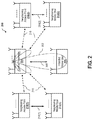
- the radiated energy is focused along main reflected paths, toward an intended node, thereby reducing interference to other users/nodes, as shown in FIG. 2 , below.
- FIG. 2 is a schematic illustration of a wireless transmission system 200 employing CSMA/CA, and using a beamforming pattern 202 transmitting from a central transmitter 204 .
- System 200 is architecturally similar to system 100 , FIG. 1 , and also implements a CSMA/CA protocol in a Wi-Fi/LTE LAA environment, but implements beamforming instead of a uniform beam pattern.
- central transmitter 204 is a transmitting access point (AP).
- System 200 includes an intended mobile user 206 , which wirelessly receives signals from central transmitter 204 over a communication link 208 under consideration.
- System 200 further includes a plurality of neighboring APs 210 and a plurality of neighboring mobile users 212 , respectively communicating over neighboring links 214 .
- the respective APs and mobile users have multiple antennas, but may have more or fewer, and a particular AP may have more antennas and signal processing capability than a particular mobile user.
- the transmitted energy of central transmitter 204 is directed toward intended mobile user 206 , and would only back off when experiencing interference in the direction of beamforming pattern 202 , or significant overlap of energy in portions thereof. Energy and power of central transmitter 204 may therefore be more efficiently managed and distributed according to the actual energy radiated a given direction.
- central transmitter 204 acquires channel vector information of intended mobile user 206 , and then performs CCA using the channel vector instead of the uniform channel sensing employed in system 100 .
- CCA using the channel vector thus provides more accurate information regarding the interference that will actually be caused by central transmitter 204 along the channel vector.
- the effect of interference 216 greatly varies but according to the energy level actually radiated in the direction of the respective portions of beamforming pattern 202 .
- interferences 216 ( 1 ) and 216 ( 4 ) are almost nonexistent, while the effect of interferences 216 ( 2 ) and 216 ( 3 ) is relatively minimal, since interferences 216 ( 2 ) and 216 ( 3 ) each only overlap relatively minor portions of beamforming pattern 202 .
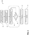
- FIG. 3 is a flow chart diagram of an exemplary transmission process 300 for system 200 , FIG. 2 .
- process 300 may be implemented by the MAC layer or PHY layer (not shown in this example) of central transmitter 206 in system 200 , or a processor thereof.
- process 300 begins at step 302 , in which the reverse link channel is measured.
- the reverse link channel is measured with sounding.
- the reverse link channel is measured from the preamble.
- step 304 the beamforming vector w u is calculated to transmit data to a user u (i.e., intended mobile user 206 , FIG. 2 .
- step 306 as an improvement over conventional beamforming techniques, process 300 performs CCA using the beamforming vector w u , and the received power therefrom, P CCA , is then represented by
- Step 308 is a decision step. In step 308 , process 300 determines if the received power PCCA is less than an energy detection threshold (ED threshold ). If P CCA ⁇ ED threshold , then process 300 proceeds to step 310 . If P CCA ⁇ ED threshold , then process 300 engages a back off scheme and returns to step 306 .
- ED threshold an energy detection threshold
- process 300 transmits a short message, or an RTS/CTS exchange in the conventional manner, without having to use the beamforming vector w u .
- process 300 initiates transmission (i.e., by central transmitter 204 , FIG. 2 ) if a CTS or an ACK is received at the receiver or receiving portion (not separately shown) of central transmitter 204 .
- a transmitting node e.g., central transmitter 204 , FIG. 2
- a transmitting node may be further configured to transmit RTS, CTS, and ACK/NACK frames, messages, or transmissions to neighboring nodes apart from the beamforming to mitigate this potential problem.
- FIG. 4 is a sequence diagram for an exemplary coexistence process 400 which may be implemented for a non-beamforming transmission.
- process 400 illustrates steps relating to a non-beamforming transmission from a transmitting node 402 to a receiving node 404 in the vicinity of an interferer candidate node 406 . That is, transmitting node 402 is configured to implement beamforming, but interferer candidate node 406 does not implement beamforming.
- process 400 may execute the following steps, which are not necessarily required to be in the order listed, except where so clearly designated as being dependent on a prior step.
- process 400 includes a first transmission subprocess 408 and a second transmission subprocess 410 .
- First transmission subprocess 408 occurs without beamforming, and second transmission subprocess 410 utilizes beamforming in the transmission.
- Process 400 begins with first subprocess 408 , and step S 412 .
- transmitting node 402 transmits RTS data (an “RTS”) to receiving node 404 .
- receiving node 404 transmits responsive CTS data (a “CTS”) to transmitting node 402 .
- CTS responsive CTS data
- the CTS is also received by interferer candidate node 406 .
- interferer candidate node 406 upon detection of the CTS (i.e., from step S 414 (B)) CCA may be performed, and interferer candidate node 406 may be configured to, in step S 416 , defer its transmission due to detection of the CTS.
- first transmission subprocess 408 i.e., data packets or ACK packets
- the preamble of the respective packet is transmitted without beamforming to allow other nodes to detect the ongoing transmission.
- the RTS/CTS messages are also transmitted without beamforming.
- Second transmission subprocess 410 begins at step S 418 , where transmitting node 402 calculates the beamforming vector. Second transmission subprocess 410 then proceeds to step S 420 , where transmitting node 402 transmits one or more data transmissions with beamforming to receiving node 404 . Upon receipt of the data transmission(s) with beamforming, in step S 422 , receiving node 404 transmits an ACK to transmitting node 402 .
- an innovative CSMA strategy is provided for a transmitting node to employ beamforming to focus its energy toward a spatial direction of interest, thereby reducing interference to other neighboring nodes in the vicinity. Because other neighboring nodes may still transmit energy in all directions (e.g., where the neighboring nodes employ a uniform beam pattern), and intended receiver may still experience interference, and not hear the transmitted signal.
- the advantageous process described with respect to FIG. 4 significantly mitigates this potential problem.
- transmitting nodes that intend to begin transmission with beamforming will advantageously first exchange small data packets and/or ACK packets, or RTS/CTS messages, without beamforming to announce the impending transmission. This exchange of small amounts of data will require some additional energy from the transmitting node, but this additional transmission energy is significantly less than the amount of transmission energy saved through the efficient use of beamforming described herein.
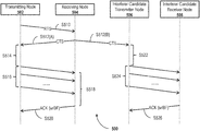
- FIG. 5 is a sequence diagram for an exemplary coexistence process 500 which may be implemented for a beamforming transmission.
- process 500 illustrates steps relating to a beamforming transmission from a transmitting node 502 to a receiving node 504 in the vicinity of an interferer candidate transmitter node 506 and an interferer candidate receiver node 508 that also employ beamforming.
- process 500 may execute the following steps, which are not necessarily required to be in the order listed, except where so clearly designated as being dependent on a prior step.
- Process 500 begins at step S 510 .
- transmitting node 502 transmits an RTS to receiving node 504 .
- receiving node 504 transmits a responsive CTS to transmitting node 502 .
- transmitting node 502 Upon detection of the CTS by transmitting node 502 (i.e., from step S 512 (A)), transmitting node 502 performs transmission processing similar to second transmission subprocess 410 , FIG. 4 . That is, in step S 514 , transmitting node 502 calculates the beamforming vector, and in step S 516 , transmitting node 502 transmits one or more data transmissions with beamforming to receiving node 504 .
- Process 500 then differs from second transmission subprocess 410 , in that upon receipt of the data transmission(s) with beamforming, in step S 518 , receiving node 504 is configured to calculate the beamforming vector from the received data transmission(s). In step S 520 , receiving node 504 then transmits an ACK transmission with beamforming to transmitting node 502 .
- This ACK transmission is thus different from that described above with respect to process 400 (i.e., step S 422 ), in that the ACK of process 400 is not transmitted with beamforming (or the beamforming is optional).
- interferer candidate transmitter node 506 upon detection of the CTS (i.e., from step S 512 (B)), performs CCA with a beamforming vector targeting interferer candidate receiver node 508 .
- interferer candidate transmitter node 506 transmits one or more data transmissions with beamforming to interferer candidate receiver node 508 .
- interferer candidate receiver node 508 transmits an ACK transmission with beamforming to interferer candidate transmitter node 506 .
- preambles may be transmitted without beamforming to allow other nodes to detect the ongoing transmission.
- the RTS/CTS messages may also be transmitted without beamforming.
- CSMA strategies are provided for a transmitting node to employ beamforming to significantly reduce transmit power in unneeded directions, whether in the vicinity of a neighboring node utilizing beamforming, or a node that does not utilized beamforming.
- particular portions thereof may be implemented alone or in combination with one or more of the other respective portions.
- the steps of the several processes may be implemented simultaneously, or in succession, except where a particular order is expressly stated.
- a transmitter/transceiver or node utilizing beamforming is configured to a particular channel of the wireless spectrum, and may adapt its protocol in order to maintain efficiency through utilization of the spatial properties of the channel.
- the novel systems and methods described above realize significant advantages over conventional systems that implement CSMA or utilize beamforming.
- the present embodiments implement innovative techniques to more efficiently utilize transmitter power according to the spatial properties of the channel, and according to the spatial beam pattern of neighboring or interfering nodes, when encountered.
- Algorithms to implement any or all the above described processes or techniques may be implemented within an application processor, a MAC co-processor, or the UMAC/LMAC layers of supporting architecture of a station and/or an AP, for the respective processor of a node transmitter, receiver, or transceiver.
- Some embodiments involve the use of one or more electronic or computing devices.
- Such devices typically include a processor or controller, such as a general purpose central processing unit (CPU), a graphics processing unit (GPU), a microcontroller, a reduced instruction set computer (RISC) processor, an application specific integrated circuit (ASIC), a programmable logic circuit (PLC), a field programmable gate array (FPGA), a digital signal processing (DSP) device, and/or any other circuit or processor capable of executing the functions described herein.
- the processes described herein may be encoded as executable instructions embodied in a computer readable medium, including, without limitation, a storage device and/or a memory device. Such instructions, when executed by a processor, cause the processor to perform at least a portion of the methods described herein.
- the above examples are exemplary only, and thus are not intended to limit in any way the definition and/or meaning of the term “processor.”
Landscapes
- Engineering & Computer Science (AREA)
- Computer Networks & Wireless Communication (AREA)
- Signal Processing (AREA)
- Quality & Reliability (AREA)
- Physics & Mathematics (AREA)
- Electromagnetism (AREA)
- Mobile Radio Communication Systems (AREA)
Abstract
Description
Step 308 is a decision step. In
Claims (17)
Priority Applications (3)
| Application Number | Priority Date | Filing Date | Title |
|---|---|---|---|
| US15/910,798 US11166311B2 (en) | 2017-03-02 | 2018-03-02 | Systems and methods utilizing channel spatial properties with CSMA |
| US15/950,815 US10757735B2 (en) | 2017-03-02 | 2018-04-11 | Systems and methods for Wi-Fi latency reduction in DOCSIS backhaul |
| US17/001,583 US11419149B2 (en) | 2017-03-02 | 2020-08-24 | Systems and methods for latency reduction in backhaul |
Applications Claiming Priority (2)
| Application Number | Priority Date | Filing Date | Title |
|---|---|---|---|
| US201762466098P | 2017-03-02 | 2017-03-02 | |
| US15/910,798 US11166311B2 (en) | 2017-03-02 | 2018-03-02 | Systems and methods utilizing channel spatial properties with CSMA |
Related Child Applications (1)
| Application Number | Title | Priority Date | Filing Date |
|---|---|---|---|
| US15/950,815 Continuation-In-Part US10757735B2 (en) | 2017-03-02 | 2018-04-11 | Systems and methods for Wi-Fi latency reduction in DOCSIS backhaul |
Publications (2)
| Publication Number | Publication Date |
|---|---|
| US20180255582A1 US20180255582A1 (en) | 2018-09-06 |
| US11166311B2 true US11166311B2 (en) | 2021-11-02 |
Family
ID=63355510
Family Applications (1)
| Application Number | Title | Priority Date | Filing Date |
|---|---|---|---|
| US15/910,798 Active 2038-06-13 US11166311B2 (en) | 2017-03-02 | 2018-03-02 | Systems and methods utilizing channel spatial properties with CSMA |
Country Status (1)
| Country | Link |
|---|---|
| US (1) | US11166311B2 (en) |
Families Citing this family (2)
| Publication number | Priority date | Publication date | Assignee | Title |
|---|---|---|---|---|
| US11277865B2 (en) | 2017-05-30 | 2022-03-15 | Huawei Technologies Co., Ltd. | Methods and system for LBT threshold setting for directional reception and transmission |
| US12615523B2 (en) * | 2023-04-27 | 2026-04-28 | Hewlett Packard Enterprise Development Lp | AP live upgrading mechanism in WiFi-7 |
Citations (10)
| Publication number | Priority date | Publication date | Assignee | Title |
|---|---|---|---|---|
| US20070298742A1 (en) * | 2006-06-27 | 2007-12-27 | Qualcomm Incorporated | Method and system for providing beamforming feedback in wireless communication systems |
| US20140362840A1 (en) * | 2013-06-07 | 2014-12-11 | Broadcom Corporation | Inter-AP coordination and synchronization within wireless communications |
| US20150103707A1 (en) * | 2013-10-10 | 2015-04-16 | At&T Intellectual Property I. L.P. | Method and apparatus for reducing energy consumption of radio communications in a wireless sensor network |
| US20150281993A1 (en) * | 2014-03-28 | 2015-10-01 | Magnolia Broadband Inc. | System and method for backhaul based sounding feedback |
| US20160105227A1 (en) * | 2013-07-23 | 2016-04-14 | Huawei Technologies Co., Ltd. | Data Transmission Method and Apparatus |
| US20170325222A1 (en) * | 2016-05-04 | 2017-11-09 | Laurent Cariou | Spatial reuse training for channel access schemes |
| US20180176921A1 (en) * | 2016-12-20 | 2018-06-21 | Intel IP Corporation | Report for inter-bss interference avoidance |
| US20180242364A1 (en) * | 2015-08-21 | 2018-08-23 | Lg Electronics Inc. | Method for channel access in wireless communication system and apparatus for performing same |
| US20180242176A1 (en) * | 2015-03-05 | 2018-08-23 | Zte Corporation | Channel Detection Method and Apparatus |
| US20180270038A1 (en) * | 2015-01-09 | 2018-09-20 | Interdigital Patent Holdings, Inc. | Bss-color enhanced transmission in wlans (bss-cet) |
-
2018
- 2018-03-02 US US15/910,798 patent/US11166311B2/en active Active
Patent Citations (10)
| Publication number | Priority date | Publication date | Assignee | Title |
|---|---|---|---|---|
| US20070298742A1 (en) * | 2006-06-27 | 2007-12-27 | Qualcomm Incorporated | Method and system for providing beamforming feedback in wireless communication systems |
| US20140362840A1 (en) * | 2013-06-07 | 2014-12-11 | Broadcom Corporation | Inter-AP coordination and synchronization within wireless communications |
| US20160105227A1 (en) * | 2013-07-23 | 2016-04-14 | Huawei Technologies Co., Ltd. | Data Transmission Method and Apparatus |
| US20150103707A1 (en) * | 2013-10-10 | 2015-04-16 | At&T Intellectual Property I. L.P. | Method and apparatus for reducing energy consumption of radio communications in a wireless sensor network |
| US20150281993A1 (en) * | 2014-03-28 | 2015-10-01 | Magnolia Broadband Inc. | System and method for backhaul based sounding feedback |
| US20180270038A1 (en) * | 2015-01-09 | 2018-09-20 | Interdigital Patent Holdings, Inc. | Bss-color enhanced transmission in wlans (bss-cet) |
| US20180242176A1 (en) * | 2015-03-05 | 2018-08-23 | Zte Corporation | Channel Detection Method and Apparatus |
| US20180242364A1 (en) * | 2015-08-21 | 2018-08-23 | Lg Electronics Inc. | Method for channel access in wireless communication system and apparatus for performing same |
| US20170325222A1 (en) * | 2016-05-04 | 2017-11-09 | Laurent Cariou | Spatial reuse training for channel access schemes |
| US20180176921A1 (en) * | 2016-12-20 | 2018-06-21 | Intel IP Corporation | Report for inter-bss interference avoidance |
Also Published As
| Publication number | Publication date |
|---|---|
| US20180255582A1 (en) | 2018-09-06 |
Similar Documents
| Publication | Publication Date | Title |
|---|---|---|
| EP4099588B1 (en) | Method and system for detecting idle channel in wireless communication system | |
| US11419149B2 (en) | Systems and methods for latency reduction in backhaul | |
| US20170180103A1 (en) | Radio configuration optimization for full-duplex communications | |
| US9420597B2 (en) | Scheduling method and apparatus for use in D2D communication system | |
| KR20160048110A (en) | Adaptive rts/cts in high-efficiency wireless communications | |
| US10819159B2 (en) | Methods of wireless power transfer by energy signal transfer apparatus operating in the same frequency band as wireless local area network in wireless power transfer energy harvesting system and energy signal transfer apparatuses for performing the same | |
| US10660132B2 (en) | Systems and methods for signal detection using PHY layer processing | |
| US20170150492A1 (en) | Wireless communication system, access point, and wireless device | |
| EP3182784B1 (en) | Method and apparatus for adjusting clear channel assessment (cca) threshold | |
| US10033496B2 (en) | Methods used in serving radio node and control node, and associated devices | |
| EP3235315B1 (en) | Methods used in network node, and receiving and transmitting nodes of link, and associated devices | |
| US10499251B2 (en) | Methods used in control nodes, and associated control nodes | |
| CN110226357B (en) | Method for channel access and related network node | |
| US9137673B2 (en) | Interference control system for simultaneously supporting low power communication and high spectral efficient communication | |
| JP5725552B2 (en) | Wireless communication apparatus, communication system, communication processing method, and program | |
| US11166311B2 (en) | Systems and methods utilizing channel spatial properties with CSMA | |
| US11039472B2 (en) | MAC protocol for directive transmissions | |
| US20080170558A1 (en) | Techniques for transmission protection for wireless networks | |
| Moon et al. | A cooperative CDMA-based multi-channel MAC protocol for mobile ad hoc networks | |
| EP3586534A1 (en) | Reconfiguration of listen-after-talk procedure | |
| KR20160106964A (en) | Communication control method in wireless communication system | |
| Nadeem | How Conservative IEEE 802.11 DCF is when using Directional Antenna? |
Legal Events
| Date | Code | Title | Description |
|---|---|---|---|
| FEPP | Fee payment procedure |
Free format text: ENTITY STATUS SET TO UNDISCOUNTED (ORIGINAL EVENT CODE: BIG.); ENTITY STATUS OF PATENT OWNER: SMALL ENTITY |
|
| AS | Assignment |
Owner name: CABLE TELEVISION LABORATORIES, INC, COLORADO Free format text: ASSIGNMENT OF ASSIGNORS INTEREST;ASSIGNOR:KECICIOGLU, BALKAN;REEL/FRAME:045203/0984 Effective date: 20180308 |
|
| FEPP | Fee payment procedure |
Free format text: ENTITY STATUS SET TO SMALL (ORIGINAL EVENT CODE: SMAL); ENTITY STATUS OF PATENT OWNER: SMALL ENTITY |
|
| STPP | Information on status: patent application and granting procedure in general |
Free format text: PRE-INTERVIEW COMMUNICATION MAILED |
|
| STPP | Information on status: patent application and granting procedure in general |
Free format text: RESPONSE TO NON-FINAL OFFICE ACTION ENTERED AND FORWARDED TO EXAMINER |
|
| STPP | Information on status: patent application and granting procedure in general |
Free format text: NON FINAL ACTION MAILED |
|
| STPP | Information on status: patent application and granting procedure in general |
Free format text: RESPONSE TO NON-FINAL OFFICE ACTION ENTERED AND FORWARDED TO EXAMINER |
|
| STPP | Information on status: patent application and granting procedure in general |
Free format text: FINAL REJECTION MAILED |
|
| STPP | Information on status: patent application and granting procedure in general |
Free format text: RESPONSE AFTER FINAL ACTION FORWARDED TO EXAMINER |
|
| STPP | Information on status: patent application and granting procedure in general |
Free format text: RESPONSE TO NON-FINAL OFFICE ACTION ENTERED AND FORWARDED TO EXAMINER |
|
| STPP | Information on status: patent application and granting procedure in general |
Free format text: NOTICE OF ALLOWANCE MAILED -- APPLICATION RECEIVED IN OFFICE OF PUBLICATIONS |
|
| STPP | Information on status: patent application and granting procedure in general |
Free format text: PUBLICATIONS -- ISSUE FEE PAYMENT VERIFIED |
|
| STCF | Information on status: patent grant |
Free format text: PATENTED CASE |
|
| FEPP | Fee payment procedure |
Free format text: ENTITY STATUS SET TO UNDISCOUNTED (ORIGINAL EVENT CODE: BIG.); ENTITY STATUS OF PATENT OWNER: LARGE ENTITY |
|
| MAFP | Maintenance fee payment |
Free format text: PAYMENT OF MAINTENANCE FEE, 4TH YEAR, LARGE ENTITY (ORIGINAL EVENT CODE: M1551); ENTITY STATUS OF PATENT OWNER: LARGE ENTITY Year of fee payment: 4 |