US11150693B2 - Adaptable radio frequency systems and methods - Google Patents
Adaptable radio frequency systems and methods Download PDFInfo
- Publication number
- US11150693B2 US11150693B2 US14/641,135 US201514641135A US11150693B2 US 11150693 B2 US11150693 B2 US 11150693B2 US 201514641135 A US201514641135 A US 201514641135A US 11150693 B2 US11150693 B2 US 11150693B2
- Authority
- US
- United States
- Prior art keywords
- electronic device
- radio frequency
- housing
- settings
- frequency system
- Prior art date
- Legal status (The legal status is an assumption and is not a legal conclusion. Google has not performed a legal analysis and makes no representation as to the accuracy of the status listed.)
- Active, expires
Links
Images


Classifications
-
- G—PHYSICS
- G06—COMPUTING OR CALCULATING; COUNTING
- G06F—ELECTRIC DIGITAL DATA PROCESSING
- G06F1/00—Details not covered by groups G06F3/00 - G06F13/00 and G06F21/00
- G06F1/16—Constructional details or arrangements
- G06F1/1613—Constructional details or arrangements for portable computers
- G06F1/163—Wearable computers, e.g. on a belt
-
- G—PHYSICS
- G06—COMPUTING OR CALCULATING; COUNTING
- G06F—ELECTRIC DIGITAL DATA PROCESSING
- G06F1/00—Details not covered by groups G06F3/00 - G06F13/00 and G06F21/00
- G06F1/16—Constructional details or arrangements
- G06F1/1613—Constructional details or arrangements for portable computers
- G06F1/1633—Constructional details or arrangements of portable computers not specific to the type of enclosures covered by groups G06F1/1615 - G06F1/1626
- G06F1/1684—Constructional details or arrangements related to integrated I/O peripherals not covered by groups G06F1/1635 - G06F1/1675
- G06F1/1698—Constructional details or arrangements related to integrated I/O peripherals not covered by groups G06F1/1635 - G06F1/1675 the I/O peripheral being a sending/receiving arrangement to establish a cordless communication link, e.g. radio or infrared link, integrated cellular phone
-
- G—PHYSICS
- G06—COMPUTING OR CALCULATING; COUNTING
- G06F—ELECTRIC DIGITAL DATA PROCESSING
- G06F1/00—Details not covered by groups G06F3/00 - G06F13/00 and G06F21/00
- G06F1/16—Constructional details or arrangements
- G06F1/1613—Constructional details or arrangements for portable computers
- G06F1/1633—Constructional details or arrangements of portable computers not specific to the type of enclosures covered by groups G06F1/1615 - G06F1/1626
- G06F1/1656—Details related to functional adaptations of the enclosure, e.g. to provide protection against EMI, shock, water, or to host detachable peripherals like a mouse or removable expansions units like PCMCIA cards, or to provide access to internal components for maintenance or to removable storage supports like CDs or DVDs, or to mechanically mount accessories
Definitions
- the present disclosure relates generally to radio frequency systems and, more particularly, to adaptation of radio frequency system configuration settings based upon electronic device housing and/or accessories.
- the radio frequency system may include a transceiver that receives a digital representation of data as a digital electrical signal and generates an analog representation of the data as an analog electrical signal.
- a power amplifier may then amplify the analog electrical signal to a desired output power for wireless transmittance via an antenna at a desired radio frequency, such as an assigned resource block or channel.
- a “channel” is intended to describe a range of frequencies and a “resource block” is intended to describe a range of frequencies within the channel.
- Electronic devices are becoming increasingly customizable. For example, these electronic devices may utilize any number of customizable housings and/or accessories that may have an impact on the electronic devices' radio frequency performance.
- an electronic device such as a smart watch or tablet computer may include a customizable housing material, such as: gold, stainless steel, aluminum, ceramic, and/or plastic.
- these electronic devices may be coupled to accessories that may impact radio frequency transmission and/or reception.
- a watch may include interchangeable band that have varying characteristics, such as varied densities (e.g., mesh bands vs. link bands), shapes (e.g., slim vs. thick bands), materials (e.g., leather, rubber, and/or metal), etc.
- a tablet computer may work with a cover, case, and/or other accessories having varying characteristics that may impact radio frequency transmission and/or reception.
- the present disclosure generally relates to improving performance of a radio frequency system by adapting operation of the electronic devices' radio frequency system based at least in part on characteristics of the electronic devices' housings and/or characteristics.
- the radio frequency system may wirelessly communicate data with other electronic devices and/or a network by modulating radio waves at a desired transmission frequency based on an analog representation of the data (e.g., an analog electrical signal).
- an analog representation of the data e.g., an analog electrical signal
- the analog electrical signal may contain noise or other undesirable traits introduced by the electronic device housing and/or accessories.
- the techniques described herein may improve operation of the radio frequency system by enabling dynamic radio frequency transmission and/or reception control based at least in part on one or more characteristics of an electronic device housing and/or accessory.
- one or more settings of the radio frequency system may be altered based upon one or more housings and/or accessories of the electronic device. More specifically, in some embodiments, the electronic device may determine one or more characteristics of a housing of the electronic device (e.g., size, shape, and/or material) and/or one or more characteristics of one or more accessories of the electronic device.
- dynamic radio frequency system settings may be applied for particular characteristics of an electronic device and/or electronic device accessories.
- the radio frequency system may specifically transmit and/or receive radio frequency signals based upon particular characteristics of the electronic device and/or electronic device accessories. For example, in some embodiments, the radio frequency system may adjust an amplification, frequency, phase, modulation, etc. to provide relatively uniform radio frequency transmission and/or reception, despite varied characteristics of electronic device housings and/or accessories.
- FIG. 1 is a block diagram of a electronic device with an adaptable radio frequency system, in accordance with an embodiment
- FIG. 2 is an example of the electronic device of FIG. 1 , in accordance with an embodiment
- FIG. 3 is an example of the electronic device of FIG. 1 , in accordance with an embodiment
- FIG. 4 is an example of the electronic device of FIG. 1 , in accordance with an embodiment
- FIG. 5 is an example of the electronic device of FIG. 1 , in accordance with an embodiment
- FIG. 6 is a flow diagram describing a process for determining dynamic settings for the radio frequency system based upon the housing and/or accessories of the electronic device, in accordance with an embodiment
- FIG. 7 is a flow diagram describing a process for dynamically configuring the radio frequency system based upon housing and/or accessories of the electronic device, in accordance with an embodiment.
- an electronic device may include a radio frequency system to facilitate wirelessly communicating data with another electronic device and/or a network.
- the radio frequency system may modulate radio waves at a desired radio frequency, such as an assigned one or more resource block or channel, to enable the electronic device to communicate via a personal area network (e.g., Bluetooth network), a local area network (e.g., an 802.11x Wi-Fi network), and/or a wide area network (e.g., a 4G or LTE cellular network).
- the radio frequency systems may utilize various wireless communication protocols to facilitate communication of data.
- radio frequency systems may generally be operationally similar regardless of the wireless communication protocol used.
- processing circuitry may generate a digital representation of the data as a digital electrical signal and a transceiver (e.g., a transmitter and/or a receiver) may then convert the digital electrical signal into one or more analog electrical signals.
- the analog electrical signal may then be amplified by a power amplifier, filtered by one or more filters, and transmitted by an antenna.
- the radio frequency system transmission and/or reception may be impacted by the electronic device housing and/or proximate electronic device accessories.
- the characteristics of the housings and/or proximate accessories may result in distorted or other undesirable radio frequency communication traits.
- characteristics of the housings and/or accessories may result in reduced signal strength (e.g., by impacting the amplitude, frequency, phase, etc. of the radio frequency signals).
- performance of the radio frequency system may be improved by dynamically controlling operational parameters of the radio frequency system based at least in part on the housings and/or proximate accessories.
- the electronic device may determine one or more attributes of the housings and/or accessories and modify the operational parameters to facilitate communications by the radio frequency system with minimal impact by the housings and/or accessories.
- the techniques improve performance of a radio frequency system by dynamically adjusting the operational parameters of the radio frequency system based on attributes of the electronic device's housing and/or proximate accessories.
- an electronic device 10 that may utilize a radio frequency system 12 is described in FIG. 1 .
- the electronic device 10 may be any suitable electronic device, such as a handheld computing device, a tablet computing device, a notebook computer, smart watch, and the like.
- the electronic device 10 includes the radio frequency system 12 , configuration adjustment logic 13 , input structures 14 , memory 16 , one or more processor(s) 18 , one or more storage devices 20 , a power source 22 , input/output ports 24 , and an electronic display 26 .
- the various components described in FIG. 1 may include hardware elements (including circuitry), software elements (including instructions stored on a non-transitory computer-readable medium), or a combination of both hardware and software elements.
- FIG. 1 is merely one example of a particular implementation and is intended to illustrate the types of components that may be present in the electronic device 10 . Additionally, it should be noted that the various depicted components may be combined into fewer components or separated into additional components.
- the memory 16 and a storage device 20 may be included in a single component.
- the processor 18 is operably coupled with memory 16 and the storage device 20 . More specifically, the processor 18 may execute instruction stored in memory 16 and/or the storage device 20 to perform operations in the electronic device 10 , such as instructing the radio frequency system 12 to communicate with another device.
- the processor 18 may include one or more general purpose microprocessors, one or more application specific processors (ASICs), one or more field programmable logic arrays (FPGAs), or any combination thereof.
- memory 16 and/or the storage device 20 may be a tangible, non-transitory, computer-readable medium that stores instructions executable by and data to be processed by the processor 18 .
- the memory 16 may include random access memory (RAM) and the storage device 20 may include read only memory (ROM), rewritable flash memory, hard drives, optical discs, and the like.
- the processor 18 is operably coupled to the power source 22 , which provides power to the various components in the electronic device 10 .
- the power source 22 may includes any suitable source of energy, such as a rechargeable lithium polymer (Li-poly) battery and/or an alternating current (AC) power converter.
- the processor 18 is operably coupled with I/O ports 24 , which may enable the electronic device 10 to interface with various other electronic devices, and input structures 14 , which may enable a user to interact with the electronic device 10 .
- the inputs structures 14 may include buttons, keyboards, mice, trackpads, and the like.
- the electronic display 26 may include touch sensitive components.
- the electronic display 26 may display image frames, such as a graphical user interface (GUI) for an operating system, an application interface, a still image, or video content. As depicted, the display is operably coupled to the processor 18 . Accordingly, the image frames displayed by the electronic display 26 may be based on display image data received from the processor 18 .
- GUI graphical user interface
- the processor 18 is also operably coupled with the radio frequency system 12 , which may facilitate communicatively coupling the electronic device 10 to one or more other electronic devices and/or networks.
- the radio frequency system 12 may enable the electronic device 10 to communicatively couple to a personal area network (PAN), such as a Bluetooth network, a local area network (LAN), such as an 802.11x Wi-Fi network, and/or a wide area network (WAN), such as a 4G or LTE cellular network.
- PAN personal area network
- LAN local area network
- WAN wide area network
- the radio frequency system 12 may enable communication using various communication protocols.
- the electronic device 10 may facilitate payment transactions (e.g., transactions conforming to Europay, MasterCard and Visa (EMVCo) standards) using the radio frequency system 12 .
- EMVCo Europay, MasterCard and Visa
- the radio frequency system 12 may convert a digital electrical signal containing data desired to be transmitted into an analog electrical signal using a transceiver. The analog electrical signal may then be amplified using a power amplifier, filtered using a filter, and transmitted using an antenna.
- the configuration adjustment logic 13 may be polled to determine particular settings to apply to the radio frequency system 12 .
- the configuration adjustment logic 13 may include a lookup table (LUT) having radio frequency system 12 configuration settings associated with a variety of housings, accessories, and/or housing and/or accessory characteristics. Thus, proper configuration settings correlating to the current housing and/or proximate accessories may be derived from the configuration adjustment logic 13 and provided to the radio frequency system 12 .
- LUT lookup table
- the electronic device 10 may be any suitable electronic device.
- a handheld device 10 A is described in FIG. 2 , which may be a portable phone, a media player, a personal data organizer, a handheld game platform, or any combination of such devices.
- the handheld device 10 A may be a smart phone, such as any iPhone® model available from Apple Inc.
- the handheld device 10 A includes an housing 28 , which may protect interior components from physical damage and to shield them from electromagnetic interference.
- one or more accessories e.g., a case, cover, and/or protective bumper
- a case, cover, and/or protective bumper may be added to the electronic device 10 A.
- the housing 28 may surround the electronic display 26 , which, in the depicted embodiment, displays a graphical user interface (GUI) 30 having an array of icons 32 .
- GUI graphical user interface
- an application program may launch.
- input structures 14 may open through the housing 28 (e.g., an enclosure). As described above, the input structures 14 may enable a user to interact with the handheld device 10 A. For example, the input structures 14 may activate or deactivate the handheld device 10 A, navigate a user interface to a home screen, navigate a user interface to a user-configurable application screen, activate a voice-recognition feature, provide volume control, and toggle between vibrate and ring modes.
- the I/O ports 24 open through the housing 28 . In some embodiments, the I/O ports 24 may include, for example, an audio jack to connect to external devices. Additionally, the radio frequency system 12 may also be enclosed within the housing 28 and internal to the handheld device 10 A.
- the housing, accessories, and/or attributes of the housing and/or accessories may be discerned by the electronic device 10 (e.g., smart phone 10 A) to determine particular settings to apply to the radio frequency system 12 .
- the electronic device 10 presents a user prompt 34 for manual entry of an accessory model and/or characteristic.
- the currently selected option indicates that there is an aluminum protective bumper 35 installed on the smart phone 10 A.
- the GUI 30 may include static indications 36 of particular models and/or characteristics of the electronic device 10 , the housing 28 , and/or the accessories 29 , which may be sourced from the electronic device 10 without user intervention (e.g., sourced from firmware and/or a system configuration file of the electronic device 10 ).
- the smart phone 10 A is the “premium phone” model, which may include a metal housing. Accordingly, based upon an identification of the particular electronic device 10 , certain characteristics or attributes of the electronic device 10 housing 28 may be discerned.
- Radio frequency system 12 communications may be dynamically customized for a particular housing 28 and/or accessories of the electronic device 10 .
- a tablet device 10 B is described in FIG. 3 , such as any iPad® model available from Apple Inc.
- the electronic device 10 may take the form of a computer 10 C as described in FIG. 4 , such as any Macbook® or iMac® model available from Apple Inc.
- the tablet device 10 B and the computer 10 C also include an electronic display 26 , input structures 14 , I/O ports 24 , and an housing 28 .
- the radio frequency system 12 may also be enclosed within the housing 28 and internal to the tablet device 10 B and/or the computer 10 C.
- an accessory 29 e.g., a plastic keyboard case 38
- the electronic device 10 e.g., the tablet 10 B.
- additional information 40 may be provided, such as the keyboard 38 model number, material types, orientation configuration (e.g., here, right-swing keyboard), etc. This information 40 may be used to poll the configuration adjustment logic 13 ( FIG. 1 ) for proper settings for the radio frequency system 12 that correlate with the use of the keyboard 38 . Thus, the impact of the keyboard 38 on the radio frequency system 12 communications may be reduced.
- the embodiment of FIG. 4 similar to the embodiment of FIG. 2 , includes a GUI 30 that provides user prompts 34 for user provision of accessories 29 (e.g., a laptop cover 50 ).
- the prompts 34 allow a user to specify the material type of the accessory 29 and/or the portions of the electronic device 10 C that are covered by the accessory 29 .
- the attributes of the housing 28 , the accessories 29 , and/or an identification of the housing 28 (e.g., provided by a model number of the electronic device 10 C) and/or the accessories 29 may be used to modify communications settings of the radio frequency system 12 .
- FIG. 5 illustrates an alternative electronic device 10 in the form of a smart watch 10 D.
- operation of the radio frequency system 12 may be altered (e.g., by modifying operational parameters of the radio frequency system 12 ) based upon the particular housing 28 and/or accessories 29 of the smart watch 10 D.
- operational parameters of the radio frequency system 12 may be impacted based upon the housing 28 material (e.g., gold, stainless steel, aluminum, ceramic, etc.) and/or the accessory (e.g. wrist band 60 ) characteristics, such as: material type, shape, density, size, etc.
- One or more data stores 62 may store identifying information regarding the attributes of the housing 28 and/or accessories 29 .
- a first data store 62 A may indicate attributes of the accessories 29 (e.g., the watch bands 60 )
- a second data store 62 B may indicate attributes of a body 64 of the smart watch 10 D.
- the data store 62 A indicates that the band 60 material is gold and that the band style or type is mesh.
- the data store 62 B indicates that the housing 28 material is gold and the body style is a men's watch.
- Any number of attributes regarding the smart device 10 (e.g., the smart watch body 64 ) and/or the accessories 29 (e.g., the bands 60 ) may be stored and/or used to modify operational parameters of the radio frequency system 12 .
- the attribute information regarding the accessories may be sourced from the accessories themselves.
- the information relating to the bands 60 may be sourced from data transmitted 64 from the bands 60 .
- a data transfer mechanism 66 in the bands 60 may provide an indication of attributes of the bands 60 , such as: identification information, materials, sizes, shapes, styles, etc.
- the data transfer mechanism 66 may be a radio frequency transmission system or any other mechanism capable of transferring characteristics of the bands 60 to the body 64 .
- FIG. 6 is a flow diagram describing a process 80 for determining dynamic settings for the radio frequency system based upon the housing and/or accessories of the electronic device, in accordance with an embodiment.
- the output of process 80 may be stored as reference data (e.g., a lookup table) for the configuration adjustment logic 13 .
- the process 80 begins by powering on the electronic device 10 (block 82 ). Next, the current radio frequency system 12 settings are determined and a field strength associated with the current settings is measured (block 84 ).
- An interoperability test is performed on the electronic device 10 's radio frequency system 12 , to determine whether or not sufficient communications with another radio frequency system meets sufficiency standards (block 86 ). For example, when testing EMV payment transactions, simulated payment transactions may be performed between the electronic device 10 and a payment system. The signal strength, successful transmission ratio, transmission rate, etc. may be measured during this interoperability test.
- the target performance metrics may relate to the signal strength, successful transmission ratio, transmission rate, etc. of the transactions of the interoperability tests.
- radio frequency settings are modified (block 90 ) to fine-tune the radio frequency communications of the radio frequency system 12 .
- the accessories 29 and/or housings 28 may affect transmission power and/or phase of the radio frequency system 12 . Accordingly, the phase may be adjusted to maximize and/or optimize the transmission power of the system 12 .
- some radio frequency readers utilize I channel (cosine wave) communications, while others use Q channel (sine wave) communications, adding a 90 degree phase to the signal.
- the housing 28 and/or accessory 29 characteristics may alter cosine and/or sine waves, such that the power distribution is incorrect.
- the phase can be adjust to counter-act unintended consequences caused by the housing 28 and/or accessories 29 (e.g., by adding 15 degrees to the phase).
- the housing 28 and/or accessories 29 are metal, there may be less change than plastic and/or leather housings 28 and/or accessories 29 .
- the modifications may change based upon a particular type of metal (e.g., stainless steel, aluminum, vs. gold).
- the automatic power control may be adjusted based upon the housing 28 and/or accessories 29 .
- the goal of the APC may be to reduce saturation of a radio frequency reader, by supplying a properly powered signal to the radio frequency reader. Supplying an over-powered signal may saturate the reader, resulting in reduced transmission quality.
- conductive properties of housings 28 and/or accessories 29 made of metal may result in detuning of the transmission antennae when compared to housings 28 and/or accessories 29 made of less conductive materials (e.g., leather or plastic). Accordingly, the power level may be increased when housings 28 and/or accessories 29 that include metal or other conductive materials are present. When housings 29 and/or accessories 29 made of less conductive materials are present, the power level may be reduced.
- the frame delay time may be modified based upon the housing 28 and/or accessories 29 .
- the electronic device 10 may abide by a standard dictating that a reply occur within a strict reply window (e.g. 400 nanoseconds). If the reply is outside of this window, the transaction may fail.
- Certain housings 28 and/or accessories 29 may change the waveform shape of the transmitted signal, affecting a change in the reply time. Accordingly, settings related to a frame transmission delay time may be set to send a signal either earlier or later than normal, to counteract any unintended timing issues caused by the housings 28 and/or accessories 29 . Further, load modulation amplitude settings may be modified based upon the housings 28 and/or accessories 29 , which may provide different amounts of transmitted power from the device to the reader, to counteract unintended issues caused by the housings 28 and/or accessories 29 .
- the interoperability test is re-run (block 86 ). This process continues until the modified operational parameters result in meeting the target performance of the interoperability test.
- the settings are stored and associated with the housing 28 , the accessories 29 , and/or the combination of the housing 28 and the accessories 29 (block 92 ).
- these associations are stored in a lookup table or a database table that is stored on a tangible, non-transitory, machine-readable medium.
- the reference data is complete and may be provided for incorporation in the electronic devices (block 98 ).
- the reference data may be stored as the configuration adjustment logic 13 ( FIG. 1 ), which may be stored in the firmware and/or a file (e.g., system configuration file) of the electronic device 10 and/or other data storage 20 of the electronic device 10 .
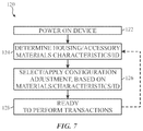
- FIG. 7 is a flow diagram describing a process 120 for dynamically configuring the radio frequency system 12 based upon housings 28 and/or accessories 29 of the electronic device 10 , in accordance with an embodiment.
- the process 120 begins with powering on the electronic device 10 (block 122 ). Once powered-on, a determination is made as to the particular housings 28 , accessories 29 , and/or housing 28 and/or accessory 29 characteristics that are currently present with the electronic device 10 (block 124 ). For example, firmware and/or a file (e.g., system configuration file) of the electronic device may indicate the particular housing 28 and/or housing 28 characteristic of the current device, as discussed above. Additionally and/or alternatively, user inputs (e.g., via the GUI 30 ) may indicate particular characteristics and/or identities of the housings 28 and/or accessories 29 . Further, in some embodiments, the accessories 29 may provide an indication of particular characteristics and/or identities of the accessories 29 .
- firmware and/or a file e.g., system configuration file
- user inputs e.g., via the GUI 30
- the accessories 29 may provide an indication of particular characteristics and/or identities of the accessories 29 .
- the proper radio frequency system 12 settings are selected and applied to the electronic device (block 126 ).
- the configuration adjustment logic 12 may be polled for settings associated with a particular identity (e.g., model number, etc.) of a housing 28 and/or electronic device 10 , an identity of an accessory 29 , and/or one or more characteristics of the housing 28 and/or electronic device 10 .
- the associated settings may be associated solely with the housing 28 , solely with the accessories 29 , or with the combination of the housing 28 and the accessories 29 .
- the electronic device 10 may re-determine the housings 28 and/or accessories 29 that are present (block 124 ) and select and apply new radio frequency system 12 settings when housing 28 and/or accessory modifications 29 are detected.
- blocks 124 - 128 may be re-implemented). In some embodiments, these steps may be completed on a periodic basis (e.g., every one hour, two hours, one day, one week, etc.).
- the technical effects of the present disclosure include improving performance of a radio frequency system by adjusting operation based at least in part on housings 28 and/or proximate accessories 29 of the electronic device 10 . More specifically, upon determination of particular housings 28 , accessories 29 , and/or combinations of housings 28 and/or 29 , radio frequency system 12 settings that are known to produce a sufficient communication experience may be applied to the radio frequency system 12 . In this manner, tailored operational parameters may be set, thereby improving efficiency and/or reliability, since the operational parameters may be dynamically adjusted for housings 28 and/or accessories 29 that might impact the radio frequency communications.
Landscapes
- Engineering & Computer Science (AREA)
- Computer Hardware Design (AREA)
- Theoretical Computer Science (AREA)
- General Engineering & Computer Science (AREA)
- Human Computer Interaction (AREA)
- Physics & Mathematics (AREA)
- General Physics & Mathematics (AREA)
- Telephone Function (AREA)
- Computer Networks & Wireless Communication (AREA)
- Signal Processing (AREA)
Abstract
Description
Claims (13)
Priority Applications (1)
| Application Number | Priority Date | Filing Date | Title |
|---|---|---|---|
| US14/641,135 US11150693B2 (en) | 2015-03-06 | 2015-03-06 | Adaptable radio frequency systems and methods |
Applications Claiming Priority (1)
| Application Number | Priority Date | Filing Date | Title |
|---|---|---|---|
| US14/641,135 US11150693B2 (en) | 2015-03-06 | 2015-03-06 | Adaptable radio frequency systems and methods |
Publications (2)
| Publication Number | Publication Date |
|---|---|
| US20160262028A1 US20160262028A1 (en) | 2016-09-08 |
| US11150693B2 true US11150693B2 (en) | 2021-10-19 |
Family
ID=56850067
Family Applications (1)
| Application Number | Title | Priority Date | Filing Date |
|---|---|---|---|
| US14/641,135 Active 2037-09-09 US11150693B2 (en) | 2015-03-06 | 2015-03-06 | Adaptable radio frequency systems and methods |
Country Status (1)
| Country | Link |
|---|---|
| US (1) | US11150693B2 (en) |
Families Citing this family (6)
| Publication number | Priority date | Publication date | Assignee | Title |
|---|---|---|---|---|
| US10127920B2 (en) | 2017-01-09 | 2018-11-13 | Google Llc | Acoustic parameter adjustment |
| US10691072B1 (en) * | 2017-09-11 | 2020-06-23 | Apple Inc. | Identification of bands for wearable electronic devices |
| WO2019140284A1 (en) | 2018-01-11 | 2019-07-18 | Access Solutions, LLC | Systems and methods for foreign material exclusion accountability |
| US10769933B2 (en) * | 2019-01-27 | 2020-09-08 | Iris Forbes | Safety wearable device |
| US11860588B1 (en) | 2020-03-13 | 2024-01-02 | Apple Inc. | Identification of watch bands |
| US12204292B1 (en) * | 2020-03-13 | 2025-01-21 | Apple Inc. | Identification of watch bands |
Citations (11)
| Publication number | Priority date | Publication date | Assignee | Title |
|---|---|---|---|---|
| US6012105A (en) * | 1997-05-01 | 2000-01-04 | Telefonaktiebolaget L M Ericsson | System for interfacing with an external accessory in one of two interface modes based on whether communication can be established with external accessory or not |
| US6477117B1 (en) * | 2000-06-30 | 2002-11-05 | International Business Machines Corporation | Alarm interface for a smart watch |
| US20030228891A1 (en) * | 2002-06-05 | 2003-12-11 | Nec Corporation | Mobile phone, analysis device included therein, and analysis method |
| US20040242289A1 (en) * | 2003-06-02 | 2004-12-02 | Roger Jellicoe | Configuration driven automatic antenna impedance matching |
| US20050009579A1 (en) * | 2003-07-08 | 2005-01-13 | Kuan-Hua Chen | Method for identifying detachable cover of a cellular phone |
| US20090040022A1 (en) * | 2004-06-28 | 2009-02-12 | Klaus Finkenzeller | Transponder Unit |
| US20120230299A1 (en) | 2009-11-27 | 2012-09-13 | Huawei Device Co., Ltd. | Method for Reconfiguring Micro Base Station and Corresponding Micro Base Station |
| US8442437B1 (en) | 2004-12-30 | 2013-05-14 | Cypress Semiconductor Corporation | Method and apparatus for binding wireless devices |
| US8738103B2 (en) | 2006-07-18 | 2014-05-27 | Fractus, S.A. | Multiple-body-configuration multimedia and smartphone multifunction wireless devices |
| US8786440B2 (en) | 2009-10-02 | 2014-07-22 | Checkpoint Systems, Inc. | Calibration of beamforming nodes in a configurable monitoring device system |
| US20150172426A1 (en) * | 2013-12-16 | 2015-06-18 | Motorola Mobility Llc | Antenna tuning correction for multiple rear housing materials |
-
2015
- 2015-03-06 US US14/641,135 patent/US11150693B2/en active Active
Patent Citations (11)
| Publication number | Priority date | Publication date | Assignee | Title |
|---|---|---|---|---|
| US6012105A (en) * | 1997-05-01 | 2000-01-04 | Telefonaktiebolaget L M Ericsson | System for interfacing with an external accessory in one of two interface modes based on whether communication can be established with external accessory or not |
| US6477117B1 (en) * | 2000-06-30 | 2002-11-05 | International Business Machines Corporation | Alarm interface for a smart watch |
| US20030228891A1 (en) * | 2002-06-05 | 2003-12-11 | Nec Corporation | Mobile phone, analysis device included therein, and analysis method |
| US20040242289A1 (en) * | 2003-06-02 | 2004-12-02 | Roger Jellicoe | Configuration driven automatic antenna impedance matching |
| US20050009579A1 (en) * | 2003-07-08 | 2005-01-13 | Kuan-Hua Chen | Method for identifying detachable cover of a cellular phone |
| US20090040022A1 (en) * | 2004-06-28 | 2009-02-12 | Klaus Finkenzeller | Transponder Unit |
| US8442437B1 (en) | 2004-12-30 | 2013-05-14 | Cypress Semiconductor Corporation | Method and apparatus for binding wireless devices |
| US8738103B2 (en) | 2006-07-18 | 2014-05-27 | Fractus, S.A. | Multiple-body-configuration multimedia and smartphone multifunction wireless devices |
| US8786440B2 (en) | 2009-10-02 | 2014-07-22 | Checkpoint Systems, Inc. | Calibration of beamforming nodes in a configurable monitoring device system |
| US20120230299A1 (en) | 2009-11-27 | 2012-09-13 | Huawei Device Co., Ltd. | Method for Reconfiguring Micro Base Station and Corresponding Micro Base Station |
| US20150172426A1 (en) * | 2013-12-16 | 2015-06-18 | Motorola Mobility Llc | Antenna tuning correction for multiple rear housing materials |
Also Published As
| Publication number | Publication date |
|---|---|
| US20160262028A1 (en) | 2016-09-08 |
Similar Documents
| Publication | Publication Date | Title |
|---|---|---|
| US11150693B2 (en) | Adaptable radio frequency systems and methods | |
| US10678495B2 (en) | Electronic apparatus and method for adjusting intensity of sound of an external device | |
| US9654154B2 (en) | Radio frequency adaptive voltage shaping power amplifier systems and methods | |
| US10716080B2 (en) | Calibration techniques for envelope tracking power amplifiers | |
| US10700743B2 (en) | Methods and apparatus for determining nearfield localization using phase and RSSI diversity | |
| US20190235475A1 (en) | Method and apparatus for controlling motor vibration | |
| KR102602693B1 (en) | Apparatus and method for providing efficient beamforming feedback | |
| KR101689941B1 (en) | Method and apparatus to prevent receiver desensitization from radiated hdmi signals in accessory or computing devices | |
| EP2903168B1 (en) | Apparatus and method for providing communication | |
| KR20190017138A (en) | Electronic device and method for controlling amplifier based on status of the electronic device | |
| KR20150094058A (en) | Frequency division duplex wireless receiver and method | |
| KR20190066810A (en) | Electronic device for controlling clock frequency and operating method thereof | |
| US11063735B2 (en) | Electronic device for reducing noise in frequency band of Rx signal and method for the same | |
| US9560601B2 (en) | Radio frequency system power back off systems and methods | |
| US10455392B2 (en) | Adaptive matching with antenna detuning detection | |
| US10523250B2 (en) | Systems and methods for mitigating intermodulation effects | |
| EP3142189B1 (en) | Antenna adjustment method based on variable capacitor, and corresponding apparatus | |
| US11025347B2 (en) | Compensating for channel distortion during contactless communication | |
| CN108039928B (en) | Received signal strength testing method, device, system and electronic equipment | |
| JP2017187363A (en) | Ota measurement method and ota measurement device | |
| CN103199943B (en) | The test macro of radio-frequency card reader and method | |
| US11012164B2 (en) | Systems and methods for radio frequency head validation via antenna coupling or signal reflection | |
| CN102810003B (en) | Driving intensity control device, method and terminal equipment | |
| CN108123762B (en) | Transmission power test method, device, system and electronic equipment | |
| US10666366B2 (en) | Reverse coupler for transceiver devices |
Legal Events
| Date | Code | Title | Description |
|---|---|---|---|
| AS | Assignment |
Owner name: APPLE INC., CALIFORNIA Free format text: ASSIGNMENT OF ASSIGNORS INTEREST;ASSIGNORS:REDDY, VUSTHLA SUNIL;ZENG, XINPING;AGBOH, PETER M.;AND OTHERS;SIGNING DATES FROM 20150304 TO 20150501;REEL/FRAME:035889/0564 |
|
| STPP | Information on status: patent application and granting procedure in general |
Free format text: TC RETURN OF APPEAL |
|
| STCV | Information on status: appeal procedure |
Free format text: ON APPEAL -- AWAITING DECISION BY THE BOARD OF APPEALS |
|
| STCV | Information on status: appeal procedure |
Free format text: BOARD OF APPEALS DECISION RENDERED |
|
| STPP | Information on status: patent application and granting procedure in general |
Free format text: NOTICE OF ALLOWANCE MAILED -- APPLICATION RECEIVED IN OFFICE OF PUBLICATIONS |
|
| STPP | Information on status: patent application and granting procedure in general |
Free format text: AWAITING TC RESP., ISSUE FEE NOT PAID |
|
| STPP | Information on status: patent application and granting procedure in general |
Free format text: NOTICE OF ALLOWANCE MAILED -- APPLICATION RECEIVED IN OFFICE OF PUBLICATIONS |
|
| STPP | Information on status: patent application and granting procedure in general |
Free format text: PUBLICATIONS -- ISSUE FEE PAYMENT VERIFIED |
|
| STPP | Information on status: patent application and granting procedure in general |
Free format text: AWAITING TC RESP, ISSUE FEE PAYMENT VERIFIED |
|
| STPP | Information on status: patent application and granting procedure in general |
Free format text: PUBLICATIONS -- ISSUE FEE PAYMENT VERIFIED |
|
| STCF | Information on status: patent grant |
Free format text: PATENTED CASE |
|
| MAFP | Maintenance fee payment |
Free format text: PAYMENT OF MAINTENANCE FEE, 4TH YEAR, LARGE ENTITY (ORIGINAL EVENT CODE: M1551); ENTITY STATUS OF PATENT OWNER: LARGE ENTITY Year of fee payment: 4 |