US11149990B2 - Gas wave refrigerator - Google Patents
Gas wave refrigerator Download PDFInfo
- Publication number
- US11149990B2 US11149990B2 US16/178,564 US201816178564A US11149990B2 US 11149990 B2 US11149990 B2 US 11149990B2 US 201816178564 A US201816178564 A US 201816178564A US 11149990 B2 US11149990 B2 US 11149990B2
- Authority
- US
- United States
- Prior art keywords
- nozzle
- main shaft
- disposed
- rotator
- gas
- Prior art date
- Legal status (The legal status is an assumption and is not a legal conclusion. Google has not performed a legal analysis and makes no representation as to the accuracy of the status listed.)
- Active, expires
Links
- 230000010355 oscillation Effects 0.000 claims abstract description 35
- 230000035939 shock Effects 0.000 claims description 14
- 238000010521 absorption reaction Methods 0.000 claims description 5
- 230000002457 bidirectional effect Effects 0.000 claims description 4
- 239000007921 spray Substances 0.000 claims description 3
- 239000010720 hydraulic oil Substances 0.000 abstract description 7
- 239000007789 gas Substances 0.000 description 64
- 230000006835 compression Effects 0.000 description 11
- 238000007906 compression Methods 0.000 description 11
- 230000003068 static effect Effects 0.000 description 7
- 239000003921 oil Substances 0.000 description 6
- 239000007787 solid Substances 0.000 description 6
- 238000001816 cooling Methods 0.000 description 4
- 238000010586 diagram Methods 0.000 description 4
- 239000010721 machine oil Substances 0.000 description 4
- 238000002347 injection Methods 0.000 description 3
- 239000007924 injection Substances 0.000 description 3
- 238000000034 method Methods 0.000 description 2
- 238000012986 modification Methods 0.000 description 2
- 230000004048 modification Effects 0.000 description 2
- 238000005057 refrigeration Methods 0.000 description 2
- 238000007789 sealing Methods 0.000 description 2
- 230000002411 adverse Effects 0.000 description 1
- 238000006243 chemical reaction Methods 0.000 description 1
- 230000007423 decrease Effects 0.000 description 1
- 239000007791 liquid phase Substances 0.000 description 1
- 239000012071 phase Substances 0.000 description 1
- 230000007704 transition Effects 0.000 description 1
Images


Classifications
-
- F—MECHANICAL ENGINEERING; LIGHTING; HEATING; WEAPONS; BLASTING
- F25—REFRIGERATION OR COOLING; COMBINED HEATING AND REFRIGERATION SYSTEMS; HEAT PUMP SYSTEMS; MANUFACTURE OR STORAGE OF ICE; LIQUEFACTION SOLIDIFICATION OF GASES
- F25B—REFRIGERATION MACHINES, PLANTS OR SYSTEMS; COMBINED HEATING AND REFRIGERATION SYSTEMS; HEAT PUMP SYSTEMS
- F25B9/00—Compression machines, plants or systems, in which the refrigerant is air or other gas of low boiling point
- F25B9/02—Compression machines, plants or systems, in which the refrigerant is air or other gas of low boiling point using Joule-Thompson effect; using vortex effect
-
- F—MECHANICAL ENGINEERING; LIGHTING; HEATING; WEAPONS; BLASTING
- F25—REFRIGERATION OR COOLING; COMBINED HEATING AND REFRIGERATION SYSTEMS; HEAT PUMP SYSTEMS; MANUFACTURE OR STORAGE OF ICE; LIQUEFACTION SOLIDIFICATION OF GASES
- F25B—REFRIGERATION MACHINES, PLANTS OR SYSTEMS; COMBINED HEATING AND REFRIGERATION SYSTEMS; HEAT PUMP SYSTEMS
- F25B9/00—Compression machines, plants or systems, in which the refrigerant is air or other gas of low boiling point
- F25B9/14—Compression machines, plants or systems, in which the refrigerant is air or other gas of low boiling point characterised by the cycle used, e.g. Stirling cycle
- F25B9/145—Compression machines, plants or systems, in which the refrigerant is air or other gas of low boiling point characterised by the cycle used, e.g. Stirling cycle pulse-tube cycle
-
- F—MECHANICAL ENGINEERING; LIGHTING; HEATING; WEAPONS; BLASTING
- F25—REFRIGERATION OR COOLING; COMBINED HEATING AND REFRIGERATION SYSTEMS; HEAT PUMP SYSTEMS; MANUFACTURE OR STORAGE OF ICE; LIQUEFACTION SOLIDIFICATION OF GASES
- F25B—REFRIGERATION MACHINES, PLANTS OR SYSTEMS; COMBINED HEATING AND REFRIGERATION SYSTEMS; HEAT PUMP SYSTEMS
- F25B1/00—Compression machines, plants or systems with non-reversible cycle
- F25B1/10—Compression machines, plants or systems with non-reversible cycle with multi-stage compression
-
- F—MECHANICAL ENGINEERING; LIGHTING; HEATING; WEAPONS; BLASTING
- F25—REFRIGERATION OR COOLING; COMBINED HEATING AND REFRIGERATION SYSTEMS; HEAT PUMP SYSTEMS; MANUFACTURE OR STORAGE OF ICE; LIQUEFACTION SOLIDIFICATION OF GASES
- F25B—REFRIGERATION MACHINES, PLANTS OR SYSTEMS; COMBINED HEATING AND REFRIGERATION SYSTEMS; HEAT PUMP SYSTEMS
- F25B13/00—Compression machines, plants or systems, with reversible cycle
-
- F—MECHANICAL ENGINEERING; LIGHTING; HEATING; WEAPONS; BLASTING
- F25—REFRIGERATION OR COOLING; COMBINED HEATING AND REFRIGERATION SYSTEMS; HEAT PUMP SYSTEMS; MANUFACTURE OR STORAGE OF ICE; LIQUEFACTION SOLIDIFICATION OF GASES
- F25B—REFRIGERATION MACHINES, PLANTS OR SYSTEMS; COMBINED HEATING AND REFRIGERATION SYSTEMS; HEAT PUMP SYSTEMS
- F25B25/00—Machines, plants or systems, using a combination of modes of operation covered by two or more of the groups F25B1/00 - F25B23/00
- F25B25/005—Machines, plants or systems, using a combination of modes of operation covered by two or more of the groups F25B1/00 - F25B23/00 using primary and secondary systems
-
- F—MECHANICAL ENGINEERING; LIGHTING; HEATING; WEAPONS; BLASTING
- F25—REFRIGERATION OR COOLING; COMBINED HEATING AND REFRIGERATION SYSTEMS; HEAT PUMP SYSTEMS; MANUFACTURE OR STORAGE OF ICE; LIQUEFACTION SOLIDIFICATION OF GASES
- F25B—REFRIGERATION MACHINES, PLANTS OR SYSTEMS; COMBINED HEATING AND REFRIGERATION SYSTEMS; HEAT PUMP SYSTEMS
- F25B41/00—Fluid-circulation arrangements
- F25B41/30—Expansion means; Dispositions thereof
- F25B41/37—Capillary tubes
-
- F—MECHANICAL ENGINEERING; LIGHTING; HEATING; WEAPONS; BLASTING
- F25—REFRIGERATION OR COOLING; COMBINED HEATING AND REFRIGERATION SYSTEMS; HEAT PUMP SYSTEMS; MANUFACTURE OR STORAGE OF ICE; LIQUEFACTION SOLIDIFICATION OF GASES
- F25B—REFRIGERATION MACHINES, PLANTS OR SYSTEMS; COMBINED HEATING AND REFRIGERATION SYSTEMS; HEAT PUMP SYSTEMS
- F25B9/00—Compression machines, plants or systems, in which the refrigerant is air or other gas of low boiling point
-
- F—MECHANICAL ENGINEERING; LIGHTING; HEATING; WEAPONS; BLASTING
- F25—REFRIGERATION OR COOLING; COMBINED HEATING AND REFRIGERATION SYSTEMS; HEAT PUMP SYSTEMS; MANUFACTURE OR STORAGE OF ICE; LIQUEFACTION SOLIDIFICATION OF GASES
- F25B—REFRIGERATION MACHINES, PLANTS OR SYSTEMS; COMBINED HEATING AND REFRIGERATION SYSTEMS; HEAT PUMP SYSTEMS
- F25B2309/00—Gas cycle refrigeration machines
- F25B2309/14—Compression machines, plants or systems characterised by the cycle used
- F25B2309/1418—Pulse-tube cycles with valves in gas supply and return lines
-
- F—MECHANICAL ENGINEERING; LIGHTING; HEATING; WEAPONS; BLASTING
- F25—REFRIGERATION OR COOLING; COMBINED HEATING AND REFRIGERATION SYSTEMS; HEAT PUMP SYSTEMS; MANUFACTURE OR STORAGE OF ICE; LIQUEFACTION SOLIDIFICATION OF GASES
- F25B—REFRIGERATION MACHINES, PLANTS OR SYSTEMS; COMBINED HEATING AND REFRIGERATION SYSTEMS; HEAT PUMP SYSTEMS
- F25B2500/00—Problems to be solved
- F25B2500/12—Sound
-
- F—MECHANICAL ENGINEERING; LIGHTING; HEATING; WEAPONS; BLASTING
- F25—REFRIGERATION OR COOLING; COMBINED HEATING AND REFRIGERATION SYSTEMS; HEAT PUMP SYSTEMS; MANUFACTURE OR STORAGE OF ICE; LIQUEFACTION SOLIDIFICATION OF GASES
- F25B—REFRIGERATION MACHINES, PLANTS OR SYSTEMS; COMBINED HEATING AND REFRIGERATION SYSTEMS; HEAT PUMP SYSTEMS
- F25B2700/00—Sensing or detecting of parameters; Sensors therefor
- F25B2700/19—Pressures
- F25B2700/193—Pressures of the compressor
- F25B2700/1931—Discharge pressures
Definitions
- This disclosure relates to a gas wave refrigerator (GWR), which is a device that refrigerates a medium by shock waves or expansion waves generated by gas pressure energy.
- GWR gas wave refrigerator
- Conventional gas wave refrigerators include a plurality of rotational components and sealing elements, so they have complex structures and are difficult to assemble and disassemble.
- the gas wave refrigerator comprises a two-row-nozzle rotator and two rows of oscillation receiving tubes.
- the gas wave refrigerator comprises a first end body; a second end body; a main body disposed between the first end body and the second end body; a first end cover; a hydraulic mandrel; a hydraulic oil inlet pipe; a hydraulic cylinder; a first single mechanical seal; a bushing; a nozzle rotator comprising a first row of nozzles and a second row of nozzles; press plates disposed at two sides of the nozzle rotator; a main shaft; oscillation receiving tubes; a belt wheel; an embedded bearing seat; a second end cover; and a hydraulic balance device, the hydraulic balance device comprising a hydraulic cylinder, a hydraulic mandrel, a seal ring, bearings, a piston, and a piston ring.
- the outer walls of the first end body, the main body, and the second end body form a shell of the gas wave refrigerator;
- the main shaft is disposed in the main body and comprises a first half shaft which is solid and a second half shaft which is hollow;
- the nozzle rotator is in a cylindrical shape;
- the nozzle rotator and the press plates disposed at two sides of the nozzle rotator are installed on the main shaft;
- the nozzle rotator is sandwiched by the two press plates;
- the first row of nozzles and the second row of nozzles are disposed circumferentially on the lateral surface of the nozzle rotator;
- nozzle exits of the first row of nozzles are aligned with or staggered from nozzle exits of the second row of nozzles at an axial direction of the nozzle rotator;
- the oscillation receiving tubes are disposed on the main body in two rows corresponding to the first row of nozzles and the second row of nozzles, respectively; when in use, the
- the nozzle exits of the nozzle rotator can be circular, square, or rectangular, and can be between 1 and 9 in number; the nozzle exits of the nozzle rotator can communicate with pipe holes of the oscillation receiving tubes on the main body; each row of the nozzles can communicate with 20-130 oscillation receiving tubes, and the tail of each oscillation receiving tube can be connected to one shock absorption cavity; the main body can comprise one gas inlet pipe and one to ten exhaust pipes, and the exhaust pipes can be arranged on two sides of the nozzle rotator; the diameters of the pipe holes matching the nozzle rotator on the main body can be between 5 and 55 mm; the deflection angles of the pipe holes can be between 0 and 25 degrees; and the lengths of the oscillation receiving tubes fixed on the pipe holes can be between 1500 and 12000 mm.
- the axial force is balanced by the hydraulic balance device, which prolongs the service life of the gas wave refrigerator.
- the hydraulic balance device, the bearings, and the single mechanical seals can share one machine oil circulating system, simplifying the structure of the machine.
- the main shaft is integrated with the spiral seals, reducing the assembly steps.
- the gas wave refrigerator includes mechanical seals which exhibit improved sealing efficiency.
- the embedded bearing seat and the hydraulic cylinder are arranged on two ends of the machine body, which facilitates the disassembly and replacement of the gas wave refrigerator.
- FIG. 1 is a schematic diagram of a gas wave refrigerator as described in the disclosure
- FIG. 2 is a schematic diagram of a first end body of a gas wave refrigerator as described in the disclosure
- FIG. 3 is a schematic diagram of a second end body of a gas wave refrigerator as described in the disclosure.
- FIG. 5 is a schematic diagram of a nozzle rotator of a gas wave refrigerator as described in the disclosure
- FIG. 6 is a front view of a nozzle rotator as described in the disclosure.
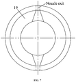
- FIG. 7 is a sectional view taken from arrow VII in FIG. 6 ;
- FIG. 8 is a sectional view taken from arrow VIII in FIG. 6 ;
- FIG. 9 is a front view of a press plate of a nozzle rotator as described in the disclosure.
- FIG. 10 is a side view of a press plate of a nozzle rotator as described in the disclosure.
- FIGS. 1-4 illustrate a gas wave refrigerator comprising a first end body 1 , a first end cover 2 , a hydraulic mandrel 3 , a hydraulic oil inlet pipe 4 , a hydraulic cylinder 5 , a main body 16 , a first single mechanical seal 17 , a nozzle rotator 19 , a bushing 20 , press plates 21 disposed at two sides of the nozzle rotator 19 , a main shaft 22 , oscillation receiving tubes 28 , a belt wheel 29 , a second end body 35 , an embedded bearing seat 38 , a second end cover 40 .
- the gas wave refrigerator is of a horizontal structure.
- the main body 16 is deposed between the first end body 1 and the second end body 35 .
- the second end body 35 comprises a speed measuring sensor 31 .
- the outer walls of the first end body 1 , the main body 16 , and the second end body 35 form the shell of the gas wave refrigerator.
- the shell plus the first end cover 2 and the second end cover 40 form the entire housing of the gas wave refrigerator.
- the main shaft 22 is disposed in the main body and comprises a first half shaft which is solid and a second half shaft which is hollow.
- the nozzle rotator 19 and the press plates 21 disposed at two sides of the nozzle rotator 19 are installed on the main shaft 22 . Each nozzle rotator 19 is sandwiched by two press plates 21 .
- the nozzle exits of the first row of nozzles on the nozzle rotator are aligned with or staggered from nozzle exits of the second row of nozzles at an axial direction of the nozzle rotator.
- the nozzle rotator 19 rotates synchronously along with the main shaft 22 , and continuously sprays gas into corresponding double row oscillation receiving tubes 28 .
- the raw gas enters the hollow half shaft of the main shaft 22 via a gas inlet pipe 44 and the second end cover 40 , and then is sprayed outwards via the nozzle exits of the nozzle rotator 19 .
- the main shaft 22 is equipped with different seal parts as needed.
- the inlet of the hollow half shaft of the main shaft 22 is provided with a second single mechanical seal 34 .
- the gas enters the machine in the axial direction, so that the second bearings 12 are subject to the vast majority of stress, which adversely affects the service life of the bearings.
- a hydraulic balance force is exerted on the solid half shaft of the main shaft to counteract the axial force.
- a hydraulic balance device is disposed close to the first half shaft of the main shaft 22 .
- the hydraulic balance device comprises a hydraulic cylinder 5 , a hydraulic mandrel 3 , a seal ring 6 , first bearings 7 , a piston 8 , and a piston ring 9 .
- the piston 8 and the piston ring 9 are disposed between the first bearings 7 .
- the hydraulic mandrel 3 is disposed in the hydraulic cylinder 5 and is supported by the first bearings 7 .
- the top of the hydraulic mandrel 3 butts against the center of the solid half shaft of the main shaft 22 .
- the hydraulic cylinder 5 as a component is embedded into one end of the first end body 1 , and then is sealed by the first end cover 2 .
- the hydraulic oil stored in an oil tank 50 is pumped into the hydraulic balance device via the oil pump 49 , so that the piston produces a pushing force to the other end.
- the pushing force and the axial force are opposite in directions and counteract with each other.
- the belt wheel and speed measuring gears are arranged in the middle of the main shaft, and the motor 45 is disposed in the middle of the gas wave refrigerator and drives the main shaft to rotate via the belt 30 and the belt wheel. To prevent the gas leakage, two sides of the belt wheel should be sealed.
- the nozzle rotator 19 , the exhaust pipes 26 , and the belt wheel 29 adopt radial labyrinth seals;
- the radial labyrinth seals are formed by a movable seal ring 23 , a static seal ring 24 , and a first O-shaped ring 25 ;
- the movable seal ring 23 is fixed on the main shaft 22 ;
- an outer circle of the static seal ring 24 sleeves the main body 16 ;
- the first O-shaped ring 25 is disposed between the movable seal ring 23 and the static seal ring 24 .
- the two second bearings 12 serving as the support of the main shaft 22 inside the machine body, are arranged at two ends of the main shaft, respectively, and are fixed by an outer compression cap 11 and an inner compression nut 10 .
- the bearing boxes are arranged on two ends of the gas wave refrigerator, respectively.
- One bearing box is disposed in the first end body 1
- the other bearing box is in the form of an embedded bearing seat 38 in the second end body.
- the machine oil of the hydraulic balance device in the first end body can lubricate the second bearings.
- bidirectional spiral seals 22 a are arranged on the main shaft between the second bearings and the gas path system.
- a first single mechanical seal 17 is arranged on the main shaft close to the gas outlet.
- One end of the first single mechanical seal is provided with a seal cover.
- the circumference of the outer circle of the shell of the gas wave refrigerator is provided with three screw holes in one plane, the included angles between each two of which are 120°.
- the seal cover is fixed by three tapered threaded bolts 48 corresponding to the three screw holes.
- the hydraulic oil inlet pipe 4 is an oil input pipe of the hydraulic balance device and is soldered on the first end cover 2 .
- the hydraulic oil inlet pipe 4 is connected to the first end body 1 via a first movable joint 13 .
- the first end body 1 is connected to the main body 16 via a first double-end stud 14 .
- the second O-shaped seal ring 15 is disposed between the first end body 1 and the main body 16 .
- the bushing 20 is a transition piece of the main body 16 and the nozzle rotator 19 .
- the second end body 35 comprises a second movable joint 33 .
- a second compression nut 37 is provided to tighten the nut of the third bearings 36 of the second end body.
- the third O-shaped seal ring 39 is embedded between the embedded bearing seat 38 in the second end body and the second end body 35 .
- the second double-end stud 41 is a fastening bolt between the second end cover 40 and the second end body 35 .
- the third movable joint 43 is an oil injection joint of the third bearings 36 .
- the pipe joint 46 is a connection joint of the main body 16 and the oscillation receiving tubes 28 .
- the second O-shaped ring 47 is a seal ring between the press plate 21 and the nozzle rotator 19 .
- FIGS. 5-10 illustrate structural drawings of the nozzle rotator of the gas wave refrigerator.
- the nozzle exits of the nozzle rotator 19 are circular, square, or rectangular, and are between 1 and 9 in number.
- the nozzle exits of the nozzle rotator communicate with pipe holes of the oscillation receiving tubes on the main body.
- Each row of the nozzles communicates with 20-130 oscillation receiving tubes, and the tail of each oscillation receiving tube is connected to one shock absorption cavity 42 .
- the main body comprises one gas inlet pipe and one to ten exhaust pipes 26 , and the exhaust pipes are arranged on two sides of the nozzle rotator 19 .
- the diameters of the pipe holes matching the nozzle rotator 19 on the main body 16 are 5 to 55 mm, the deflection angles of the pipe holes are 0 to 25 degrees, and the lengths of the oscillation receiving tubes fixedly connected onto the pipe holes are 1500 to 12000 mm.
- the working principle of the oscillation receiving tubes are summarized as follows: in operation, when the gas is injected into the oscillation receiving tubes, compression waves, shock waves, expansion waves, and reflection shock waves will be generated and move in the tubes constantly. The movement of the waves in each pipe is the same. The gas in the tube is exhausted outward during two injection intervals. The movement of the compression wave and shock wave in the tube increases the temperature of the gas in the tube. The heat is dissipated through the tube wall and the produced expansion wave cools the gas. This is because the pressure gas does work through expansion and reduces the energy, thus cooling down itself.
- Injection stage when a high-speed gas is injected into the oscillating receiving tube, a contact surface is formed between the injected fresh gas and the original stagnant gas in the tube.
- the contact surface can be regarded as a “piston” without mass. Since the speed and pressure are not equal on both sides of the contact surface, to meet the compatibility conditions of the contact surface (i.e., the speed and pressure of the gases on both sides of the contact surface must be equal), the forward movement of the “piston” means that the compression wave is continuously pushed forward, a shock wave will appear in front of the “piston” and moves in the same direction as that of the “piston.” The shock wave is the result of the compression wave superposition.
- the tail of each oscillation receiving tube is provided with one shock absorption cavity.
Landscapes
- Engineering & Computer Science (AREA)
- Physics & Mathematics (AREA)
- Mechanical Engineering (AREA)
- Thermal Sciences (AREA)
- General Engineering & Computer Science (AREA)
- Structures Of Non-Positive Displacement Pumps (AREA)
- Joints Allowing Movement (AREA)
- Drying Of Solid Materials (AREA)
Abstract
Description
Claims (2)
Applications Claiming Priority (2)
| Application Number | Priority Date | Filing Date | Title |
|---|---|---|---|
| CN201711111918.3A CN107843021B (en) | 2017-11-13 | 2017-11-13 | A double-layer nozzle and double-row tube gas-wave refrigerator with built-in drive hydraulic balance |
| CN201711111918.3 | 2017-11-13 |
Publications (2)
| Publication Number | Publication Date |
|---|---|
| US20190162452A1 US20190162452A1 (en) | 2019-05-30 |
| US11149990B2 true US11149990B2 (en) | 2021-10-19 |
Family
ID=61681609
Family Applications (1)
| Application Number | Title | Priority Date | Filing Date |
|---|---|---|---|
| US16/178,564 Active 2039-11-16 US11149990B2 (en) | 2017-11-13 | 2018-11-01 | Gas wave refrigerator |
Country Status (5)
| Country | Link |
|---|---|
| US (1) | US11149990B2 (en) |
| JP (1) | JP6841787B2 (en) |
| KR (1) | KR102008217B1 (en) |
| CN (1) | CN107843021B (en) |
| WO (1) | WO2019091229A1 (en) |
Families Citing this family (5)
| Publication number | Priority date | Publication date | Assignee | Title |
|---|---|---|---|---|
| CN107843021B (en) * | 2017-11-13 | 2019-07-30 | 大连理工大学 | A double-layer nozzle and double-row tube gas-wave refrigerator with built-in drive hydraulic balance |
| GB2584441A (en) * | 2019-06-03 | 2020-12-09 | Fenomark Diagnostics Ab | Medical uses, methods and uses |
| CN114111081A (en) * | 2021-12-26 | 2022-03-01 | 大连理工大学 | Curved channel thermal-insulation type gas wave refrigerator |
| CN114216279B (en) * | 2021-12-26 | 2022-09-06 | 大连理工大学 | A forced water-cooled and heat-insulated double-layer oscillating tube gas-wave refrigerator |
| CN115420030B (en) * | 2022-09-14 | 2023-11-07 | 大连理工大学 | Rotary nozzle type air wave refrigerator with driving blade structure |
Citations (2)
| Publication number | Priority date | Publication date | Assignee | Title |
|---|---|---|---|---|
| CN100575900C (en) * | 2005-12-30 | 2009-12-30 | 大连理工大学 | A multifunctional gas wave cooling jet flow field display device and measurement method |
| CN103868269A (en) * | 2014-03-28 | 2014-06-18 | 大连理工大学 | A contact sealed inverted gas wave refrigerator |
Family Cites Families (10)
| Publication number | Priority date | Publication date | Assignee | Title |
|---|---|---|---|---|
| US4449895A (en) * | 1980-12-23 | 1984-05-22 | Matsushita Reiki Co., Ltd. | Refrigerant compressor |
| CN2274743Y (en) | 1996-01-12 | 1998-02-18 | 大连理工大学 | Air wave refrigeration natural gas dewatering apparatus |
| CN1085824C (en) | 1996-01-12 | 2002-05-29 | 大连理工大学 | Multi-stage gas wave refrigerator |
| CN101586889A (en) * | 2009-05-22 | 2009-11-25 | 深圳市力科气动科技有限公司 | Distributor rotor for gas wave regrigerator and gas wave regrigerator |
| CN201503162U (en) | 2009-05-22 | 2010-06-09 | 深圳市力科气动科技有限公司 | Gas wave refrigerator |
| CN101762110B (en) | 2010-02-06 | 2012-09-12 | 大连理工大学 | Mixed containing cavity heat dissipation gas wave refrigerating machine |
| CN103791646B (en) | 2014-02-24 | 2016-03-02 | 大连理工大学 | Drainage balanced top-mounted built-in gas wave refrigerator |
| CN203785309U (en) * | 2014-03-28 | 2014-08-20 | 大连理工大学 | Inverted gas wave refrigerator composed of multiple contact seals |
| CN207527868U (en) * | 2017-11-13 | 2018-06-22 | 大连理工大学 | Built-in driving balance type air wave machine with double-layer nozzle double-row oscillating tube |
| CN107843021B (en) * | 2017-11-13 | 2019-07-30 | 大连理工大学 | A double-layer nozzle and double-row tube gas-wave refrigerator with built-in drive hydraulic balance |
-
2017
- 2017-11-13 CN CN201711111918.3A patent/CN107843021B/en active Active
-
2018
- 2018-03-19 KR KR1020180031679A patent/KR102008217B1/en active Active
- 2018-04-13 JP JP2018077323A patent/JP6841787B2/en active Active
- 2018-09-20 WO PCT/CN2018/106612 patent/WO2019091229A1/en not_active Ceased
- 2018-11-01 US US16/178,564 patent/US11149990B2/en active Active
Patent Citations (2)
| Publication number | Priority date | Publication date | Assignee | Title |
|---|---|---|---|---|
| CN100575900C (en) * | 2005-12-30 | 2009-12-30 | 大连理工大学 | A multifunctional gas wave cooling jet flow field display device and measurement method |
| CN103868269A (en) * | 2014-03-28 | 2014-06-18 | 大连理工大学 | A contact sealed inverted gas wave refrigerator |
Also Published As
| Publication number | Publication date |
|---|---|
| KR102008217B1 (en) | 2019-10-23 |
| CN107843021B (en) | 2019-07-30 |
| JP6841787B2 (en) | 2021-03-10 |
| CN107843021A (en) | 2018-03-27 |
| JP2019090599A (en) | 2019-06-13 |
| US20190162452A1 (en) | 2019-05-30 |
| WO2019091229A1 (en) | 2019-05-16 |
| KR20190054873A (en) | 2019-05-22 |
Similar Documents
| Publication | Publication Date | Title |
|---|---|---|
| US11149990B2 (en) | Gas wave refrigerator | |
| JP5592933B2 (en) | Reaction turbine | |
| JP5769332B2 (en) | Scroll expander | |
| US12226785B2 (en) | Vacuum chamber structure of ultra-high gravity geotechnical centrifuge device | |
| CN101571326B (en) | Gas wave refrigerator | |
| CN101290174A (en) | Dissipative gas wave refrigerator with outer circulation | |
| KR101052253B1 (en) | Reaction turbine | |
| AU2013302217B2 (en) | Turbine assembly | |
| CA1039620A (en) | Rotary flow control valve | |
| CN103868269B (en) | A contact sealed inverted gas wave refrigerator | |
| CN203785309U (en) | Inverted gas wave refrigerator composed of multiple contact seals | |
| CN101586889A (en) | Distributor rotor for gas wave regrigerator and gas wave regrigerator | |
| CN101614456B (en) | Roller evaporator of snow making machine | |
| CN206694561U (en) | A kind of special labyrinth gland of spray cooling system | |
| US2841362A (en) | Multistage turbine | |
| CN207527868U (en) | Built-in driving balance type air wave machine with double-layer nozzle double-row oscillating tube | |
| CN104673400A (en) | Spiral slag cooler for high-temperature high-pressure gasifiers | |
| CN201503162U (en) | Gas wave refrigerator | |
| CN101270931A (en) | Damping hedging gas wave refrigerator | |
| RU2113639C1 (en) | Regenerating hydraulic pulsator | |
| CN201724463U (en) | Gas wave refrigerator | |
| CN201514072U (en) | Receiving tube used on gas wave refrigerator and gas wave refrigerator | |
| CN220687412U (en) | Steam turbine bearing box prevents into water vapour device | |
| CN201503163U (en) | Rotating-wheel distributor for gas wave refrigerating machine and gas wave refrigerating machine | |
| CN103791646A (en) | Drainage balanced top-mounted built-in gas wave refrigerator |
Legal Events
| Date | Code | Title | Description |
|---|---|---|---|
| AS | Assignment |
Owner name: DALIAN UNIVERSITY OF TECHNOLOGY, CHINA Free format text: ASSIGNMENT OF ASSIGNORS INTEREST;ASSIGNORS:HU, DAPENG;ZHU, CHE;DAI, YUQIANG;AND OTHERS;REEL/FRAME:047389/0553 Effective date: 20181101 |
|
| FEPP | Fee payment procedure |
Free format text: ENTITY STATUS SET TO UNDISCOUNTED (ORIGINAL EVENT CODE: BIG.); ENTITY STATUS OF PATENT OWNER: SMALL ENTITY |
|
| FEPP | Fee payment procedure |
Free format text: ENTITY STATUS SET TO SMALL (ORIGINAL EVENT CODE: SMAL); ENTITY STATUS OF PATENT OWNER: SMALL ENTITY |
|
| STPP | Information on status: patent application and granting procedure in general |
Free format text: DOCKETED NEW CASE - READY FOR EXAMINATION |
|
| STPP | Information on status: patent application and granting procedure in general |
Free format text: NON FINAL ACTION MAILED |
|
| STPP | Information on status: patent application and granting procedure in general |
Free format text: RESPONSE TO NON-FINAL OFFICE ACTION ENTERED AND FORWARDED TO EXAMINER |
|
| STPP | Information on status: patent application and granting procedure in general |
Free format text: NOTICE OF ALLOWANCE MAILED -- APPLICATION RECEIVED IN OFFICE OF PUBLICATIONS |
|
| STPP | Information on status: patent application and granting procedure in general |
Free format text: PUBLICATIONS -- ISSUE FEE PAYMENT VERIFIED |
|
| STCF | Information on status: patent grant |
Free format text: PATENTED CASE |
|
| MAFP | Maintenance fee payment |
Free format text: PAYMENT OF MAINTENANCE FEE, 4TH YR, SMALL ENTITY (ORIGINAL EVENT CODE: M2551); ENTITY STATUS OF PATENT OWNER: SMALL ENTITY Year of fee payment: 4 |