US11149955B2 - Modular forced air burner assembly - Google Patents
Modular forced air burner assembly Download PDFInfo
- Publication number
- US11149955B2 US11149955B2 US16/398,911 US201916398911A US11149955B2 US 11149955 B2 US11149955 B2 US 11149955B2 US 201916398911 A US201916398911 A US 201916398911A US 11149955 B2 US11149955 B2 US 11149955B2
- Authority
- US
- United States
- Prior art keywords
- coupled
- tube
- frame
- pipe
- coupler
- Prior art date
- Legal status (The legal status is an assumption and is not a legal conclusion. Google has not performed a legal analysis and makes no representation as to the accuracy of the status listed.)
- Active, expires
Links
Images


Classifications
-
- F—MECHANICAL ENGINEERING; LIGHTING; HEATING; WEAPONS; BLASTING
- F24—HEATING; RANGES; VENTILATING
- F24C—DOMESTIC STOVES OR RANGES ; DETAILS OF DOMESTIC STOVES OR RANGES, OF GENERAL APPLICATION
- F24C3/00—Stoves or ranges for gaseous fuels
- F24C3/02—Stoves or ranges for gaseous fuels with heat produced solely by flame
-
- F—MECHANICAL ENGINEERING; LIGHTING; HEATING; WEAPONS; BLASTING
- F23—COMBUSTION APPARATUS; COMBUSTION PROCESSES
- F23D—BURNERS
- F23D14/00—Burners for combustion of a gas, e.g. of a gas stored under pressure as a liquid
- F23D14/02—Premix gas burners, i.e. in which gaseous fuel is mixed with combustion air upstream of the combustion zone
-
- F—MECHANICAL ENGINEERING; LIGHTING; HEATING; WEAPONS; BLASTING
- F23—COMBUSTION APPARATUS; COMBUSTION PROCESSES
- F23D—BURNERS
- F23D14/00—Burners for combustion of a gas, e.g. of a gas stored under pressure as a liquid
- F23D14/46—Details
- F23D14/70—Baffles or like flow-disturbing devices
-
- F—MECHANICAL ENGINEERING; LIGHTING; HEATING; WEAPONS; BLASTING
- F23—COMBUSTION APPARATUS; COMBUSTION PROCESSES
- F23M—CASINGS, LININGS, WALLS OR DOORS SPECIALLY ADAPTED FOR COMBUSTION CHAMBERS, e.g. FIREBRIDGES; DEVICES FOR DEFLECTING AIR, FLAMES OR COMBUSTION PRODUCTS IN COMBUSTION CHAMBERS; SAFETY ARRANGEMENTS SPECIALLY ADAPTED FOR COMBUSTION APPARATUS; DETAILS OF COMBUSTION CHAMBERS, NOT OTHERWISE PROVIDED FOR
- F23M9/00—Baffles or deflectors for air or combustion products; Flame shields
- F23M9/02—Baffles or deflectors for air or combustion products; Flame shields in air inlets
-
- F—MECHANICAL ENGINEERING; LIGHTING; HEATING; WEAPONS; BLASTING
- F24—HEATING; RANGES; VENTILATING
- F24C—DOMESTIC STOVES OR RANGES ; DETAILS OF DOMESTIC STOVES OR RANGES, OF GENERAL APPLICATION
- F24C15/00—Details
- F24C15/32—Arrangements of ducts for hot gases, e.g. in or around baking ovens
- F24C15/322—Arrangements of ducts for hot gases, e.g. in or around baking ovens with forced circulation
-
- A—HUMAN NECESSITIES
- A47—FURNITURE; DOMESTIC ARTICLES OR APPLIANCES; COFFEE MILLS; SPICE MILLS; SUCTION CLEANERS IN GENERAL
- A47J—KITCHEN EQUIPMENT; COFFEE MILLS; SPICE MILLS; APPARATUS FOR MAKING BEVERAGES
- A47J2201/00—Devices having a modular construction
-
- F—MECHANICAL ENGINEERING; LIGHTING; HEATING; WEAPONS; BLASTING
- F23—COMBUSTION APPARATUS; COMBUSTION PROCESSES
- F23L—SUPPLYING AIR OR NON-COMBUSTIBLE LIQUIDS OR GASES TO COMBUSTION APPARATUS IN GENERAL ; VALVES OR DAMPERS SPECIALLY ADAPTED FOR CONTROLLING AIR SUPPLY OR DRAUGHT IN COMBUSTION APPARATUS; INDUCING DRAUGHT IN COMBUSTION APPARATUS; TOPS FOR CHIMNEYS OR VENTILATING SHAFTS; TERMINALS FOR FLUES
- F23L5/00—Blast-producing apparatus before the fire
- F23L5/02—Arrangements of fans or blowers
-
- F—MECHANICAL ENGINEERING; LIGHTING; HEATING; WEAPONS; BLASTING
- F23—COMBUSTION APPARATUS; COMBUSTION PROCESSES
- F23M—CASINGS, LININGS, WALLS OR DOORS SPECIALLY ADAPTED FOR COMBUSTION CHAMBERS, e.g. FIREBRIDGES; DEVICES FOR DEFLECTING AIR, FLAMES OR COMBUSTION PRODUCTS IN COMBUSTION CHAMBERS; SAFETY ARRANGEMENTS SPECIALLY ADAPTED FOR COMBUSTION APPARATUS; DETAILS OF COMBUSTION CHAMBERS, NOT OTHERWISE PROVIDED FOR
- F23M9/00—Baffles or deflectors for air or combustion products; Flame shields
- F23M9/04—Baffles or deflectors for air or combustion products; Flame shields with air supply passages in the baffle or shield
Definitions
- the disclosure and prior art relate to burner assemblies and more particularly pertains to a new burner assembly for rapidly heating contents of an oversized pot.
- An embodiment of the disclosure meets the needs presented above by generally comprising a frame, which has a top is substantially open and configured to support a pot.
- a burner assembly that is selectively positionable below the pot is configured to burn a fuel gas to heat the pot and its contents.
- a forced air module that is selectively operationally couplable to the burner assembly is configured to force air into the burner assembly to enhance combustion of the fuel gas.
- a pipe is selectively couplable to an exterior of the frame so that the pipe extends from proximate to a midpoint of the frame past the top of the frame. The pipe is configured to direct heat across a sidewall of the pot to enhance heating of the pot and its contents.
- FIG. 1 is an isometric perspective view of a modular forced air burner assembly according to an embodiment of the disclosure.
- FIG. 2 is an exploded view of an embodiment of the disclosure.
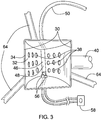
- FIG. 3 is a top view of a burner assembly of an embodiment of the disclosure.
- FIG. 4 is an in-use view of an embodiment of the disclosure.
- FIGS. 1 through 4 a new burner assembly embodying the principles and concepts of an embodiment of the disclosure and generally designated by the reference numeral 10 will be described.
- the modular forced air burner assembly 10 generally comprises a frame 12 , which has a top 14 is substantially open and configured to support a pot.
- the frame 12 comprises a plurality of legs 16 and a plurality of crossbars 18 .
- Each crossbar 18 is coupled to and extends between upper ends 20 of a respective pair of adjacently positioned legs 22 so that the legs 16 of the respective pair of adjacently positioned legs 22 are positioned in parallel.
- the plurality of legs 16 comprises three legs 16 so that the frame 12 is triangularly shaped when viewed from the top 14 .
- a burner assembly 24 that is selectively positionable below the pot is configured to burn a fuel gas to heat the pot and its contents.
- the burner assembly 24 comprises a housing 26 that defines an interior space 28 .
- the housing 26 has an upper face 30 that is open.
- a panel 32 which is V-shaped, is coupled to the housing 26 and is positioned in the interior space 28 .
- the panel 32 has an upper limit 34 that is coupled to opposing sides 36 of the housing 26 proximate to the upper face 30 .
- a plurality of holes 38 is positioned in the panel 32 .
- a first tube 40 is coupled to and extends from the housing 26 so that the first tube 40 is in fluidic communication with the interior space 28 .
- the first tube 40 extends from proximate to a lower face 42 of the housing 26 .
- a second tube 44 is coupled to the first tube 40 distal from the housing 26 .
- the second tube 44 is circumferentially larger than the first tube 40 .
- a burner 46 is coupled to the housing 26 and is positioned in the interior space 28 so that the burner 46 is positioned above a lower limit 48 of the panel 32 , as shown in FIG. 3 .
- a hose 50 is coupled to the burner 46 and extends from the housing 26 .
- a connector 52 is coupled to the hose 50 distal from the housing 26 .
- the connector 52 is configured to couple the hose 50 to a source of compressed fuel gas, such as a propane tank or the like.
- a valve 54 is positioned in the hose 50 proximate to the connector 52 so that the valve 54 is configured to selectively close the hose 50 .
- An igniter 56 is coupled to the housing 26 and is positioned in the interior space 28 proximate to the burner 46 , as shown in FIG. 3 .
- a switch 58 which is selectively couplable to the frame 12 , is selectively operationally couplable to the igniter 56 so that the switch 58 is positioned to selectively actuate the igniter 56 to light the fuel gas that escapes from the burner 46 .
- a brace 60 is coupled to and extends between the legs 16 of the plurality of legs 16 , as shown in FIG. 2 .
- the brace 60 is positioned proximate to a lower end 62 of each leg 16 so that the brace 60 is positioned to rigidify the frame 12 and to position the burner assembly 24 so that the burner assembly 24 is positioned to heat the pot and its contents.
- the brace 60 comprises a set of bars 64 that are mutually coupled to define a centerpoint 66 of the brace 60 . Each bar 64 extends to and is coupled to a respective leg 16 .
- a forced air module 68 that is selectively operationally couplable to the burner assembly 24 is configured to force air into the burner assembly 24 to enhance combustion of the fuel gas.
- the forced air module 68 comprises a third tube 70 that is selectively couplable to the first tube 40 to fluidically couple the third tube 70 to the interior space 28 .
- the third tube 70 is circumferentially equivalent to the first tube 40 so that the third tube 70 is positioned to be inserted into the second tube 44 to fluidically couple the third tube 70 to the interior space 28 .
- a stand 72 is coupled to the third tube 70 distal from the first tube 40 .
- the stand 72 is configured to position on a substantially horizontal surface so that the third tube 70 is substantially parallel to the substantially horizontal surface.
- a blower 74 is coupled to the third tube 70 distal from the first tube 40 .
- the blower 74 is configured to force air into the burner assembly 24 to enhance combustion of the fuel gas.
- a power module 76 is operationally coupled to the blower 74 so that the power module 76 is positioned to power the blower 74 .
- the power module 76 comprises a power cord 78 that is configured to couple to a source of electrical current to power the blower 74 .
- a pipe 80 is selectively couplable to an exterior 82 of the frame 12 so that the pipe 80 extends from proximate to a midpoint 84 of the frame 12 past the top 14 of the frame 12 .
- the pipe 80 is configured to direct heat across a sidewall of the pot to enhance heating of the pot and its contents.
- the enhanced heating of the pot shortens cooking times when using oversized pots, for example, by bringing water to a boil in a shorter period of time for cooking shellfish such as crawfish, lobsters, and the like.
- the assembly 10 is highly modular and can be readily transported and set up for use at a desired location.
- a plurality of couplers 86 is coupled to the frame 12 so that the couplers 86 are positioned to selectively couple to the pipe 80 to removably couple the pipe 80 to the frame 12 .
- Each coupler 86 comprises a first rod 88 that is coupled to and extends from the frame 12 .
- the first rod 88 is L-shaped so that a horizontal segment 90 of the first rod 88 is positioned to contact a lower perimeter 92 of the pipe 80 as the pipe 80 is lowered onto the frame 12 and so that a vertical segment 94 of the first rod 88 is positioned to abut the pipe 80 to retain the pipe 80 on the horizontal segment 90 .
- a second rod 96 is coupled to and extends arcuately from the first rod 88 distal from the frame 12 .
- a third rod 98 is coupled to and extends from the second rod 96 distal from the first rod 88 so that the third rod 98 is substantially parallel to the vertical segment 94 of the first rod 88 .
- the third rod 98 , the second rod 96 , and the vertical segment 94 of the first rod 88 define a hook 100 that is configured to couple to a chain to lift the frame 12 .
- a pair of handles 102 is coupled to the pipe 80 proximate to an upper perimeter 104 of the pipe 80 so that the handles 102 are opposingly positioned on the pipe 80 .
- Each handle 102 is configured to be grasped in a respective hand of a user to lift the pipe 80 .
- the pair of handles 102 comprises a pair of rings 106 .
- the rings 106 are rectangularly shaped and are pivotally coupled to the pipe 80 .
- the frame 12 is positioned in the desired location.
- the pipe 80 is positioned on the first rod 88 s and the burner assembly 24 , with the igniter 56 attached, is positioned on the brace 60 .
- the forced air module 68 is connected to the burner assembly 24 and the burner assembly 24 is connected to the propane tank using the connector 52 .
- the pot is positioned on the top 14 of the frame 12 and contents are added. With the fuel gas flowing through the hose 50 to the burner 46 , the igniter 56 is actuated using the switch 58 .
Landscapes
- Engineering & Computer Science (AREA)
- Chemical & Material Sciences (AREA)
- Combustion & Propulsion (AREA)
- Mechanical Engineering (AREA)
- General Engineering & Computer Science (AREA)
- Evaporation-Type Combustion Burners (AREA)
Abstract
Description
Claims (18)
Priority Applications (1)
| Application Number | Priority Date | Filing Date | Title |
|---|---|---|---|
| US16/398,911 US11149955B2 (en) | 2019-04-30 | 2019-04-30 | Modular forced air burner assembly |
Applications Claiming Priority (1)
| Application Number | Priority Date | Filing Date | Title |
|---|---|---|---|
| US16/398,911 US11149955B2 (en) | 2019-04-30 | 2019-04-30 | Modular forced air burner assembly |
Publications (2)
| Publication Number | Publication Date |
|---|---|
| US20200348028A1 US20200348028A1 (en) | 2020-11-05 |
| US11149955B2 true US11149955B2 (en) | 2021-10-19 |
Family
ID=73017846
Family Applications (1)
| Application Number | Title | Priority Date | Filing Date |
|---|---|---|---|
| US16/398,911 Active 2040-01-16 US11149955B2 (en) | 2019-04-30 | 2019-04-30 | Modular forced air burner assembly |
Country Status (1)
| Country | Link |
|---|---|
| US (1) | US11149955B2 (en) |
Families Citing this family (2)
| Publication number | Priority date | Publication date | Assignee | Title |
|---|---|---|---|---|
| US12359818B2 (en) * | 2022-02-02 | 2025-07-15 | Clifford Kenneth Young | Convertible biomass gasification stove |
| USD1010081S1 (en) * | 2022-04-26 | 2024-01-02 | Baide Home (Xiamen) Outdoor Products Co | Portable propane fire pit |
Citations (31)
| Publication number | Priority date | Publication date | Assignee | Title |
|---|---|---|---|---|
| US2331931A (en) * | 1942-07-13 | 1943-10-19 | Robinson Bestor | Portable stove |
| US2560364A (en) * | 1949-02-11 | 1951-07-10 | Nemeth Steffen Paul | Liquid fuel burner |
| US3153410A (en) * | 1963-03-28 | 1964-10-20 | Goodare | Torch and pot holder |
| US3279452A (en) | 1964-09-14 | 1966-10-18 | Z Z Corp | Forced draft solid carbon fuel burning cooker |
| US3327698A (en) | 1965-10-21 | 1967-06-27 | Freeland H Leslie | Camp cook stove |
| US3384067A (en) | 1966-07-25 | 1968-05-21 | Norris Thermador Corp | Forced air cooling and ventilating system for self-cleaning oven |
| US3943910A (en) * | 1974-11-11 | 1976-03-16 | White Lyall B | Gas broiler |
| US3995991A (en) * | 1975-12-15 | 1976-12-07 | David Bruce Wilkinson | Forced air heater |
| US4268248A (en) * | 1979-11-05 | 1981-05-19 | Lincoln A. Wilbur | Portable preheater |
| US4471751A (en) | 1981-10-21 | 1984-09-18 | Hottenroth Fred William | Compact stove for emergency and other uses |
| US4640680A (en) | 1985-05-20 | 1987-02-03 | Schilling Thaddeus A | Portable gas-fired forced-draft heater |
| US4653462A (en) * | 1985-07-01 | 1987-03-31 | Defoe Peter J | Support and positioning of cooking utensils |
| US4722322A (en) * | 1986-03-20 | 1988-02-02 | Varney Frederick M | High efficiency combustion heater |
| US4726350A (en) * | 1987-01-27 | 1988-02-23 | Oli Steinhauser | Outdoorsman's stove |
| US4927356A (en) * | 1986-08-22 | 1990-05-22 | Osaka Gas Co., Ltd. | Gas burner |
| US5065735A (en) * | 1990-09-05 | 1991-11-19 | Metal Fusion, Inc. | Convertible burner apparatus |
| US5117808A (en) * | 1991-06-11 | 1992-06-02 | Peters Donald M | Folder burner apparatus |
| WO1999032022A1 (en) * | 1997-12-22 | 1999-07-01 | Forsvarets Forskningsinstitutt | Shield for burners, especially of the 'primus' type |
| US5979428A (en) * | 1998-12-31 | 1999-11-09 | Greene, Jr.; George J. | Wind guard attachment for portable gas cookers |
| US6102027A (en) * | 1999-10-26 | 2000-08-15 | Tilby; Nolan C. | Collapsible and portable outdoor cooking stove assembly |
| US6223738B1 (en) * | 2000-08-28 | 2001-05-01 | Tsen-Tung Wu | Portable burner |
| US7591648B2 (en) * | 2007-09-13 | 2009-09-22 | Maxon Corporation | Burner apparatus |
| US7640848B1 (en) * | 1997-03-10 | 2010-01-05 | Bourgeois Norman R | Gas fired outdoor cooking apparatus that includes pot with spigot drain |
| US7770514B1 (en) * | 2003-06-17 | 2010-08-10 | Norman Bourgeois | Outdoor cooking apparatus |
| US7775203B1 (en) * | 2006-05-08 | 2010-08-17 | Jerry Dale Patrick | Stand assembly for supporting free-standing objects |
| US8887626B2 (en) * | 2010-04-07 | 2014-11-18 | Gold Rush Kettle Korn Llc | Blower intensified gas flame kettle |
| US20160223196A1 (en) * | 2015-02-02 | 2016-08-04 | The Government Of The United States Of America, As Represented By The Secretary Of The Navy | Crude Oil Spray Combustor |
| US9504357B2 (en) * | 2015-03-11 | 2016-11-29 | Chung-Yen Cheng | Insulating pot bottom for stockpots |
| US10054310B2 (en) * | 2016-01-20 | 2018-08-21 | Burning Point, L.C. | Fast-heating outdoor gas burner apparatus and method |
| CN110454816A (en) * | 2019-08-29 | 2019-11-15 | 上海朗申电子科技有限公司 | A kind of waste-heat recovery device for combustion gas stove |
| US10837648B1 (en) * | 2017-03-17 | 2020-11-17 | Robert S. Lapeyre | Outdoor cooker with improved cooling arrangement |
-
2019
- 2019-04-30 US US16/398,911 patent/US11149955B2/en active Active
Patent Citations (31)
| Publication number | Priority date | Publication date | Assignee | Title |
|---|---|---|---|---|
| US2331931A (en) * | 1942-07-13 | 1943-10-19 | Robinson Bestor | Portable stove |
| US2560364A (en) * | 1949-02-11 | 1951-07-10 | Nemeth Steffen Paul | Liquid fuel burner |
| US3153410A (en) * | 1963-03-28 | 1964-10-20 | Goodare | Torch and pot holder |
| US3279452A (en) | 1964-09-14 | 1966-10-18 | Z Z Corp | Forced draft solid carbon fuel burning cooker |
| US3327698A (en) | 1965-10-21 | 1967-06-27 | Freeland H Leslie | Camp cook stove |
| US3384067A (en) | 1966-07-25 | 1968-05-21 | Norris Thermador Corp | Forced air cooling and ventilating system for self-cleaning oven |
| US3943910A (en) * | 1974-11-11 | 1976-03-16 | White Lyall B | Gas broiler |
| US3995991A (en) * | 1975-12-15 | 1976-12-07 | David Bruce Wilkinson | Forced air heater |
| US4268248A (en) * | 1979-11-05 | 1981-05-19 | Lincoln A. Wilbur | Portable preheater |
| US4471751A (en) | 1981-10-21 | 1984-09-18 | Hottenroth Fred William | Compact stove for emergency and other uses |
| US4640680A (en) | 1985-05-20 | 1987-02-03 | Schilling Thaddeus A | Portable gas-fired forced-draft heater |
| US4653462A (en) * | 1985-07-01 | 1987-03-31 | Defoe Peter J | Support and positioning of cooking utensils |
| US4722322A (en) * | 1986-03-20 | 1988-02-02 | Varney Frederick M | High efficiency combustion heater |
| US4927356A (en) * | 1986-08-22 | 1990-05-22 | Osaka Gas Co., Ltd. | Gas burner |
| US4726350A (en) * | 1987-01-27 | 1988-02-23 | Oli Steinhauser | Outdoorsman's stove |
| US5065735A (en) * | 1990-09-05 | 1991-11-19 | Metal Fusion, Inc. | Convertible burner apparatus |
| US5117808A (en) * | 1991-06-11 | 1992-06-02 | Peters Donald M | Folder burner apparatus |
| US7640848B1 (en) * | 1997-03-10 | 2010-01-05 | Bourgeois Norman R | Gas fired outdoor cooking apparatus that includes pot with spigot drain |
| WO1999032022A1 (en) * | 1997-12-22 | 1999-07-01 | Forsvarets Forskningsinstitutt | Shield for burners, especially of the 'primus' type |
| US5979428A (en) * | 1998-12-31 | 1999-11-09 | Greene, Jr.; George J. | Wind guard attachment for portable gas cookers |
| US6102027A (en) * | 1999-10-26 | 2000-08-15 | Tilby; Nolan C. | Collapsible and portable outdoor cooking stove assembly |
| US6223738B1 (en) * | 2000-08-28 | 2001-05-01 | Tsen-Tung Wu | Portable burner |
| US7770514B1 (en) * | 2003-06-17 | 2010-08-10 | Norman Bourgeois | Outdoor cooking apparatus |
| US7775203B1 (en) * | 2006-05-08 | 2010-08-17 | Jerry Dale Patrick | Stand assembly for supporting free-standing objects |
| US7591648B2 (en) * | 2007-09-13 | 2009-09-22 | Maxon Corporation | Burner apparatus |
| US8887626B2 (en) * | 2010-04-07 | 2014-11-18 | Gold Rush Kettle Korn Llc | Blower intensified gas flame kettle |
| US20160223196A1 (en) * | 2015-02-02 | 2016-08-04 | The Government Of The United States Of America, As Represented By The Secretary Of The Navy | Crude Oil Spray Combustor |
| US9504357B2 (en) * | 2015-03-11 | 2016-11-29 | Chung-Yen Cheng | Insulating pot bottom for stockpots |
| US10054310B2 (en) * | 2016-01-20 | 2018-08-21 | Burning Point, L.C. | Fast-heating outdoor gas burner apparatus and method |
| US10837648B1 (en) * | 2017-03-17 | 2020-11-17 | Robert S. Lapeyre | Outdoor cooker with improved cooling arrangement |
| CN110454816A (en) * | 2019-08-29 | 2019-11-15 | 上海朗申电子科技有限公司 | A kind of waste-heat recovery device for combustion gas stove |
Non-Patent Citations (2)
| Title |
|---|
| Machine Translation of Jiaolong (Year: 2019). * |
| Oliver II, Lionel, "Blown air burners, aka "Forced air" burners for propane and natural gas," Jun. 28, 2014, BackyardMetalcasting.com, timestamp retrieved from Jul. 24, 2014 (Year: 2014). * |
Also Published As
| Publication number | Publication date |
|---|---|
| US20200348028A1 (en) | 2020-11-05 |
Similar Documents
| Publication | Publication Date | Title |
|---|---|---|
| US11149955B2 (en) | Modular forced air burner assembly | |
| US4856423A (en) | Portable barbecue apparatus | |
| US20170013999A1 (en) | Modular Fire Pit Apparatus | |
| US20140109896A1 (en) | Firepits and grills formed from the same | |
| US11019828B1 (en) | Portable game hoist assembly | |
| US9826859B1 (en) | Portable collapsible grill | |
| US20110174165A1 (en) | Food cage for barbeque grill | |
| US20220099300A1 (en) | Compact Portable Fire Pit | |
| JP3981655B2 (en) | Stove | |
| US20200107676A1 (en) | Resistive charcoal igniter system and method | |
| US20060225723A1 (en) | Detachable stove and barbecue combination | |
| KR102447612B1 (en) | A brazier where air circulation space is formed | |
| JP7262116B2 (en) | barbecue grill | |
| US20230069335A1 (en) | Vertical Grilling Assembly | |
| KR101695874B1 (en) | Retractable Grill | |
| EP3332175B1 (en) | Dismantable and portable stove for solid fuel | |
| CN221533534U (en) | Barbecue rack | |
| JP2016017706A (en) | Portable stove with windshield | |
| KR20010067836A (en) | Charcoal fire case for charcoal fire roaster | |
| JP2009109174A (en) | Simple charcoal burner | |
| WO2009099385A1 (en) | Portable and foldable fireplace | |
| JP2023077334A (en) | folding grill | |
| US20200275802A1 (en) | Resistive charcoal igniter system and method | |
| CN222828476U (en) | A portable and easy-to-store baking tray | |
| CN221180208U (en) | Simple assembled screwless barbecue oven |
Legal Events
| Date | Code | Title | Description |
|---|---|---|---|
| FEPP | Fee payment procedure |
Free format text: ENTITY STATUS SET TO UNDISCOUNTED (ORIGINAL EVENT CODE: BIG.); ENTITY STATUS OF PATENT OWNER: MICROENTITY |
|
| FEPP | Fee payment procedure |
Free format text: ENTITY STATUS SET TO MICRO (ORIGINAL EVENT CODE: MICR); ENTITY STATUS OF PATENT OWNER: MICROENTITY |
|
| STPP | Information on status: patent application and granting procedure in general |
Free format text: NON FINAL ACTION MAILED |
|
| STPP | Information on status: patent application and granting procedure in general |
Free format text: RESPONSE TO NON-FINAL OFFICE ACTION ENTERED AND FORWARDED TO EXAMINER |
|
| STPP | Information on status: patent application and granting procedure in general |
Free format text: NOTICE OF ALLOWANCE MAILED -- APPLICATION RECEIVED IN OFFICE OF PUBLICATIONS |
|
| STPP | Information on status: patent application and granting procedure in general |
Free format text: AWAITING TC RESP., ISSUE FEE NOT PAID |
|
| STPP | Information on status: patent application and granting procedure in general |
Free format text: NOTICE OF ALLOWANCE MAILED -- APPLICATION RECEIVED IN OFFICE OF PUBLICATIONS |
|
| STPP | Information on status: patent application and granting procedure in general |
Free format text: PUBLICATIONS -- ISSUE FEE PAYMENT VERIFIED |
|
| STCF | Information on status: patent grant |
Free format text: PATENTED CASE |
|
| MAFP | Maintenance fee payment |
Free format text: PAYMENT OF MAINTENANCE FEE, 4TH YEAR, MICRO ENTITY (ORIGINAL EVENT CODE: M3551); ENTITY STATUS OF PATENT OWNER: MICROENTITY Year of fee payment: 4 |