US11149809B2 - Caliper body for disc brake, brake caliper and disc brake - Google Patents
Caliper body for disc brake, brake caliper and disc brake Download PDFInfo
- Publication number
- US11149809B2 US11149809B2 US16/472,565 US201716472565A US11149809B2 US 11149809 B2 US11149809 B2 US 11149809B2 US 201716472565 A US201716472565 A US 201716472565A US 11149809 B2 US11149809 B2 US 11149809B2
- Authority
- US
- United States
- Prior art keywords
- caliper
- groove
- elongated element
- housing
- caliper body
- Prior art date
- Legal status (The legal status is an assumption and is not a legal conclusion. Google has not performed a legal analysis and makes no representation as to the accuracy of the status listed.)
- Active, expires
Links
Images


Classifications
-
- F—MECHANICAL ENGINEERING; LIGHTING; HEATING; WEAPONS; BLASTING
- F16—ENGINEERING ELEMENTS AND UNITS; GENERAL MEASURES FOR PRODUCING AND MAINTAINING EFFECTIVE FUNCTIONING OF MACHINES OR INSTALLATIONS; THERMAL INSULATION IN GENERAL
- F16D—COUPLINGS FOR TRANSMITTING ROTATION; CLUTCHES; BRAKES
- F16D55/00—Brakes with substantially-radial braking surfaces pressed together in axial direction, e.g. disc brakes
- F16D55/02—Brakes with substantially-radial braking surfaces pressed together in axial direction, e.g. disc brakes with axially-movable discs or pads pressed against axially-located rotating members
- F16D55/22—Brakes with substantially-radial braking surfaces pressed together in axial direction, e.g. disc brakes with axially-movable discs or pads pressed against axially-located rotating members by clamping an axially-located rotating disc between movable braking members, e.g. movable brake discs or brake pads
- F16D55/228—Brakes with substantially-radial braking surfaces pressed together in axial direction, e.g. disc brakes with axially-movable discs or pads pressed against axially-located rotating members by clamping an axially-located rotating disc between movable braking members, e.g. movable brake discs or brake pads with a separate actuating member for each side
-
- F—MECHANICAL ENGINEERING; LIGHTING; HEATING; WEAPONS; BLASTING
- F16—ENGINEERING ELEMENTS AND UNITS; GENERAL MEASURES FOR PRODUCING AND MAINTAINING EFFECTIVE FUNCTIONING OF MACHINES OR INSTALLATIONS; THERMAL INSULATION IN GENERAL
- F16D—COUPLINGS FOR TRANSMITTING ROTATION; CLUTCHES; BRAKES
- F16D65/00—Parts or details
- F16D65/005—Components of axially engaging brakes not otherwise provided for
- F16D65/0068—Brake calipers
-
- F—MECHANICAL ENGINEERING; LIGHTING; HEATING; WEAPONS; BLASTING
- F16—ENGINEERING ELEMENTS AND UNITS; GENERAL MEASURES FOR PRODUCING AND MAINTAINING EFFECTIVE FUNCTIONING OF MACHINES OR INSTALLATIONS; THERMAL INSULATION IN GENERAL
- F16D—COUPLINGS FOR TRANSMITTING ROTATION; CLUTCHES; BRAKES
- F16D65/00—Parts or details
- F16D65/78—Features relating to cooling
- F16D65/84—Features relating to cooling for disc brakes
- F16D65/847—Features relating to cooling for disc brakes with open cooling system, e.g. cooled by air
-
- F—MECHANICAL ENGINEERING; LIGHTING; HEATING; WEAPONS; BLASTING
- F16—ENGINEERING ELEMENTS AND UNITS; GENERAL MEASURES FOR PRODUCING AND MAINTAINING EFFECTIVE FUNCTIONING OF MACHINES OR INSTALLATIONS; THERMAL INSULATION IN GENERAL
- F16D—COUPLINGS FOR TRANSMITTING ROTATION; CLUTCHES; BRAKES
- F16D55/00—Brakes with substantially-radial braking surfaces pressed together in axial direction, e.g. disc brakes
- F16D2055/0004—Parts or details of disc brakes
- F16D2055/0016—Brake calipers
-
- F—MECHANICAL ENGINEERING; LIGHTING; HEATING; WEAPONS; BLASTING
- F16—ENGINEERING ELEMENTS AND UNITS; GENERAL MEASURES FOR PRODUCING AND MAINTAINING EFFECTIVE FUNCTIONING OF MACHINES OR INSTALLATIONS; THERMAL INSULATION IN GENERAL
- F16D—COUPLINGS FOR TRANSMITTING ROTATION; CLUTCHES; BRAKES
- F16D55/00—Brakes with substantially-radial braking surfaces pressed together in axial direction, e.g. disc brakes
- F16D2055/0075—Constructional features of axially engaged brakes
- F16D2055/0091—Plural actuators arranged side by side on the same side of the rotor
Definitions
- the present invention relates to a caliper body for a brake caliper for a disc brake, as well as a brake caliper comprising such caliper body and a disc brake comprising such brake caliper.
- the brake caliper is generally arranged straddling the outer peripheral margin of a brake disc, adapted to rotate about a rotational axis defining an axial direction (X-X).
- a radial direction (R-R) arranged substantially orthogonal to the axial direction (X-X), and a tangential or circumferential direction (C-C), orthogonal to both the axial direction (X-X) and the radial direction (R-R), is further defined.
- the brake caliper usually comprises a caliper body having two elongated portions arranged so as to face opposite braking surfaces of a brake disc, and at least one bridge, which connects the two elongated portions to each other and which protrudes straddling from the disc.
- a braking surface of the brake disc faces towards the outside of the vehicle, defining the vehicle outer side of the disc brake, or side facing the vehicle wheel, and the opposite braking surface of the brake disc faces the vehicle itself, defining the vehicle facing side of the disc brake.
- a first elongated portion of the caliper body is on the outer side of the vehicle, or wheel side, and a second elongated portion of the caliper body is on side facing the vehicle, or vehicle side.
- Clutch pads are provided arranged between each elongated portion of the caliper body and the facing braking surfaces of the brake disc.
- both elongated portions of the caliper body have a cylinder, or plurality of cylinders, connected to a brake fluid feeding channel and adapted to accommodate hydraulic pistons capable of applying a thrust action on the clutch pads facing it or themselves, making them abut against the braking surfaces of the disc to apply the braking action on the vehicle.
- This braking action on the brake disc applies a considerable friction adapted to create the described braking torque, friction which generates heat, determining an increase of the temperature of the brake disc, of the pads and of the caliper body, while the braking action mechanically biases the caliper body itself, whereby deforming it. So, the concurrent increase of the temperature of caliper body and its deformation constitute a risk that the mechanical strength performance of caliper body may deteriorate when very superheated.
- the temperature increase of the pad and of the caliper body may influence the area in which the thrust devices, cylinder-piston assemblies, are provided, whereby influencing the brake fluid features in the feeding pipes and in the cylinder chambers.
- the brake fluid itself may boil, whereby forming a gaseous state in the feeding pipes or in the chamber formed between cylinder and piston which is dangerously compressible and no longer suited to transfer the braking command adequately and promptly to the pistons, and thus to the pads.
- This very dangerous phenomenon is solved in part by using brake fluid having high boiling temperatures, and caliper bodies provided with ventilation openings adapted to evacuate the heat.
- the caliper body is associated with a forced cooling air feeding device which conveys air to near the pads.
- a forced cooling air feeding device which conveys air to near the pads.
- the need is thus strongly felt to provide a caliper body capable of adequate heat exchange performance between the caliper body and the air surrounding the caliper, in order to reduce the heat accumulated by the caliper body itself, without because of this decreasing the resistance to deformation of the caliper body or increasing the weight and dimensions of the caliper body.
- FIG. 1 shows a radially outer axonometric view of a brake caliper, according to an embodiment
- FIG. 2 shows a radially inner axonometric view of a brake caliper, according to an embodiment
- FIG. 3 is a section taken along an axial and radial cutting line which illustrates a disc brake, according to an embodiment
- FIG. 4 is a section taken along a radial and circumferential cutting plane which illustrates a portion of a brake caliper with parts partially transparent for the sake of clarity;
- FIG. 5 shows a radially inner plane view of a brake caliper, according to an embodiment
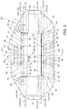
- FIG. 6 is a section taken along an axial and circumferential cutting plane which illustrates a brake caliper
- FIG. 7 is an axonometric view of a section taken along a radial and circumferential cutting plane of a caliper body, which illustrates the wheel side elongated element inner side;
- FIG. 8 is an axonometric view of a section taken along a radial and circumferential cutting plane of a caliper body, which illustrates the opposite wheel side elongated element inner side;
- FIG. 9 shows a radially inner axonometric view of a caliper body, in which an associable pad is shown transparent and mounted on the inner side of the opposite wheel side elongated element;
- FIG. 10 shows a radially inner axonometric view of a brake caliper, in which a pad is shown transparent and mounted on the wheel side elongated element inner side;
- FIG. 11 shows a radially outer axonometric view of a brake caliper, according to an embodiment
- FIG. 12 shows a radially inner axonometric view of a brake caliper, according to an embodiment
- FIG. 13 is a diagrammatic section taken along a longitudinal plane of a brake caliper, according to an embodiment.
- a caliper body 1 for a brake caliper 101 for disc brake 100 is provided.
- the caliper body 1 is adapted to be arranged straddling a brake disc 2 .
- the brake disc 2 comprises a brake disc first braking surface 7 and an opposite brake disc second braking surface 8 .
- the disc brake 100 defines an axial direction X-X, either coinciding with or parallel to the rotation axis of the brake disc 2 , a radial direction R-R, orthogonal to the axial direction X-X, and a circumferential direction C-C, orthogonal to both the axial direction X-X and the radial direction R-R.
- the caliper body 1 comprises a wheel side first elongated element 9 , comprising a first elongated element caliper outer side 10 and a first elongated element caliper inner side 11 , or wheel side elongated element inner side 11 , in which the first elongated element caliper outer side 10 is adapted to face a vehicle wheel and in which the first elongated element caliper inner side 11 is adapted to face the first brake disc braking surface 7 , either directly or indirectly, by means of at least one first pad 14 .
- the caliper body 1 comprises an opposite wheel side second elongated element 3 , comprising a second elongated element caliper outer side 4 and a second elongated element caliper inner side 5 , or opposite wheel side elongated element inner side 5 , wherein the second elongated element caliper inner side 5 is adapted to face, either directly or indirectly, by means of at least one second pad 16 opposite to the second brake disc braking surface 8 .
- a middle plane M-M is defined orthogonal to the axial direction X-X and interposed between the first elongated element caliper inner side 11 and the second elongated element caliper inner side 5 .
- the middle plane M-M is a median working plane which can be defined in the caliper body 1 .
- the middle plane M-M defines an axially outer sense XE-XE directed in axial direction X-X from the middle plane M-M. Consequently, an axially inner sense is defined as the sense opposite to the axially outer sense XE-XE.
- a radially outer sense RE-RE is further defined directed in radial direction R-R by the rotation axis of the brake disc 2 .
- a radially inner sense is defined as the sense opposite to the radially outer sense RE-RE.
- the middle plane M-M as parallel to the brake disc first braking surface 7 and to the brake disc opposite second braking surface 8 , the middle plane M-M may be interposed between the first brake disc braking surface 7 and the brake disc second braking surface 8 .
- the at least one first pad 14 and the at least one second pad 16 comprise a friction material 30 and a support plate 31 comprises a back 29 facing opposite to the friction material 30 .
- the back 29 is made in one piece with the support plate 31 .
- the back 29 is made in a separate piece and then assembled to the support plate 31 .
- At least either the wheel side first elongated element 9 or the opposite wheel side second elongated element 3 comprises at least one thrust means housing 12 adapted to receive thrust means, adapted to bias either the first pad 14 against the brake disc first braking surface 7 or the second opposite pad 16 against the second opposite brake disc braking surface 8 .
- the thrust means housing 12 is the cylinder of a cylindrical piston assembly.
- the at least one thrust means housing 12 is substantially cup-shaped and comprises a housing bottom wall 27 and a housing lead-in portion 28 , axially opposite to the housing bottom wall 27 .
- the at least one housing lead-in portion 28 comprises at least one housing edge surface 33 , adapted to face a back 29 of a support plate 31 of a pad 14 or 16 which can be associated with the caliper body 1 .
- the housing edge surface 33 defines a housing mouth plane LX 1 -LX 1 substantially parallel to the middle plane M-M.
- the caliper body 1 further comprises at least one first caliper bridge 6 , which connects the wheel side first elongated element 9 and the opposite wheel side second elongated element 3 , so as to be adapted to straddle the brake disc 2 .
- first elongated element caliper inner side 11 or the second elongated element caliper inner side 5 comprises at least one groove bottom wall 18 and groove sides 19 which delimit at least one groove 20 or slot 20 .
- groove means a channel which extends along a predetermined longitudinal path which, at least for a portion of its longitudinal path, not entirely surrounded by caliper body walls 1 and is adapted to face directly, by means of a least one longitudinal groove window, the back 29 of the support plate 31 of the at least one pad 14 or 16 which can be associated with the caliper body 1 .
- Providing the at least one groove 20 makes it possible to cool the caliper body 1 , when in working conditions, by forming a thermal barrier between the caliper body 1 and the heat source, which is at least a braking surface of the disc 7 or 8 which is in contact with the friction material 30 of the pad 14 or 16 transfers the heat to the support plate 31 .
- the groove bottom wall 18 is adapted to face the back 29 of the support plate 31 of a pad 14 or 16 which can be associated with the caliper body 1 , by means of at least a longitudinal groove window.
- the groove sides 19 comprise two opposite groove sides 19 .
- the groove bottom wall 18 is made in one piece with the groove sides 19 .
- the groove bottom wall 18 and the groove sides 19 are portions of a single curved surfaces, facing the groove 20 .
- the at least one groove bottom wall 18 is axially outer which respect to the housing edge surface 33 .
- the at least one groove bottom wall 18 is axially outer which respect to the reference plane LX 1 -LX 1 .
- the at least one groove 20 comprises at least one first groove mouth 23 , or radially outer groove mouth 23 , and at least one opposite groove mouth 25 , or radially inner groove mouth 25 , at the opposite end of the longitudinal path of the groove 20 .
- “Longitudinal path” means the longitudinal development of the groove 20 .
- the caliper body 1 is associated with air conveying means, adapted to convey air to the at least one groove 20 .
- the air conveying means comprise at least one air conveying channel.
- the air conveying means comprise a pipe made in one piece or separate piece with respect to the caliper body 1 .
- the first caliper bridge 6 at least partially delimits with an opening edge 24 thereof at least one bridge opening 22 , or wheel opposite side bridge opening 22 , in which the at least bridge opening 22 puts the second elongated element caliper inner side 5 into communication with the second elongated element caliper outer side 4 .
- the first caliper bridge 6 at least partially delimits a cooling air conveying channel 40 , or air conveying channel 40 , which extends longitudinally to the first caliper bridge 6 .
- the cooling air conveying channel 40 is in fluid communication with the bridge opening 22 .
- the air conveying channel 40 prevalently extends in axial direction X-X between the wheel side elongated element inner side 5 and the opposite wheel side elongated element inner side 11 .
- the first groove mouth 23 , or groove radially outer mouth 23 , or channel side mouth 23 , of the at least one groove 20 fluidically connects the at least one groove 20 and the cooling air conveying channel 40 .
- the opening 22 works as collection vent of the air which is forced, by means of the air conveying channel 40 and the at least one channel side mouth 23 , to flow in the at least one groove 20 and to exit from the caliper body 1 through the opposite groove mouth 25 .
- the opposite groove mouth 25 leads outside the caliper body 1 .
- the at least one groove 20 is delimited by the groove bottom wall 18 and by opposite groove sides 19 , thus avoiding the need to provide a covering wall made in one piece with the caliper body 1 along the longitudinal path of the groove 20 .
- groove bottom wall 18 is entirely adapted to face the back 29 of the support plate 31 of a pad 14 or 16 which can be associated with the caliper body 1 , by means of a single groove window which extends along the entire longitudinal path of the groove 20 .
- the first caliper bridge 6 comprises an inner bridge side 41 , adapted to face either directly or indirectly a brake disc 2 which can be associated with the caliper body 1 , wherein the inner bridge side 41 at least partially delimits the air conveying channel 40 .
- the air conveying channel 40 is delimited by a channel bottom wall 39 , either directly or indirectly facing a brake disc 2 which can be associated with the caliper body 1 , and by channel sides.
- the channel extends along a prevalent path in axial direction X-X, wherein at least for a prevalent portion of its path in axial direction X-X, it is not entirely surrounded by walls of the caliper body 1 and faces either directly or indirectly the brake disc 2 which can be associated with the caliper body 1 . Instead, according to a preferred embodiment, no opening is made between the first caliper bridge 6 and the wheel side first elongated element 9 .
- the caliper body 1 comprises at least one partition 42 which delimits at least one prevalent portion of the longitudinal path, e.g. in axial direction X-X, of the air conveying channel 40 , so that the air conveying channel 40 is radially delimited for a prevalent portion thereof.
- the channel bottom wall 39 faces the partition 42 .
- the partition 42 separates the air conveying channel 40 from the brake disc 2 and/or of the pads 14 or 16 , making it possible to thermally insulate the cooling current which flows in the conveying channel 40 from the heat of the brake disc 2 , avoiding the heat of the disc braking surfaces 7 , 8 as well as the pads 14 , 16 to be transmitted to the cooling fluid current, thereby heating it.
- the partition 42 is radially interrupted outside the channel mouth 23 of the at least one groove 20 .
- the partition 42 is radially interrupted outside the radially outer edge 17 of the caliper body 1 .
- the partition 42 is a blade spring, adapted to bias the pads 14 , 16 elastically in axial direction X-X or circumferential direction C-C.
- the caliper body 1 further comprises at least one caliper bridge 13 which connects the wheel side first elongated element 9 and the opposite wheel side second elongated element 3 , so as to be adapted to be arranged straddling the brake disc 2 , wherein the at least one second caliper bridge 13 and the at least one first caliper bridge 6 delimit at least one caliper body opening 44 , adapted to promote the evacuation of heat accumulated in the brake disc 2 .
- the least one second caliper bridge 13 is free from air conveying channels.
- the at least one second caliper bridge 13 is arranged circumferential externally with respect to the at least one first caliper bridge 6 .
- the caliper body 1 comprises at least two second circumferentially outer caliper bridges 13 with respect to the at least one first caliper bridge 6 .
- the opposite wheel side second elongated element 3 comprises a radially inner edge 15 and a radially outer edge 17 , which delimits the dimension in radial direction R-R of the opposite wheel side second elongated element 3 .
- the at least one groove 20 connects at least one portion of the radially inner edge 15 to the radially outer edge 17 , so as to allow a cooling fluid current flow between the bridge opening 22 and the radially inner edge 15 of the opposite wheel side second elongated element 3 .
- the first elongated wheel side 9 comprises a radially inner edge 15 and a radially outer edge 15 .
- the at least one housing lead-in edge portion 28 comprises a body made in one piece with the caliper body 1 .
- the body of the at least one housing lead-in edge portion 28 is associated with at least one connection rib 34 , or connection staple 34 , which connects the body of the at least one housing lead-in edge portion 28 to the caliper body 1 .
- the body of the at least one housing lead-in edge portion 28 protrudes axially projecting from at least either the first elongated element caliper inner side 11 or the second elongated element caliper inner side 5 , thereby forming a cooling surface 21 facing the groove 20 , except for the connection rib 34 .
- connection rib 34 comprises a staple surface 35 , adapted to face the back 29 of the support plate 31 of a pad 14 or 16 which can be associated with the caliper body 1 .
- the staple surface 35 is coplanar with the housing edge surface 33 .
- the staple surface 35 is substantially coplanar with the reference plane LX 1 -LX 1 .
- the housing edge surface 33 seamlessly continues in the staple surface 35 .
- the body of the at least one housing lead-in edge portion 28 comprises at least one cooling surface 21 facing the groove 20 , wherein the at least one cooling surface 21 is free from the material of the caliper body 1 .
- the cooling surface 21 faces opposite to the thrust means housing 12 . In this manner, the cooling surface 21 of the body of the housing lead-in edge portion 28 can be exposed to the cooling air current flow, whereby improving the cooling of the at least one thrust means housing 12 , and consequently of thrust means which can be associated with the at least one thrust means housing.
- the at least one groove 20 extends to surround at least partially the portion of housing lead-in edge 28 .
- the at least one groove bottom wall 18 at least partially surrounds the body of the housing lead-in edge portion 28 . In this manner, a cooling fluid current can flow about the body of the housing lead-in edge portion 28 , whereby cooling it.
- the body of the housing lead-in edge portion 28 is substantially annular about the thrust means housing 12 .
- the at least one cooling surface 21 is substantially annular to surround the body of the housing lead-in edge portion 28 and is interrupted only by at least one connection rib 34 .
- the at least one cooling surface 21 is substantially cylindrical and interrupted by the at least one connection rib 34 . According to an embodiment, the at least one cooling surface 21 is substantially truncated-cone-shaped and interrupted by the at least one connection rib 34 .
- the groove bottom wall 18 is connected to the cooling surface 21 of the housing lead-in edge portion 28 .
- the extraction of the caliper body 1 from the die is facilitated during the manufacturing of the caliper body 1 , e.g. by means of foundry techniques, such as sand casting or shell casting.
- the at least one groove 20 comprises at least two groove branches which join in a radially outer portion with respect to the at least one housing lead-in edge 28 .
- the at least one housing lead-in edge portion 28 comprises at least one portion of at least one groove side 19 .
- the cooling surface 21 of the housing lead-in edge portion 28 at least in one portion thereof coincides with a groove side 19 .
- the at least one housing lead-in edge portion 28 is substantially annular which surrounds the opening of the thrust means housing 12 .
- the at least one housing edge surface 33 is substantially circular crown shaped and surrounds the opening of the thrust means housing 12 .
- the housing lead-in edge portion 28 comprises at least one seal housing slot 32 , adapted to receive a portion of a seal, e.g. a portion of a dust boot for thrust means which can be associated with the thrust means housing 12 .
- the housing edge surface 33 is interrupted by the at least one seal housing slot 32 .
- the seal housing slot 32 is substantially ring-shaped.
- the at least one housing lead-in edge portion 28 comprises at least two housing edge surfaces 33 which are substantially circular-crown-shaped and mutually concentric, separated by at least one seal housing slot 32 .
- the at least one groove 20 has a prevalent extension in radial direction R-R.
- the at least one groove bottom wall 18 prevalently extends in radial direction R-R.
- the at least one groove bottom wall 18 defines a groove bottom plane LX 2 -LX 2 , substantially parallel to the middle plane M-M and axially outer with respect to the reference plane LX 1 -LX 1 .
- At least either the first elongated element caliper inner side 11 and the second elongated element caliper inner side 5 comprise at least one inner side surface 26 , adapted to face directly the back 29 of the support plate 31 of a pad 14 or 16 which can be associated with the caliper body 1 , wherein the at least one inner side surface 26 is axially outside the housing edge surface 33 and axially inside the groove bottom wall 18 .
- a multilevel caliper inner side surface axially external to the housing edge surface 33 can be made, adapted to convey the cooling fluid current about the cooling surface of the body of the housing lead-in edge portion 28 .
- the at least one inner side surface 26 defines an inner side plane LX 3 -LX 3 , substantially parallel to the middle plane M-M.
- the inner side plane LX 3 -LX 3 is axially outside the reference plane LX 1 -LX 1 and is axially inside the groove bottom plane LX 2 -LX 2 .
- the inner side plane LX 3 -LX 3 is axially interposed between the reference plane LX 1 -LX 1 and the groove bottom plane LX 2 -LX 2 .
- At least either the first elongated element caliper inner side 11 or the second elongated element caliper inner side 5 comprises surfaces arranged on at least three levels, whereby promoting the circulation of a fluid cooling current between the caliper body 1 and the back 29 of the support plate 31 of a pad 14 or 16 and at the same time providing a satisfactory structural resistance to the stresses arising during the braking action to the caliper body 1 .
- the at least one portion of housing lead-in edge 28 protrudes axially projecting either from the inner side surface 26 or from the groove surface 18 , except for the connection staple 34 .
- At least either the inner side surface 26 and the groove bottom surface 18 extends to surround the housing lead-in edge portion 28 , except for the connection staple 34 .
- the inner side surface 26 and the groove bottom surface 20 surround the housing lead-in edge portion 28 , except for the connection staple 34 . In this manner, a cooling fluid current can flow about the housing lead-in edge portion 28 , thereby cooling it.
- the at least one groove 20 interrupts the inner side surface 26 .
- the inner side surface 26 is joined to the groove bottom wall 18 and with the cooling surface 21 of the housing lead-in edge portion 28 .
- the at least one radially inner groove mouth 25 which leads into the radially inner edge 15 increases by extension in circumferential direction C-C approaching the radially inner edge 15 .
- the opposite groove sides 19 of the radially inner mouth 25 are mutually distanced in circumferential direction C-C, whereby increasing the cross section of the groove 20 .
- the at least one radially inner groove mouth 25 increases by extension in axial direction X-X, approaching the radially inner edge 15 .
- the groove bottom wall 18 moves away from the facing back 29 of a support plate 31 of a pad 14 or 16 which can be associated with the caliper body 1 , whereby increasing the cross section of the groove 20 .
- At least either the wheel side first elongated element 9 or the opposite wheel side second elongated element 11 comprise at least two circumferentially facing housing lead-in mouth portions 28 , which each delimit a thrust means housing 12 , wherein the at least one groove 20 extends between the at least two housing lead-in edge portions 28 forming a groove bottleneck 38 of minimum circumferential extension.
- the walls of two circumferentially facing housing lead-in edge portions 28 delimit a groove bottleneck 38 , having small circumferential extension.
- the groove bottom wall 18 interposed between two circumferentially facing housing lead-in edge portions 28 has minimum circumferential extension.
- the at least one groove 20 is substantially Venturi-tube-shaped.
- At least either the wheel side first elongated element 9 or the opposite wheel side second elongated element 3 comprises at least three housing lead-in edge portions 28 arranged circumferentially side-by-side, which each delimit a thrust means housing 12 , wherein at least one groove 20 is interposed between two housing lead-in edge portions 28 arranged side-by-side and successive, and wherein an inner side surface 26 forms an island which at least partially surrounds the housing lead-in edge portion 28 interposed between two housing lead-in edge portions which are arranged circumferentially side-by-side 28 .
- At least either the first elongated element caliper inner side 11 or the second elongated element caliper inner side 5 comprises circumferentially facing opposite shoulder walls 36 , adapted to form opposite circumferential abutment references for the support plate 31 of the first pad 14 or the second pad 16 , respectively, and which at least partially delimit a housing pocket 37 , adapted to receive at least one portion of the first pad 14 or of the second pad 16 , respectively.
- the at least one connection staple 34 connects the housing lead-in edge portion 28 to one of the shoulder walls 36 .
- the caliper body 1 further comprises a brake fluid feeding pipe 43 , in fluid communication with at least one thrust means housing 12 .
- At brake caliper 101 comprises a caliper body 1 according to any of the embodiments described above, and at least one pad 14 , 16 .
- the at least one groove bottom wall 18 of the caliper body 1 faces the back 29 of the support plate 31 of the at least one pad 14 or 16 of the brake caliper 101 .
- the brake caliper 101 comprises thrust means accommodated in respective thrust means housings 12 .
- the thrust means comprise at least one piston.
- a disc brake 100 comprises at least one brake caliper 101 according to any one of the embodiments described above, and at least one brake disc 2 having opposite braking surfaces 7 , 8 .
- a caliper body 1 a brake caliper 101 and a disc brake 100 can be obtained, which at the same time satisfy the aforesaid mutually contrasting needs and achieve the aforesaid desired advantages, and in particular:
Abstract
Description
-
- allow the efficient cooling of the
caliper body 1; - allow the formation of a thermal barrier between the
caliper body 1 and the heat source also during the braking action; - keep the brake fluid temperature sufficiently low to prevent it from boiling, guaranteeing prompt braking;
- make it possible to obtain a
caliper body 1 which is resistant to the stress arising from the braking action.
- allow the efficient cooling of the
- 45. caliper body
- 46. brake disc
- 47. second elongated element opposite wheel side
- 48. second elongated element caliper outer side
- 49. second elongated element caliper inner side, or opposite wheel side elongated element inner side
- 50. central caliper bridge
- 51. disc braking surface
- 52. opposite disc braking surface
- 53. first elongated element wheel side
- 54. first elongated element caliper outer side
- 55. first elongated element caliper inner side, or wheel side elongated element inner side
- 56. thrust means housing
- 57. side caliper bridge
- 58. first pad
- 59. radially inner edge
- 60. second pad
- 61. radially outer edge
- 62. groove bottom wall
- 63. groove side
- 64. groove, or slot
- 65. cooling surface of the housing lead-in edge portion
- 66. bridge opening
- 67. mouth side channel, or first groove mouth, or radially outer groove mouth
- 68. central caliper bridge opening edge
- 69. opposite groove mouth, or second groove mouth, or radially inner groove mouth
- 70. inner side surface
- 71. housing bottom wall of the thrust means housing
- 72. housing lead-in edge portion of the thrust means housing
- 73. support plate back
- 74. friction material
- 75. support plate
- 76. housing seal groove
- 77. housing bottom surface
- 78. connection staple, or connection rib
- 79. staple surface
- 80. shoulder wall
- 81. housing pocket
- 82. groove bottleneck
- 83. channel bottom wall
- 84. air conveying channel
- 85. bridge inner side of central caliper bridge
- 86. partition
- 87. brake fluid feeding pipe
- 88. brake caliper opening
- X-X. axial direction
- XE-XE. axially outer sense
- R-R. radial direction
- RE-RE. radially outer sense
- C-C. circumferential or tangential direction
- M-M. middle plane
- LX1-LX1. reference plane
- LX2-LX2. groove bottom plane
- LX3-LX3. inner side plane
Claims (10)
Applications Claiming Priority (3)
| Application Number | Priority Date | Filing Date | Title |
|---|---|---|---|
| IT102016000130165 | 2016-12-22 | ||
| IT102016000130165A IT201600130165A1 (en) | 2016-12-22 | 2016-12-22 | Caliper body for disc brake, brake caliper and disc brake |
| PCT/IB2017/057940 WO2018127751A1 (en) | 2016-12-22 | 2017-12-14 | Caliper body for disc brake, brake caliper and disc brake |
Publications (2)
| Publication Number | Publication Date |
|---|---|
| US20190323569A1 US20190323569A1 (en) | 2019-10-24 |
| US11149809B2 true US11149809B2 (en) | 2021-10-19 |
Family
ID=58609858
Family Applications (1)
| Application Number | Title | Priority Date | Filing Date |
|---|---|---|---|
| US16/472,565 Active 2038-01-09 US11149809B2 (en) | 2016-12-22 | 2017-12-14 | Caliper body for disc brake, brake caliper and disc brake |
Country Status (5)
| Country | Link |
|---|---|
| US (1) | US11149809B2 (en) |
| EP (1) | EP3559496B1 (en) |
| CN (1) | CN110199138B (en) |
| IT (1) | IT201600130165A1 (en) |
| WO (1) | WO2018127751A1 (en) |
Families Citing this family (3)
| Publication number | Priority date | Publication date | Assignee | Title |
|---|---|---|---|---|
| US10539199B2 (en) | 2017-01-20 | 2020-01-21 | Akebono Brake Industry Co., Ltd | Multi-piston caliper |
| CN111795088A (en) * | 2020-05-25 | 2020-10-20 | 深圳市车质汇汽车配件有限公司 | Automobile brake caliper and manufacturing method thereof |
| KR20220170177A (en) | 2021-06-22 | 2022-12-29 | 에이치엘만도 주식회사 | Disk Brake |
Citations (9)
| Publication number | Priority date | Publication date | Assignee | Title |
|---|---|---|---|---|
| EP1016804A1 (en) | 1998-12-31 | 2000-07-05 | Freni Brembo S.p.A. | Cooling device for motor vehicle disk brake |
| US20080277216A1 (en) | 2004-09-29 | 2008-11-13 | Freni Brembo S.P.A. | Disc Brake Caliper with a Cooling Duct |
| WO2010051135A1 (en) | 2008-10-29 | 2010-05-06 | Finkel Brian G | Brake caliper including heat pipes |
| EP2284415A1 (en) | 2006-12-18 | 2011-02-16 | Freni Brembo S.p.A. | Brake caliper with cooling system |
| US20110048870A1 (en) * | 2007-06-05 | 2011-03-03 | Ferrari S.P.A. | Disc brake caliper with cooling pipes |
| US20150027822A1 (en) | 2011-09-20 | 2015-01-29 | Freni Brembo S.P.A. | Calliper Body for Disc Brake |
| US20160327107A1 (en) * | 2013-12-30 | 2016-11-10 | Freni Brembo S.P.A. | Disc brake caliper body |
| US20160369858A1 (en) * | 2014-02-14 | 2016-12-22 | Newbridge Brake Ltd | Disc brake caliper |
| US20180216681A1 (en) * | 2015-07-30 | 2018-08-02 | Jaguar Land Rover Limited | Brake caliper |
Family Cites Families (2)
| Publication number | Priority date | Publication date | Assignee | Title |
|---|---|---|---|---|
| US20060289249A1 (en) * | 2005-06-22 | 2006-12-28 | Seiji Nishimura | Sliding cylinder bore caliper assembly |
| IT1399203B1 (en) * | 2010-03-31 | 2013-04-11 | Freni Brembo Spa | BODY CALIPER OF A DISC BRAKE |
-
2016
- 2016-12-22 IT IT102016000130165A patent/IT201600130165A1/en unknown
-
2017
- 2017-12-14 US US16/472,565 patent/US11149809B2/en active Active
- 2017-12-14 EP EP17829292.6A patent/EP3559496B1/en active Active
- 2017-12-14 WO PCT/IB2017/057940 patent/WO2018127751A1/en unknown
- 2017-12-14 CN CN201780083701.8A patent/CN110199138B/en active Active
Patent Citations (9)
| Publication number | Priority date | Publication date | Assignee | Title |
|---|---|---|---|---|
| EP1016804A1 (en) | 1998-12-31 | 2000-07-05 | Freni Brembo S.p.A. | Cooling device for motor vehicle disk brake |
| US20080277216A1 (en) | 2004-09-29 | 2008-11-13 | Freni Brembo S.P.A. | Disc Brake Caliper with a Cooling Duct |
| EP2284415A1 (en) | 2006-12-18 | 2011-02-16 | Freni Brembo S.p.A. | Brake caliper with cooling system |
| US20110048870A1 (en) * | 2007-06-05 | 2011-03-03 | Ferrari S.P.A. | Disc brake caliper with cooling pipes |
| WO2010051135A1 (en) | 2008-10-29 | 2010-05-06 | Finkel Brian G | Brake caliper including heat pipes |
| US20150027822A1 (en) | 2011-09-20 | 2015-01-29 | Freni Brembo S.P.A. | Calliper Body for Disc Brake |
| US20160327107A1 (en) * | 2013-12-30 | 2016-11-10 | Freni Brembo S.P.A. | Disc brake caliper body |
| US20160369858A1 (en) * | 2014-02-14 | 2016-12-22 | Newbridge Brake Ltd | Disc brake caliper |
| US20180216681A1 (en) * | 2015-07-30 | 2018-08-02 | Jaguar Land Rover Limited | Brake caliper |
Non-Patent Citations (1)
| Title |
|---|
| European Patent Office, International Search Report and Written Opinion in Application No. PCT/IB2017/057940, dated May 2, 2018, 12 pages, Rijswijk, Netherlands. |
Also Published As
| Publication number | Publication date |
|---|---|
| CN110199138A (en) | 2019-09-03 |
| IT201600130165A1 (en) | 2018-06-22 |
| US20190323569A1 (en) | 2019-10-24 |
| EP3559496A1 (en) | 2019-10-30 |
| WO2018127751A1 (en) | 2018-07-12 |
| CN110199138B (en) | 2020-10-30 |
| EP3559496B1 (en) | 2020-08-19 |
Similar Documents
| Publication | Publication Date | Title |
|---|---|---|
| US11149809B2 (en) | Caliper body for disc brake, brake caliper and disc brake | |
| EP2976542B1 (en) | Disc brake caliper with reduced axial dimension | |
| US4641731A (en) | Disc brake for motorcycles | |
| US10520053B2 (en) | Heat shield element | |
| GB2143903A (en) | Hydraulically-actuated wheel brake | |
| EP1392986B1 (en) | Brake piston | |
| US10738850B2 (en) | Disc brake calliper body | |
| US3483953A (en) | Disc element construction for disc brake | |
| JP2018096402A (en) | Caliper for opposite piston type disc brake | |
| CN115551780A (en) | Heat shield for aircraft wheel brake | |
| EP3717317B1 (en) | Brake caliper thrust device, brake caliper and manufacturing method | |
| US5127494A (en) | Disk brake with a thermally insulated working chamber | |
| CN113272570B (en) | Caliper body, disc brake caliper and disc brake | |
| EP3807551B1 (en) | Disc assembly of disc brake | |
| KR101994113B1 (en) | Vented Brake Disc | |
| CN109312795B (en) | Caliper body for a caliper of a disc brake | |
| CN106989123B (en) | Double-connection disc type brake rotor | |
| US20180180112A1 (en) | Friction surface | |
| EP3899310B1 (en) | Disc assembly of disc brake | |
| US20230313856A1 (en) | Caliper body for brake caliper, brake caliper, and disc brake | |
| JP2006029489A (en) | Disc brake provided with hydraulically operated piston | |
| JP2018141534A (en) | Disc brake device |
Legal Events
| Date | Code | Title | Description |
|---|---|---|---|
| FEPP | Fee payment procedure |
Free format text: ENTITY STATUS SET TO UNDISCOUNTED (ORIGINAL EVENT CODE: BIG.); ENTITY STATUS OF PATENT OWNER: LARGE ENTITY |
|
| AS | Assignment |
Owner name: FRENI BREMBO S.P.A., ITALY Free format text: ASSIGNMENT OF ASSIGNORS INTEREST;ASSIGNORS:CRIPPA, CRISTIAN;D'ALESSIO, DAVIDE;REEL/FRAME:050390/0158 Effective date: 20190823 |
|
| STPP | Information on status: patent application and granting procedure in general |
Free format text: DOCKETED NEW CASE - READY FOR EXAMINATION |
|
| STPP | Information on status: patent application and granting procedure in general |
Free format text: RESPONSE TO NON-FINAL OFFICE ACTION ENTERED AND FORWARDED TO EXAMINER |
|
| STPP | Information on status: patent application and granting procedure in general |
Free format text: FINAL REJECTION MAILED |
|
| STPP | Information on status: patent application and granting procedure in general |
Free format text: RESPONSE AFTER FINAL ACTION FORWARDED TO EXAMINER |
|
| STPP | Information on status: patent application and granting procedure in general |
Free format text: NOTICE OF ALLOWANCE MAILED -- APPLICATION RECEIVED IN OFFICE OF PUBLICATIONS |
|
| STPP | Information on status: patent application and granting procedure in general |
Free format text: PUBLICATIONS -- ISSUE FEE PAYMENT VERIFIED |
|
| STCF | Information on status: patent grant |
Free format text: PATENTED CASE |
|
| AS | Assignment |
Owner name: BREMBO S.P.A., ITALY Free format text: CHANGE OF NAME;ASSIGNOR:FRENI BREMBO S.P.A.;REEL/FRAME:061959/0605 Effective date: 20210429 |